Vocia® WS4/WS10 & EWS4/EWS10 Operation Manual Biamp Systems, 9300 S.W. Gemini Drive, Beaverton, Oregon 97008 U.S.A. (503) 6417287 www.biamp.
IMPORTANT SAFETY INSTRUCTIONS 1) Read these instructions. 10) Protect the power cord from being walked on or pinched particularly at plugs, convenience receptacles, and the point where they exit from the apparatus. 2) Keep these instructions. 3) Heed all warnings. 4) Follow all instructions. 11) Only use attachments/accessories specified by the manufacturer. WARNING - To reduce the risk of fire or electric shock, do not expose this apparatus to rain or moisture.
TABLE OF CONTENTS VOCIA WALL STATION 4/10 (WS4/WS10) & VOCIA EMERGENCY WALL STATION 4/10 (EWS4/EWS10) FEATURES . . . . . . . . . . . . . . . . . . . . . . . 4 FRONT VIEW . . . . . . . . . . . . . . . . . . . . . . . . . . . . . . . . . . . . . . . . . . . . . . . . . . . . . . . . . . . . . . . . . . . . . . . . . . . . . . . . . . . . . . 5 Setup and Use . . . . . . . . . . . . . . . . . . . . . . . . . . . . . . . . . . . . . . . . . . . . . . . . . . . . . . . . . . . . . . . . . . . . . . . . . . .
VOCIA WALL STATION 4/10 (WS4/WS10) & VOCIA EMERGENCY WALL STATION 4/10 (EWS4/EWS10) FEATURES WS4 WS10 EWS4 EWS10 The WS4 and WS10 (including the EWS4 and EWS10) are wallmounted networked paging stations for use in Vocia® systems. Both the !"#$%&'(%!"#)*%+,&-./,%,01,((,(%2"3%&'(%4'#14&/(%0,04/5%-4%6.774/-%6-&'(&/(%&'(%&(8&'9,(%7.1:;9%&((/,66%&'(%0&66%'4-;<9&-;4'% +.'9-;4'&:;-;,6=%>?,%!"#$%9&'%6-4/,%+4./%.6,/#94'<@./&1:,%3&@,%A4(,6B%&'(%-?,%!"#)*%9&'%6-4/,%CCC%.6,/#94'<@.
WS4/WS10 & EWS4/EWS10 FRONT VIEW Setup and Use >?,%H49;&%64+-F&/,%7/48;(,6%&'%;'-.;-;8,%;'-,/+&9,%+4/%94'<@./&-;4'E%2"3%,I.&:;G&-;4'%&'(%7/4@/&00;'@%4+%-?,%!"#$%&'(%!"#)*%94074','-6=%>?,% information supplied by this manual relates to physical connections and assignment. For more details on software setup, please consult the Vocia Help File. NOTE: H49;&%64+-F&/,%9&'%94'<@./,%-?,%!"#$%4/%!"#)*%+4/%(,(;9&-,(%.6,%&6%&'%N0,/@,'95%3&@;'@%"-&-;4'=%!?,'% 64%94'<@.
WS4/WS10 & EWS4/EWS10 BACK VIEW Device ID The rotary ID switches are located on the back of the WS4 and WS10 (under the mounting plate) and give the unit a unique Device ID. The switches are in hexadecimal format. All wall station units must have a unique Device ID to function within a Vocia Paging World (i.e., it is not possible to have two wall station units with the same Device ID of hex 07). To assign a Device ID of hex 07, turn the LSB switch to 7 and leave the MSB switch on 0.
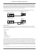
WS4/WS10 & EWS4/EWS10 BACK VIEW >?;6%94'',9-;4'%9&//;,6%94'-/4:%(&-&E%74F,/%&'(%(;@;-&:%&.(;4%48,/%A41/&R,-=%34N#,'&1:,(%',-F4/T%6F;-9?,6%4/%34N%0;(67&'%&(&7-,/6% must be used to power the WS4 or WS10 (including the EWS4 or EWS10. These must be 802.3af compliant and must be isolated with respect to ground. The maximum distance between any unit and an Ethernet switch is 328 feet (100 meters) when using copper cabling. D((;-;4'&:%N-?,/',-%6F;-9?,6%&'(M4/%<1,/#47-;9%9&1:,%9&'%1,%.6,(%-4%+.
WS4/WS10 & EWS4/EWS10 BACK VIEW !"#$%&'()*+"&,-./',-%&)0123"#)4!*05)6"/1#-,7 S4-?%-?,%!"#$%&'(%!"#)*%9&'%1,%94'<@./,(%+4/%3VR%6,9./;-5%7/4-,9-;4'=%",,%-?,%6,9-;4'6%1,:4F%+4/%(;/,9-;4'6%1&6,(%4'%&%67,9;<9%04(,:=% WS4:%V+%3VR%6,9./;-5%;6%,'&1:,(%8;&%-?,%H49;&%64+-F&/,E%-?,%+4./%3&@,%A4(,%1.--4'6%0&5%1,%.6,(%-4%,'-,/%-?,%/,I.;/,(%+4./#(;@;-%3VR%L6,,% 1.--4'%:&1,:;'@%,^&07:,6%1,:4FO=%>4%,'-,/%&%'.01,/E%-?,%.6,/%0&5%',,(%-4%7/,66%&%1.--4'%0.:-;7:,%-;0,6%L&6%;'%"["%0,66&@;'@O=%2.
WS4/WS10 & EWS4/EWS10 DISPLAY Display Status Messages The following messages are used to display the state of the WS4 or WS10 during normal operation. More information on display status messages can be found in the Vocia Help File. 1. Destination Idleb%>?;6%6-&-.6%0,66&@,%;'(;9&-,6%-?&-%-?,%7&@;'@%6-&-;4'%;6%/,&(5%&'(%-?,/,%&/,%'4%1.65%G4',6%&04'@%-?,%(,6-;'&-;4'6% 6,:,9-,(%15%-?,%3&@,%A4(,=% 2.
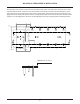
11.555 293.50 241.50 0 83.50 135.50 WS4/WS10 & EWS4/EWS10 INSTALLATION 0.579 14.71 R2 TYPICAL 0 58 83.50 D'5%9401;'&-;4'%4+%-?,%69/,F%?4:,6%6?4F'%;'%-?,%/,&/#8;,F%(;&@/&0%9&'%1,%.6,(%-4%04.'-%-?,%1/&9T,-%-4%-?,%F&::%L(4%'4-%<-%&%69/,F% 5 -4%-?,%?4:,%0&/T,(%R4%"9/,FO=%D%0;';0.0%4+%+4./%69/,F6%6?4.:(%1,%.6,(=%3:,&6,%'4-,b%-?,%0&^;0.0%69/,F%?,&(%?,;@?-%;6%*=)Yc%;'9?% 0 (4mm) (dimension from top of installed screw head to inside of mounting bracket). Screws with larger heads may damage the unit.
WS4/WS10 & EWS4/EWS10 SPECIFICATIONS <'(()6,',-%&)>?@A)E);2"#F"&/7)<'(()6,',-%&)>?@A)6!;G*C*GDH*B06 Frequency Response (electronics): +0,-1dB, 100Hz to 20kHz Effective Input Headroom: 30dB Gain: Adjustable in 1dB steps over a 30dB range System Headroom: 18dB Maximum Input: 125dB SPL THD + N (100Hz to 8kHz): <0.
WS4/WS10 & EWS4/EWS10 MICROPHONE REPLACEMENT 1. Remove microphone from catch. Remove top and bottom screws +/40%-?,%0&;'%14(5%4+%-?,%F&::%6-&-;4'%F;-?%-4/^%69/,F(/;8,/%6;G,%)*%L>)*O=% `=%3.::%1,G,:%-4F&/(6%54.%&'(%1,'(%(4F'%&6%6?4F'%1,:4F=% 3. Detach the white microphone connector from the board (and the Ethernet cable if connected). 4. Use a pointed tool to release the catch located to the right of the microphone on the bottom side of the wall station.
WS4/WS10 & EWS4/EWS10 MICROPHONE REPLACEMENT c=%A4'',9-%-?,%F?;-,%0;9/47?4',%94'',9-4/%&6%6?4F'%1,:4F=% d=%3:&9,%-?,%+/4'-%1,G,:%48,/%-?,%F&::%6-&-;4'%&'(%&--&9?%-?,%-47%&'(%14--40%69/,F6=% 13
WS4/WS10 & EWS4/EWS10 WARRANTY SVD[3%"f">N["%V"%3QND"N2%>U%Ng>NR2%>hN%KUQQU!VR\%Y#fNDX%QV[V>N2%!DXXDR>f%>U%>hN%UXV\VRDQ%3PXAhD"NX%UK% >hN%3XUKN""VURDQ%"UPR2%NiPV3[NR>%2N"AXVSN2%VR%>hV"%[DRPDQ 1. BIAMP Systems warrants to the original purchaser of new products that the product will be free from defects in material and F4/T0&'6?;7% +4/% &% 7,/;4(% 4+% Y% fNDX"% +/40% -?,% (&-,% 4+% 7./9?&6,% +/40% &'% &.-?4/;G,(% SVD[3% "56-,06% (,&:,/E% 6.1j,9-% -4% -?,% terms and conditions set forth below.
COMPLIANCE ! DoC VWS201011! ! ! EC Declaration of Conformity Biamp Systems Corporation, as manufacturer having sole responsibility, hereby declares that the following described product complies with the applicable provisions of the DIRECTIVES below except as noted herein. Any alterations to the product not agreed upon and directed by Biamp Systems Corporation will invalidate this declaration.
COMPLIANCE EU RoHS COMPLIANT! This Biamp product, including all attendant cables and accessories supplied by Biamp, meets all requirements of EU Directives 2002/95/EC of January 27, 2003, and 2005/618/EC of August 18, 2005, the EU RoHS Directives. An EU RoHS Materials Content Declaration document may be obtained at www.biamp.