
How to Guide


AT THE SPEAKER END
1
. Cut off excess wire, leaving about 2 feet
extending through the speaker cut-out hole.
2. Pull the conductors apart so they’re separated
for the first two inches from their ends.
3. Using wire strippers, diagonal pliers or a
knife, remove
1
/
2
inch of insulation from
each conductor.
4. Twist the tiny strands in each conductor into
t
ight spirals, as shown in Drawing 7.
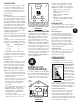
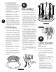
5. IMPORTANT: Route the speaker wire
THROUGH the hole in the ceiling (Drawing 8).
6. Attach the speaker wires to the red and black
speaker terminals. Press down on the
protruding levers while inserting the wire
into the hole (Drawing 8).
s Connect the POSITIVE (+) conductor to
the RED terminal and the NEGATIVE (-)
conductor to the BLACK speaker terminal.
s Make sure that no stray strands of wire
have gotten detached and are touching the
other main wire.
AT THE AMPLIFIER END
1. Cut off excess wire, leaving enough to com-
fortably reach from the hole in the wall to
your stereo system. If there’s a possibility that
you’re going to move the amplifier to ano-
ther part of the room, consider leaving some
excess wire coiled up. If you’ve used suffi-
ciently thick wire, this extra length will not
affect speaker performance and could make
things easier if the room is rearranged later.
2. Pull the conductors on speaker wire(s) apart
so they’re separated for the first two inches.
3. Using wire strippers, diagonal pliers or a
knife, remove
1
/
2
inch of insulation from
each conductor.
4. Twist the tiny strands in each conductor
into tight spirals.
5. Attach the speaker wire(s) to the red and
black speaker terminals on the amplifier
or receiver.
s Connect the POSITIVE (+) conductor to
the RED terminal and the NEGATIVE (-)
conductor to the BLACK speaker terminal.
s Make sure that no stray strands of wire
have gotten detached and are touching the
other main wire.
DRAWING 8
6
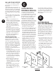
DRAWING 9
FINAL ASSEMBLY
1. If you haven’t done so already during paint-
ing, remove the perforated grilles from
y
our B
.
I
.
C
Ceiling Speaker. To remove
the grille, just use the mounting screw
(dog leg) on the rear to push the grille off.
2. See Drawing 9. Make sure all the clamping
brackets (dog legs) are turned inward as
shown in the picture before going up on the
ladder to install the unit in the ceiling.
3. Find the wire you ran previously (hopefully
hanging down through the hole you cut).
Strip the ends if you haven’t already done so
and connect as described in Section F.
4. Insert the speaker into the cutout hole and
be certain the wire is not hanging down
on the woofer cone.
5. Using a Phillips screwdriver (or powered
screwdriver, recommended), start tightening
the six screws. As you start the tightening
each of the mounting brackets (dog legs) will
swing around and follow the screw down to
the back of the wall and clamp the speaker
into place. Avoid excessive force when
tightening the screws to prevent deforming
the drywall or breaking the plastic clamp of
the speaker. Be sure to go around all six
screws and check for even tightness in the
clamping pressure.
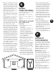
6. Now is the time to aim the midrange unit
and tweeter (if needed) toward your
primary listening area. Gently push on the
rims so the centers are aiming toward the
area you want (See Drawing 10).
7. Replace the grille by gently pressing it into
place. Use the supplied black grille adhesive
around the edge of the grille when pressing
it into place.
G
A SHORT TEST DRIVE
At this point, it’s a good idea to test every-
thing out.
Home Theater System
If you have connected your new B
.
I
.
CCeiling
Speakers to the rear “surround” output of your
receiver, you will need to put your receiver in
the “Pro-Logic” or “Digital” mode and use a
source such as a DVD player or Hi-Fi VCR and
suitably recorded movie to test your receiver
surround operation.
Stereo Music System
1. Turn on your stereo system. Make sure that
the VOLUME control is turned down and that
the BALANCE control is set to center.
2. Activate a musical source such as FM, a tape,
or CD player.
3. Gently turn up the volume. You should hear
music coming out of your new B
.
I
.
C
Ceiling Speakers! (If you don’t, refer to the
troubleshooting guide on the next page.
We suggest you read the section on the next
page titled “Taking care of your new
B
.
I
.
CSpeakers”(for further operating tips).
H
DRAWING 10