
How to Guide


4
WALL AND CEILING SUR-
FACES
Now that we’ve covered where you should
put your speakers, let’s consider where you
CAN put them.
B
.
I
.
C Muro MSR5D’s require at least 2
3
/
4
˝ of
depth, MSR6D’s require at least 3
1
/
16
˝, and
MSR8D’s require at least 3
7
/
16
˝ (measured from
the outside surface of the wall).
This means that they can be installed in any
wallboard-and-2 x 4 stud wall. In fact, the dense,
rigid nature of plasterboard or (lath and plaster
in older homes) acts as a superb speaker baffle.
You can also install B
.
I
.
C Muro speakers in
stud walls covered with thick wood paneling or
in wallboard/plaster ceilings.
However, avoid:
• Stud walls covered only with thin veneer
paneling – the surface isn’t rigid enough and
can cause annoying vibrations and buzzing.
• T-bar “drop ceilings” with very thin
fiberboard panels which can buzz and
vibrate. If you suspect this will happen,
reinforce the drop-in panel with wood or
particle board.
• Any wall which can’t provide proper depth
(clearance) for the back of the Muro
speakers to protrude. This includes brick
or concrete walls where the wallboard or
paneling is attached to thin furring strips.
• Walls where you know that there are pipes,
heating ducts and ESPECIALLY AC wiring in
the general vicinity. For example, if there is
an outlet along the baseboard, there is often
a live wire running partly up the wall at
that point.
SPEAKER WIRE PATHS
The last consideration is the obstacle course
that lies between the speakers’ hoped-for
mounting positions and your stereo system.
Wire can be run through crawl spaces that lie
above your ceiling or below the floor, through
basements of second stories, or simply along
the perimeter of your listening room. We cover
each of these options in detail in the “Running
connecting wires” section of this manual.
In general, you should pay particular attention
to the following areas:
• Avoid running speaker wires close to house
electrical wiring for any distance. If you have
to run them parallel, make sure to space the
speaker wires at least two feet from the AC
line. It is, however, OK for speaker wires to
cross paths with AC line or go through the
same hole together with house wiring if they
separate before and after
.
• Make sure that the entire path between
speakers and amplifier is clear and not
obstructed by a major floor or ceiling joist
or masonry wall which you won’t be able
to drill through.
PAINTING YOUR
SPEAKERS
If you like the designer white finish which
has been applied to your B
.
I
.
C Muro Speakers,
you can skip to Step D, next page. But if you
want your speakers to completely blend in
with a colored wall or accent the surface,
now is the time to paint your Muro speakers’
outer frames and perforated grilles.
The speaker’s outer surfaces are primed to
accept ordinary latex wall paint or aerosol spray
paint. Because the surface behind the perforat-
ed grille should remain black, you will need to
mask this area off before you begin painting.
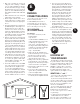
1. First the speakers’ grille must be removed.
From the back of the speaker, use the
mounting legs to push the grille off.
2. Paint the outer speaker frame and grille
separately. A roller with a short or medium
nap will work much better than a brush. If
you’re using spray paint, make sure that
you achieve the same coverage on both
grille and frame. You must take extreme
precautions when painting the grille not to
get paint in the holes of the grille.
There’s no need to replace the grille at this
time since you will need access to the inner
speaker surface during installation.
C
• Remember that the other end of the wires
has to come out somewhere to connect
with the amplifier. Confirm ahead of time
that you can drill an outlet hole easily and
in an unobtrusive spot.
D
CUTTING HOLES
FOR THE SPEAKERS
Wallboard is an easy surface in which
to make a relatively neat hole. Actually, the
hole doesn’t even have to be that neat, since
the speaker’s outer frame will cover it. Just
make sure you don’t make it any bigger than
the template. In the following steps, you’re
going to locate a section of ceiling between
the woodframing or in the wall between two
studs, mark the outer boundaries of the hole,
drill a small hole in the center to confirm
your location and then cut the main hole.
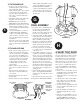
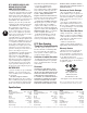
DRAWING 5
A. Trace template
outline
B. Drill 1 inch
pilot hole
C. Probe with
wire for stud
clearance
D. Cut speaker
hole along outline
1. First you must determine the location of your
ceiling supports or wall studs so that the
speaker can be approximately centered
between them. There are several ways to go
about this:
• Tap on the surface and listen to the result-
ing “THUMP”. When it’s deeper, you’re
between studs. When it’s sharper and more
flat-sounding, you’re close to a stud.
• Use a stud-finder, a simple little magnetic
device which works by locating the lines of
nails hammered into the stud.
• Identify wall studs by the position of elec-
trical outlets or switches. There’ll be a stud
either directly to the left or right of an elec-
trical fixture. This gives you a point of mea-
surement, since studs are either 18 or 16
inches apart in newer houses, 12 inches
apart on pre-WW2 homes.