IUPS-401 400VA Benutzerhandbuch / User’s Manual | IUPS-401 Deutsch English
Deutsch Benutzerhandbuch IUPS-401-Serie IUPS-401 mit Standard-Frontblende IUPS-401 mit gewechselter, schwarzer Frontblende IUPS-401-Serie Integrierte USV 2
Benutzerhandbuch IUPS-401-Serie Allgemein...................................................................................... 4 1.1 Lieferumfang und Lagerung....................................................... 4 1.2 Systembeschreibung IUPS........................................................... 4 1.3 Automatische EIN/AUS-Funktion............................................. 4 1.4 Überlastschutz...................................................................................... 5 1.
Benutzerhandbuch IUPS-401-Serie 1. Allgemein 1.1 Lieferumfang und Lagerung Überprüfen Sie sofort nach Erhalt Ihrer IUPS ob Lieferschäden vorliegen. Eine beschädigte Verpackung kann ein Anzeichen hierfür sein. Im Lieferumfang enthalten sind: 1 USV-Gerät IUPS |1 Netzkabel | 1 schwarze Frontplatte | 1 Benutzerhandbuch Deutsch Bei IUPS-401/-B5/-BB/-BC: 1 Slotblech mit USB-Platine 1 internes USB-Kabel 1 externes USB-Kabel 2.
Benutzerhandbuch IUPS-401-Serie 1.4 Überlastschutz Der Laststrom wird von der IUPS überwacht. Bei Überlast während des Batteriebetriebs schaltet die IUPS ab. Bei Überlastung im Netzbetrieb ist ein Dauerton zu hören, der bei Beseitigung der Überlast erlischt. 1.5 Übertemperaturschutz Die interne Temperaturüberwachung signalisiert eine auftretende Übertemperatur durch die rote LED und eine akustische Warnung. Deutsch 1.6 Austausch der Frontplatte Die Standard-Frontplatte kann jederzeit getauscht werden.
Benutzerhandbuch IUPS-401-Serie 2. Sicherheit Deutsch Bitte beachten Sie die Einbauanweisung und nachfolgende Sicherheitshinweise. 1. Der Einbau und Anschluss der IUPS darf nur durch eine qualifizierte Elektrofachkraft erfolgen. Die einschlägigen Regeln der Elektrotechnik sind zu beachten. Die USVGeräte dürfen nur mit der beiliegenden Netzanschlussleitung betrieben werden. 2. Die IUPS ist nur für den Einbau und Betrieb in einem Gehäuse zugelassen.
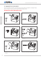
Benutzerhandbuch IUPS-401-Serie 3. Einbauanweisung 3.1 Modelle IUPS-401/-B5/-BB/-BC Durch den Einbau der IUPS in den Rechner an einer Stelle mit möglichst niedriger Temp eratur erlangen Sie eine Optimierung der Batterielebensdauer. Vor Beginn der Arbeit: Netzstecker ziehen! 1 Deutsch DSUB9-Verbindungskabel an der Rückseite der IUPS-401 anstecken und dort verschrauben. 2 IUPS-401 in Laufwerksschacht einschieben und mit beiliegenden Schrauben befestigen.
Benutzerhandbuch IUPS-401-Serie Externe USB-Anbindung Deutsch 1 Das Verbindungskabel der IUPS401 auf die 5-polige Stiftleiste und das Netzkabel der IUPS-401 am Slotblech aufstecken. 2 Das USB-Kabel vom Slotblech zum externen USB-Port stecken. Die Netzverkabelung vom Slot-blech zum Netzteil und Netzstecker verkabeln.
Benutzerhandbuch IUPS-401-Serie Interne USB-Anbindung 1 j k Deutsch Das Verbindungskabel der IUPS-401 auf die 5-polige Stiftleiste aufstecken k und das interne USB-Kabel von der 4-poligen Stiftleiste j auf das Mainboard stecken. 2 USB-Verkabelung Bitte überprüfen Sie die PINBelegung des internen USBKabels mit der PIN-Belegung auf Ihrem Mainboard. ACHTUNG: Die PIN-Belegungen müssen übereinstimmen! Eine Verpolung kann sowohl die USB-Schnittstelle als auch das Mainboard beschädigen! N.C.
Benutzerhandbuch IUPS-401-Serie 3.2 Modelle IUPS-401-B1/-B4/-BA/-B9 Durch den Einbau der IUPS in den Rechner an einer Stelle mit möglichst niedriger Temp eratur erlangen Sie eine Optimierung der Batterielebensdauer. Deutsch Vor Beginn der Arbeit: Netzstecker ziehen! 10 1. Netzstecker abziehen 2. Slotblech mit 5-pol. Steuerkabeleinbauen 3. 5-pol. Steuerkabel an der IUPS einstecken 4. Netzkabel der IUPS und das IUPS-Spezialkabel einstecken 5.
Benutzerhandbuch IUPS-401-Serie 4. Bediendisplay TEST TEST „Netzbetrieb“-LED: Die grüne LED leuchtet, wenn die Netzspannung anliegt. Die grüne LED blinkt bei Batterieladung. Deutsch TEST TEST „Back-up-Betrieb“-LED: Die rote LED blinkt, sobald die Netzspannung abgefallen ist und die IUPS die Stromversorgung übernommen hat. Der akustische Alarm ertönt alle 3 Sekunden. TEST „Batterie leer“-LED: Die rote LED blinkt (schnell), wenn die Batterie schwach ist.
Benutzerhandbuch IUPS-401-Serie 5. Schnittstelle und Software Deutsch 5.1 Modelle IUPS-401/-B5/-BB/-BC Die Schnittstelle an der Rückseite der IUPS kann über das im Lieferumfang enthaltene Spezialkabel (mit Platine) mit der USB-Schnittstelle des Computers verbunden werden. Durch die Installation der Software (UPSilon 2000), 1. kann bei Netzausfall eine Warnmeldung am Monitor angezeigt werden 2. können offene Dateien automatisch gesichert werden 3.
Benutzerhandbuch IUPS-401-Serie 6. Fehlerbehebung Fehler: Obwohl der Computer angeschlossen und eingeschaltet ist, zeigt die IUPS keine Funktion oder Alarm Möglicher Grund: Fehler bei der Installation Behebungsvorschlag: 1. Netzstecker ziehen 2. Überprüfen der gesamten Installation gemäß Anleitung Keine der LED‘s leuchtet Möglicher Grund: 1. Netzspannung fehlt 2. USV ist ausgeschaltet 3. Sicherung defekt 4.
Benutzerhandbuch IUPS-401-Serie Deutsch 7. Technische Daten Technische Daten Leistung 400 VA / 240 W Eingangsspannung 230 V AC ±15 % Eingangsfrequenz 50 / 60 Hz ±5 % Ausgangsspannung 230 V AC ±15 % Ausgangsfrequenz 50 / 60 Hz ±1 % Ladezeit Ca. 8 Std.
Benutzerhandbuch IUPS-401-Serie Modellübersicht ArtikelSchnittstelle Nummer IUPS-401 USB Lastsensor Abschaltung ≤ 33 W IUPS-401-B5 USB ≤ 20 W IUPS-401-BB USB ≤ 8W IUPS-401-BC USB ≤ 0W USV-Management-Software UPSilon 2000 und internes USBVerbindungskabel im Lieferumfang enthalten (WIN 98, NT, 2000, 2003, XP, ME, Vista, 7, Novell NetWare®, LINUX, FreeBSD, weitere auf Anfrage). Externes USB-Kabel 2.0, A-/B-Stecker/500 mm im Lieferumfang enthalten.
English User’s Manual IUPS-401-Series IUPS-401 with standard front panel IUPS-401 with changed, black front panel IUPS-401 series Integrated UPS 16
User’s Manual IUPS-401-Series General............................................................................................. 18 1.1 Contents of Delivery and Storage........................................ 18 1.2 Functional Description IUPS-401........................................... 18 1.3 Automatic ON / OFF Function................................................ 18 1.4 Overload Protection...................................................................... 19 1.5 Overtemperature Protection ....
User’s Manual IUPS-401-Series 1. General 1.1 Contents of Delivery and Storage Please check immediately upon reception whether the delivery is damaged in any way, for which packing damage may be an indication. The contents of delivery are: English 1 UPS unit IUPS | 1 Mains cable | 1 black front panel | 1 User‘s Manual IUPS-401/-B5/-BB/-BC: 1 Slot bracket with USB PCB 1 internal USB cable 1 external USB cable 2.
User’s Manual IUPS-401-Series 1.4 Overload Protection Load current is monitored by the IUPS. In case of an overload during battery mode the IUPS switches off. In case of an overload during mains mode a permanent sound is generated, which will stop when the overload is eliminated. 1.5 Overtemperature Protection When an overtemperature is detected by the internal temperature control, this is indicated by the red LED and an acoustic alarm sound. English 1.
User’s Manual IUPS-401-Series 2. Safety English Please observe the installation instruction and the following safety warnings. 1. Installation and connection of the IUPS must only be carried out by a qualified electrical technician. The relevant rules of electrical engineering must be observed. For powering the UPS units only the included power cord must be used. 2. The IUPS is only approved for installation and operation in a chassis.
User’s Manual IUPS-401-Series 3. Installation Instruction 3.1 IUPS-401/-B5/-BB/-BC To optimize the service life of the battery install the IUPS into the computer at a location with preferably low temperature. Disconnect mains before starting the installation! 1 English Connect DSUB9 connection cable at the back of the IUPS and fasten screws. 2 Push IUPS into the drive slot and fasten it with the included screws. 3 Mount the slot bracket with the USB interface to the PC.
User’s Manual IUPS-401-Series External USB connection English 1 Connect the connection cable of the IUPS-401 to the 5-pole pin-and-socket connector and the mains cable of the IUPS-401 to the slot bracket. 2 Connect the USB cable from the slot bracket to the external USB port. Connect mains wiring from the slot bracket to the power supply unit and to the mains plug.
User’s Manual IUPS-401-Series Internal USB connection 1 j k English Connect the connection cable of the IUPS-401 to the 5-pole pin and socket connector k and the internal USB cable from the 4-pole pin-and-socket connector j to the mainboard. 2 USB connection Please compare the pin assignment of the internal USB cable to the pin assignment of your PC mainboard. WARNING: The pin assignments must comply! A polarity reversal may damage the USB interface as well as the mainboard! N.C.
User’s Manual IUPS-401-Series 3.2 IUPS-401-B1/-B4/-BA/-B9 To optimize the service life of the battery install the IUPS into the computer at a location with preferably low temperature. English Disconnect mains before starting the installation! 24 1. Disconnect mains 2. Install slot bracket with 5-pole control cable 3. Connect 5-pole control cable at the IUPS 4. Connect mains cable of the IUPS and the special IUPS cable 5. Connect the IUPS mains cable with the power supply of the computer 6.
User’s Manual IUPS-401-Series 4. Display TEST TEST “Mains mode“ LED: The green LED is on when mains voltage is supplied. The green LED flashes during battery charge. English TEST TEST “Back-up mode“ LED: Combined with an acoustic alarm sound every 3 seconds the red LED flashes as soon as the IUPS has taken over power supply in case of mains power failure. TEST “Battery low“ LED: The red LED flashes (quickly) when the battery is low.
User’s Manual IUPS-401-Series 5. Interface and Software English 5.1 IUPS-401/-B5/-BB/-BC The interface at the back of the IUPS can be connected to the USB interface of the computer via a special cable (with PCB) which is included in delivery. When the software (UPSilon 2000) is installed, 1. 2. 3. 4. a warning message can be displayed at the monitor in case of mains power failure. open files can be saved automatically. the UPS can be switched off after the computer was shut down.
User’s Manual IUPS-401-Series 6. Troubleshooting Failure: Although the computer is connected and switched on, the IUPS shows neither function nor alarm Possible cause: Wrong installation Possible countermeasure: 1. Disconnect mains 2. Check the whole installation according to the instruction None of the LEDs is on Possible cause: 1. No mains voltage 2. UPS is switched off 3. Fuse is defect 4. No UPS function English Failure: Possible countermeasure: 1.
User’s Manual IUPS-401-Series English 7. Product Specifications Technical data Output power 400 VA / 240 W Input voltage 230 V AC ±15 % Input frequency 50 / 60 Hz ±5 % Output voltage 230 V AC ±15 % Output frequency 50 / 60 Hz ±1 % Charging time App.
User’s Manual IUPS-401-Series Model overview Article Interface No. IUPS-401 USB Load sensor switch off ≤ 33 W IUPS-401-B5 USB ≤ 20 W IUPS-401-BB USB ≤ 8W IUPS-401-BC USB ≤ 0W UPS management software UPSilon 2000 and internal USB cable included in delivery (WIN 98, NT, 2000, 2003, XP, ME, Vista, 7, Novell NetWare®, LINUX, FreeBSD, others on request). External USB cable 2.0, A-/B-plug / 500 mm included in delivery. Reboot function Article Interface No.
Irrtümer und technische Änderungen vorbehalten. Windows® ist ein eingetragenes Warenzeichen der Firma Microsoft Corp. Subject to errors and technical modifications. Windows® is a registered trademark of Microsoft Corporation. Stand/Issued: 21.11.2014 Bicker Elektronik GmbH Ludwig-Auer-Straße 23 86609 Donauwörth · Germany Tel. +49 (0) 906 70595-0 Fax +49 (0) 906 70595-55 E-Mail info@bicker.de www.bicker.