Manual Comfort Air Curtain Model DF Version 2.
en COMFORT AIR CURTAIN . . . Contents 1 Introduction 2 Installation 10 3 Operation 27 4 Maintenance 30 5 Faults 31 6 Service 36 en-2 1.1 1.2 1.3 1.4 1.5 2.1 2.2 2.3 2.4 2.5 2.6 2.7 2.8 2.9 3.1 3.2 3.3 3.4 4.1 4.2 5.1 5.2 5.3 6.1 6.2 6.3 6.4 6.
en 1 . . Introduction 1.1 About this manual This manual describes the installation, operation and maintenance of the Model DF Comfort air curtain. The manual also provides instructions and information about servicing. 1.2 How to read this manual 1.2.1 Marginal symbols used in the manual The following symbols are used in this manual: n Note: c Caution: Draws your attention to an important part of the text. If you do not perform this procedure or action correctly, you may damage the device.
en INTRODUCTION COMFORT AIR CURTAIN 1.2.2 Pictograms used on the unit and in the manual The following pictograms indicate potential risks or hazards. The same pictograms will also be found on the unit. Pictograms PICTOGRAM DESCRIPTION w You are entering an area of the unit containing live components. Accessible to qualified maintenance staff only. Exercise caution. w This surface or part can be hot. There is a risk of burns on contact. 1.2.
en DF MANUAL INTRODUCTION Mounting methods The free-hanging model is designed for free, visible installation above the door. The recessed model is designed for installation into a false ceiling or into an alcove where the air inlet may be at some distance from the unit itself. The cassette model is designed for installation above a false ceiling where the air inlet is close to the unit and the unit is easily accessible. Other versions and intended usage.
en INTRODUCTION COMFORT AIR CURTAIN Different combinations may arise. Explanation of the type code series DF air curtain range S small M medium L large unit size 100, 150, 200, 250 discharge length (cm) heating W hot water E electrical A zonder verwarming (Ambient) F fee-hanging model C cassette model R recessed model mounting method 1.3.3 Type plate The type plate can be found on top of the unit.
en DF MANUAL INTRODUCTION 1.3.5 Modifications and changes No changes or modifications may be made to the unit which could influence its safety without the approval of Biddle. The CE mark is no longer valid if the unit has been modified or changed in any way. 1.3.
en INTRODUCTION COMFORT AIR CURTAIN 1.4.2 Requisite skills • You must be technically qualified to install, maintain or service this equipment in accordance with local legislation, regulations and standards. • For operation in daily use, no special skills are required. • The unit is not intended for use by children or people with an intellectual disability. d Danger: NEVER attempt to perform installation, maintenance, or servicing work on the unit unless you are sufficiently qualified. 1.4.
en DF MANUAL INTRODUCTION c Caution: In exceptional situations, water may run out of the unit. Therefore do not place anything under the unit that could be damaged as a result. 1.5.2 Installation, maintenance and service d w Danger: The unit may be opened by qualified technical staff only. Warning: Perform the following actions before opening the unit: 1. Switch the unit off using the control panel. 2. Wait until the fans have stopped. 3. Allow the unit to cool down.
en 2. . 2.1 Installation Safety instructions w Warning: w Warning: Installation work on the unit may only be performed by qualified technical staff. Before you begin: read the safety instructions. See also: 1.5 "Safety instructions" on page 8 2.2 2.3 Delivery check • Check the unit and its packaging for correct delivery. Immediately report to the driver and to the supplier any damage caused in transit. • Make sure that all components and accompanying parts have been supplied.
en DF MANUAL INSTALLATION 6. Turn the mains power supply on and check that the unit is working properly. General instructions Some sections of this section only apply to certain models. Where this is the case, it will be indicated. If no specific model is referred to, the description applies to all models. n Note: Make sure you perform all installation operations that are required for your unit. Check the type plate and consult the manual if in doubt about the unit model and type.
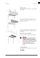
en INSTALLATION COMFORT AIR CURTAIN • Note the following dimensions: - w The unit must be at least as wide as the door opening (dimension b). Position the unit as near to the doorway as possible. Position the unit as close to the top of the door as possible. Warning: The minimum installation height (dimension h) is 1.8 m. The top of the unit may get hot. The unit should be placed with at least 25 mm ceiling clearance (dimension x).
en DF MANUAL INSTALLATION Dimensions of hole and suspension for cassette model SIZE TYPE DIMENSIONS a DF 100-C 1012 mm DF 150-C 1512 mm DF 200-C 2012 mm DF 250-C 2512 mm b all DF C 705 mm c DF 100-C 937 mm DF 150-C 1437 mm DF 200-C 1937 mm DF 250-C 2437 mm all DF C 641 mm d 2. Screw a lock nut 1 onto each threaded rod. 3. Attach the unit to the threaded rods. 4. Secure the unit by tightening the lock nuts 1. 2.5 Connecting the unit to the central heating system See also: 6.2.
en INSTALLATION COMFORT AIR CURTAIN 2.5.1 Particulars c Caution: The central heating system’s supply and return pipes must be attached to the correct connectors 1. The directions are indicated on the unit using arrows. • Keep the connectors 1 in place by using pliers when connecting the pipes. • Biddle recommends inserting a valve and a bleed on both pipes close to the unit. Application limitations for units with water heating Heating medium water with max. 20% glycol Max.
en DF MANUAL INSTALLATION 3. Connect the valve to Terminal Block 1 as shown in the electrical diagram. 4. Open the valve manually using the handle (Position ‘MAN’). 5. Fill and bleed the system. 6. Check the connections for leaks. 7. Return the handle to its starting position (Position ‘AUTO’). 2.6 Connecting the mains supply 2.6.1 Particulars For all models: w w Warning: The unit must be grounded. Warning: Connect the unit in accordance with the applicable local requirements.
en INSTALLATION COMFORT AIR CURTAIN • If the unit has not been fitted with a power cable and plug: Connect the unit to the mains using a power cable (not supplied). Maximum ratings are specified on the type plate. It must be possible to interrupt the power supply to the unit. You may choose to use either a plugged power supply cable or an isolation switch. Electrically-heated models: Warning: w Do not turn on the unit from the power supply. Use the control panel.
en DF MANUAL INSTALLATION MAXIMUM CURRENT ON TYPE PLATE L1, L2 OR L3 MAXIMUM FUSE VALUE A <= 80 A 100 A <= 102 A 125 A n Note: Multiple units may only be served by a common fuse is their total current consumption is less than 10A. 2.6.3 Connect the unit For units supplied without a mains power cable/plug only: w Warning: Only connect the unit if you are qualified to work on three-phase power systems. Make sure that the mains power supply has been turned off. 1.
en INSTALLATION 2.7 COMFORT AIR CURTAIN Installing the control panel and external controls 2.7.1 Control panel details Positioning • You may fix the control panel either to the wall or to a standard socket. Cabling n Note: Take the following into account, otherwise faults may occur: - Keep control cables away from electromagnetic fields and interference sources such as high-voltage cables and fluorescent-light starters. - Stretch control cables out or roll them up neatly.
en DF MANUAL INSTALLATION Control panel settings NO.
en INSTALLATION COMFORT AIR CURTAIN 2.7.4 Fault signal output A building management system (BMS) can be connected to the output. • The connector is located on the control PCB (HEALTHY connector). Output operation 24 VDC unit configured as a normal unit no power supply voltage temperature cut-out has turned the heating off or the unit is not being powered 2.7.5 Unit settings Optional unless otherwise stated Several dip switches 1 are located on the unit’s control PCB.
en DF MANUAL INSTALLATION Master settings Only if multiple units have been connected to a single control panel all units configured as normal units one unit configured as a master unit external control input only connected unit responds all units follow the master automatic temperature control each unit is independently controlled all units are controlled by the master 2.7.6 Multiple units operated from one control panel • A maximum of eight units may be connected to a single control panel.
en INSTALLATION COMFORT AIR CURTAIN You can connect one or more of these units to a single control panel in combination with other units. The following applies in this regard: • A unit with two control PCBs counts as two units. • A unit with two control PBCs is always the master unit. Units with a single control PCB must be configured as normal units. • If several units have two control PCBs, then one of these units is configured as the master unit.
en DF MANUAL INSTALLATION 4. Secure the cable in a tension-free state. The cable should protrude by approx. 9 cm. 5. Optional: Set the dip switches on the front plate. 6. Attach the control cable’s connector to the PCB. 7. Replace the front plate onto the rear plate. See also: 2.7.2 "Control panel settings" on page 18 6.5 "Biddle control cable composition" on page 40 2.7.
en INSTALLATION 2.8 COMFORT AIR CURTAIN Unit finishing 2.8.1 Edging For cassette models (Type DF C) only: 1. Make a hole in the ceiling for the unit. Dimensions of hole and suspension for cassette model SIZE TYPE DIMENSIONS a DF 100-C 1012 mm DF 150-C 1512 mm DF 200-C 2012 mm DF 250-C 2512 mm b all DF C 705 mm c DF 100-C 937 mm DF 150-C 1437 mm DF 200-C 1937 mm DF 250-C 2437 mm all DF C 641 mm d 2. Attach the angle sections using the screws supplied along the unit’s edges. 2.
en DF MANUAL INSTALLATION Discharge section hole dimensions B C SIZE TYPE DIMENSIONS a R 90 mm b 100-R 970 mm 150-R 1470 mm 200-R 1970 mm 250-R 2470 mm 2. Attach the two angle sections 1 to the unit along the discharge openings' edges using the screws supplied. 3. Extend the telescopic discharge duct 2 into the unit’s discharge opening until it reaches the required height. 4. Attach the discharge duct to the angle sections 1 using the screws supplied. c 2.
en INSTALLATION COMFORT AIR CURTAIN - Control cables between control panel and unit (or units); If applicable: external control components. 3. Switch the power supply on and/or plug in all connected units. 4. Start up the air curtain using the control panel. 5. Check that air is being blown out of all units across their full width. For water-heated models: 1. Check whether the heat exchanger and the control valve have been connected correctly. 2.
en 3 . . Operation 3.1 General All regular features can be operated from the control panel. The control panel allows you to: • start and stop the air curtain • set the required heating capacity • set the required room temperature • turn the heating on and off • adjust the air curtain’s airflow rate If multiple units have been connected to a single control panel, then settings apply to all units. 3.
en OPERATION 3.3 COMFORT AIR CURTAIN Adjusting the strength of the air curtain You can select three air curtain airflow settings: • Button 4: low fan • Button 5: medium fan • Button 6: high fan n 3.4 Note: To achieve maximum climate separation for minimum energy consumption, Biddle recommends selecting the lowest setting at which no draughts occur. Adjusting heating 3.4.1 Manual temperature control In manual mode, heating can be set to full or reduced capacity, or turned off.
en DF MANUAL OPERATION 3.4.2 Automatic temperature control In automatic mode, the unit measures the air inlet temperature and automatically selects the required heating setting to adjust the air temperature to the configured level. • Set the required temperature using Buttons 2 and 3 The LEDs display the temperature in a range from 18 °C to 25 °C. This temperature is measured at the unit’s air inlet and may deviate slightly from actual room temperature. 3.4.
en 4. . 4.1 Maintenance Cleaning the unit You may clean the exterior of the unit with a damp cloth and a domestic cleansing agent. Do not use any solvents. c 4.2 Caution: Make sure no water runs into the unit. Scheduled maintenance Biddle recommends that the following inspection and maintenance work is performed by an installer or other technical expert every year. en-30 • Check that the heat exchanger and the electrical heating element are clean. Settled dust may cause unpleasant smells.
en 5 . . Faults 5.1 Safety instructions d Danger: w Warning: Internal work may only be performed by qualified technical personnel. Before you begin: read the safety instructions. See also: 1.5 "Safety instructions" on page 8 5.2 Resolving simple problems If you suspect a fault, first try to resolve the problem using the below table. You need not be an expert for this. Solutions to simple problems PROBLEM LIKELY CAUSE WHAT TO DO There is a draught. Air curtain is turned off.
en FAULTS COMFORT AIR CURTAIN PROBLEM LIKELY CAUSE WHAT TO DO The unit is not working and the control panel LEDs are off. The unit is switched off. Turn the unit on. The unit has no power supply. Check the power supply: • Is the plug in the socket? • Is the isolator switch on? • Is there a voltage? The air curtain is switched off but is still working. The unit cools off automatically. This is not a fault. The unit will normally shut down automatically within two minutes. See also: 3.
en DF MANUAL FAULTS Fault rectification (for qualified technical staff only) PROBLEM POSSIBLE CAUSE RESOLUTION The control panel works normally but the unit does not respond. The fans are dead. 1. Check the fuse on the control PCB. 2. Check wiring between the control PCB and the fans. The connection between the control panel and the printed circuit board is not correct. 1. Check the control cable. 2. Check wiring between Connectors E and H and the unit’s control PCB.
en FAULTS COMFORT AIR CURTAIN PROBLEM POSSIBLE CAUSE RESOLUTION Not all connected units are working (or only partially). The control panel is not communicating with one or more connected units (or with one of the control PCBs in a dual-PCB unit). 1. Check if power is supplied to all connected units. 2. Check the control cables: • are they connected and free from breaks? • are they stretched out or rolled up neatly? • are they shielded from magnetic fields? 3.
en DF MANUAL FAULTS PROBLEM POSSIBLE CAUSE The unit (or part of the unit) is blowing cold air. The LEDs on the control panel are flashing. For electrically heated units: The temperature cut-out has turned the unit (or part of the unit) off to prevent overheating. RESOLUTION 1. Check and reset the temperature cut-out. 2. Check the fans. If one or more fans do not work, check: • the fan wiring; • control PCB connections This may indicate a seri• control PCB fuses ous fault that may be 3.
en 6. . 6.1 Service Safety instructions w Warning: w Warning: Servicing work on the unit may only be performed by qualified technical staff. Before you begin: read the safety instructions. See also: 1.5 "Safety instructions" on page 8 6.2 Access 6.2.1 Removing the front panel For free-hanging models only: 1. Remove the locking bolts 1 from the front panel 2. 2. Remove the front panel 2 from its suspension hooks 3.
en DF MANUAL SERVICE 6.2.2 Opening the unit For fee-hanging and recessed models with electrical heating (Types DF E-F, E-R) and models without heating (Types DF A-F, A-R): 1. Remove the front panel, if necessary. 2. Remove the inlet grille 4. For cassette models (Type DF C): 1. Push the inlet grille’s left- and right-hand latches towards each other. Use a screwdriver to do this. 2. Twist the inlet grille open and allow to hang freely. 3.
en SERVICE COMFORT AIR CURTAIN For all models: 1. Remove the screws along the edge of the panel. 2. Pull the panel a little forward and take it away. c Caution: The entire panel comes free once pulled forward – make sure it does not fall. 6.2.3 Removing the control PCB For all units: 1. Open the unit. For water-heated units and units without heating: 1. Remove the screws 1 on the top of the unit.
en DF MANUAL SERVICE 2. Remove the control PCB 2. 3. Disconnect all unit-connected connectors and grounded connections from the printed circuit board. For electrically heated units: 1. Disconnect all connectors and earth contacts connecting the unit and control PCB 1. 2. Remove the control PCB. See also: 6.2.2 "Opening the unit" on page 37 6.3 Fuses The unit’s control PCB has two fuses – 1 and 2. Values have been marked on the PCB. 6.
en SERVICE COMFORT AIR CURTAIN 6.4.1 Resetting the temperature cut-out 1. Turn the unit off. 2. Open the unit. 3. Push back the temperature cut-out pin 1. 4. Check unit connections. 5. Close the unit. 6. Check whether fans are working properly. 6.5 Biddle control cable composition The control system cable is made up as follows: en-40 • Connectors are Type 4P4C. • Connectors are untwisted, i.e. at both cable ends cores are connected to the same pin.
en DF MANUAL Manual version 2.
en Copyright and trademarks All information and drawings contained in this manual remain the property of Biddle and may not be used for any purpose other than that intended, photocopied, duplicated, translated and/or published without prior written permission from Biddle. Biddle’s name is a registered trademark belonging to Biddle BV. Warranty and liability Please refer to the sale & delivery terms & conditions for information about the warranty and liability.