
Specifications

DF MANUAL INSTALLATION
Manual version 2.0 (26-10-2012) en-19
en
Control panel settings
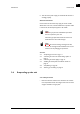
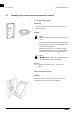
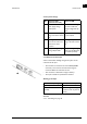
2.7.3 External control input
A door switch and/or building management system can be
connected to the input.
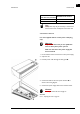
• The connector is located on the control PCB (INHIBIT
connector). This connector has been fed through to
Connector 1 on the outside of the unit.
• This connector is fitted with a bridge on delivery.
• The input is suitable for potential-free switches.
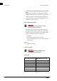
Working of the input
See also:
2.7.5 "Unit settings" on page 20
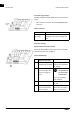
N
O.
POSITION OFF
(FACTORY SETTING)
POSITION ON
1 unit remains turned off
after supply voltage
interruption
unit continues running in
the same mode after
supply voltage interrup-
tion
2 fans continue running as
long as the unit is turned
on
fans do not run if heating
is not required
3 heating is turned off
once the set room tem-
perature has been
reached
heating is always on as
long as the unit is turned
on
4 display heating settings
using multiple LEDs
display heating settings
with only one LED (does
not affect operation)
contact closed (or bridged) unit operates normally
contact open unit remains off
resistor across contact
(3.3 kΩ)
unit working, but heating
remains turned off (summer
mode)