
Installation Guide
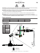

21
BIG ASS FAN 2025
WWW.BIGASSFANS.COM ©2014 DELTA T CORP. ALL RIGHTS RESERVED
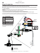
0RXQWWKHZDOOFRQWUROOHUVRWKDWWKHIDQLWFRQWUROVLVYLVLEOHIURPWKHFRQWUROOHUORFDWLRQ,QVWDOOWKHFRQWUROOHURQDÀDWVXUIDFHWKDWLV
UHDGLO\DFFHVVLEOHIUHHIURPYLEUDWLRQDQGZKHUHWKHUHLVDGHTXDWHGLVWDQFHIURPIRUHLJQREMHFWVRUPRYLQJHTXLSPHQW The controller
FDQEHVXUIDFHPRXQWHGWRDZDOORUPRXQWHGWRDFXVWRPHUVXSSOLHGMXQFWLRQER[
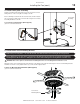
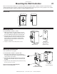
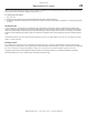
Mounting the Wall Controller
Wall Controller
Junction Box
(in wall,
customer-supplied)
CAT5
Cable
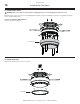
Mounting to a junction box
Note: A junction box is not supplied.
To mount the wall controller to a junction box:
1. 5HPRYHWKHZDOOFRQWUROOHU¶VIURQWFRYHUDVVHPEO\E\
XQVFUHZLQJWKHWZRVFUHZVRQWKHIURQWFRYHU6HWWKH
screws aside in a safe location.
2. 5RXWHWKH&$7FDEOHIURPWKHIDQLQWRWKHMXQFWLRQER[
DQGFRQQHFWLWWRWKH&$7FRQQHFWRURQWKHIURQWFRYHU
assembly.
3. 0RXQWWKHIURQWFRYHUDVVHPEO\WRWKHMXQFWLRQER[XVLQJ
the two (2) screws as shown.
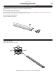
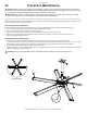
:DOO&RQWUROOHU+DUGZDUH%$)6XSSOLHG
[´2YDO+HDG6FUHZ
´FP
´FP
´FP
Dimensions
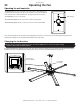
Wall Controller
Front Cover Assembly
Back Plate
(mounted to wall
with customer-
supplied screws)
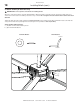
Mounting to a wall
To mount the wall controller to a wall:
1. Attach the back plate of the wall controller to the wall
using suitable customer-supplied mounting screws. Use
DQ\RIWKHDYDLODEOHPRXQWLQJKROHVRQWKHEDFNSODWH
2. Route the CAT5 cable from the fan through any of the
DYDLODEOHNQRFNRXWVRQWKHZDOOFRQWUROOHUDQGFRQQHFW
it to the CAT5 connector inside the controller. Note:
.QRFNRXWVDQGWKH&$7FDEOHDUHQRWVKRZQLQWKH
illustration on the right.
3. Snap the controller onto the back plate as shown.