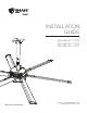
INSTALLATION GUIDE Big Ass Fan ® 2025 Big Ass Fan ® 3025 Big Ass Fan ® 3600 Manuel d’installation For help, call 855-490-3048 or email retail.help@bigasssolutions.
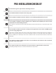
PRE-INSTALLATION CHECKLIST A structural engineer approved the mounting structure. I am familiar with the function of the safety cable. The fan will be installed so that the airfoils are at least 10 ft (3.05 m) above the floor. The fan will be installed so that the airfoils have a minimum of 2 ft (0.61 m) of clearance from obstructions and the building structure. The distance of the fan from the ceiling should be measured from the top of the airfoil tips to the ceiling.
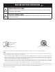
READ AND SAVE THESE INSTRUCTIONS WARNING AND CAUTION SYMBOL Indicates a hazard with a medium level of risk that could result in injury or death or damage to property if not avoided. ELECTRICAL WARNING SYMBOL Indicates an electrical hazard with a medium level of risk that could result in death or serious injury if not avoided. Installation Guide January 2016 Rev. E Original English Instructions Conforms to UL STD 507–Electric Fans Conforms to CSA C22.2 No.
IMPORTANT SAFETY INSTRUCTIONS TO REDUCE THE RISK OF FIRE, ELECTRIC SHOCK, OR INJURY TO PERSONS, OBSERVE THE FOLLOWING: CAUTION: Installation work and electrical wiring must be done by qualified person(s) in accordance with all applicable codes and standards. CAUTION: When cutting or drilling into wall or ceiling, do not damage electrical wiring and other hidden utilities. CAUTION: Use this unit only in the manner intended by the manufacturer. If you have questions, contact the manufacturer.
CONTENTS Introduction Safety Instructions........................................................................................................... ii About Big Ass Solutions...............................................................................................iv Technical Specifications Technical Specifications.................................................................................................1 Before Installing Your Fan Tools......................................................
You’ve made a great choice! Big Ass Fans® are an efficient, cost-effective and seriously cool way to stay comfortable and save energy all year long. More importantly, everything about your new fan—from the design of the motor to the angle of the airfoils—is based on extensive research, testing, and innovative engineering. It will keep you and your space comfortable for years to come. Questions or comments? We’d love to talk. Just call 855-490-3048 or email retail.help@bigasssolutions.
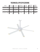
TECHNICAL SPECIFICATIONS Model Diameter Input Power Minimum Circuit Size Rated Current Maximum Speed Airfoil Length Big Ass Fan® 2025 7 ft (2.13 m) 110–125 VAC, 50/60 Hz, 1 Φ 10 A 5.1 A 198 RPM 35.5” (90.2 cm) Big Ass Fan® 3025 10 ft (3.05 m) 110–125 VAC, 50/60 Hz, 1 Φ 10 A 6.0 A 124 RPM 50.8” (129 cm) Big Ass Fan® 3600 12 ft (3.66 m) 110–125 VAC, 50/60 Hz, 1 Φ 10 A 4.1 A 85 RPM 62.8” (159.5 cm) WWW.BIGASSSOLUTIONS.COM © 2015 DELTA T CORP. ALL RIGHTS RESERVED.
BEFORE INSTALLING YOUR FAN Read the following pre-installation procedures and checks to ensure you have all necessary items for installation. Tools The main fan unit is heavy. A suitable means for lifting the weight of the fan, such as a scissor lift, at least two personnel, and the following tools will be required. Note: Depending on your application, additional tools may be required.
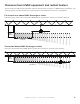
Clearance from HVAC equipment and radiant heaters The fan must be installed at the minimum distances shown below in relation to HVAC (Heating, Ventilation, and Cooling) systems. See the manufacturer’s requirements for the minimum clearance to combustibles. Fan located at or above HVAC discharge or intake If the fan is at the same level or above the HVAC diffuser, it must have a clearance of ≥1x fan’s diameter. Diameter: 7 ft (2.1 m) HVAC Diffuser ≥1x fan’s diameter 7 ft (2.
Hardware Verify you have all of the following required hardware before beginning the installation process. If you are missing any piece required for installation, contact Big Ass Fans Customer Service.
Parts Check that the fan boxes have all the parts before beginning installation. If you ordered multiple fans, be sure to keep the components of each fan together. The fans each have differently rated components that are not interchangeable. Do not remove the main fan unit from its protective packaging or place it on a flat surface prior to hanging it. Note: Illustrations are not to scale.
FAN DIAGRAM A. Upper Mount. Secures the fan to the mounting structure. B. Extension Tube. Extends the fan from the ceiling and provides a path for wiring. C. Upper Mounting Brace. Strengthens the upper mounting system. D. Cover Plate. Provides access to wiring and includes a fan status LED and a switch used to change the direction of fan rotation. The LED will flash an error code if there is a problem with the fan. See the Troubleshooting section for LED error codes.
INSTALLATION WARNING: The fan should not be installed unless the structure on which the fan is to be mounted is of sound construction, undamaged, and capable of supporting the loads of the fan and its method of mounting. A structural engineer should verify that the structure is adequate prior to fan installation.
1. Prepare the Bar Joists CAUTION: Do not install the fan from a single purlin, truss, bar joist, or junction box. CAUTION: Unsupported angle iron spans should not exceed 12 ft (3.7 m). CAUTION: The angle irons must be fastened to the roof structure at each end. Consult a structural engineer for installation methods not covered in this manual. A. Select proper angle irons Follow the table below when selecting angle irons for fan installation.
B. Pre-drill angle irons Drill two Ø7/16” (1.1 cm) holes exactly 5-1/2” (14 cm) apart in the centers of two angle irons. Measure the distance between the mounting points of the roof structure that the angle irons will span. Measure the same distance on the angle irons and drill Ø9/16” (1.4 cm) holes through each end of the angle irons. Drill holes in two angle irons if the span is 8 ft (2.4 m) or less. Drill holes in four angle irons if span is greater than 8 ft (2.4 m). Ø 9/16’’ (1.4 cm) A Ø 7/16’’ (1.
D. Fasten angle irons to roof structure mounting points Single Angle Iron Fasten the angle irons to the roof structure mounting points at each end with Grade 8 hardware as shown. Tighten the hardware so that it is snug, but do not torque until the fan has been mounted to the angle irons. We recommend orienting the angle irons so that the horizontal legs are facing each other (or the vertical legs are on the outside).
2. Route Wiring and Safety Cable into Extension Tube Note: To facilitate installation, Big Ass Fans recommends that the extension tube is horizontal with the rectangular access hole facing up during this step. Power Supply Cable Controller Input Cable A. Route the end of the controller input cable with the wiring harness on it (the end without the three loose wires) down into the top of the extension tube and out the rectangular access hole as shown. Access Hole B.
4. Attach Upper Mount to Angle Irons Secure the upper mount (with the extension tube and upper mounting brace attached) directly to the angle irons using the Mounting Hardware as shown. Consult the diagrams below for distances between the angle irons. Tighten the hardware so that it is snug, but do not torque. Mounting Hardware: a. (4) M10 x 40 mm Hex Head Cap Screw b. (8) M10 Flat Washer c. (4) M10 Nylock Nut 5-1/2” (14.6 cm) Side View 5-1/2” (14.6 cm) a b Note: Dashed lines represent angle irons.
5. Secure Safety Cable to Main Fan Unit CAUTION: Do not remove the main fan unit from its protective packaging or place it on a flat surface prior to hanging it. CAUTION: To prevent damage, avoid contact with the stator wires located on the bottom of the main fan unit. CAUTION: The main fan unit is heavy. Use caution when raising it. Raise the main fan unit directly from its packaging to the extension tube.
6. Attach Main Fan Unit to Extension Tube CAUTION: The main fan unit is heavy. Use caution when raising it. CAUTION: Be careful not to pinch the fan wiring between the extension tube and main fan unit during installation. CAUTION: Do not discard the main fan unit packaging and foam. It should be used if the fan is ever moved or relocated. Attach the main fan unit to the extension tube using the Main Fan Unit Hardware as shown. Note: Wiring not shown in the illustration below.
7. Tighten Hardware After attaching the main fan unit to the extension tube, tighten the following hardware to the specified torque. Tighten the Mounting Hardware to 25 ft·lb (33.9 N·m) using a 17 mm wrench and a torque wrench with a 17 mm socket. Allow the extension tube to hang freely and balance itself, and then tighten the Extension Tube Hardware to 25 ft·lb (33.9 N·m) using an 8 mm allen wrench and a torque wrench with a 17 mm socket.
8. Secure the Safety Cable ATTENTION The safety cable is a crucial part of the fan and must be installed correctly. If you have any questions, call Customer Service for assistance. A. Route the free end of the safety cable into one of the two holes in the Gripple®, and then pull the cable through the Gripple until the Gripple rests at the top of the extension tube. B. Wrap the safety cable tightly around the angle irons as shown, leaving as little slack as possible. C.
10. Install the Cover Plate Plug the remaining male wiring harness from the fan into the female wiring harness on the cover plate as shown. Ensure all wiring is tucked inside the extension tube, and then attach the cover plate to the extension tube using the Cover Plate Hardware as shown. a Cover Plate Hardware: a. (2) 8-32 x 1/2" Flat Head Screw 11.
12. Install the Lower Cover WARNING: Disconnect power to the fan before installing the lower cover mounting bracket and lower cover. Attach the lower cover to the lower cover mounting bracket using the Lower Cover Hardware as shown. Loosely attach all eight screws, and then tighten them. Lower Cover Hardware: a. (8) 6-32 x 3/8" Pan Head Screw a 13. Install the Trim Ring Snap the trim ring onto the lower cover as shown. 18 WWW.BIGASSSOLUTIONS.COM © 2015 DELTA T CORP. ALL RIGHTS RESERVED.
14. Mount the Wall Controller WARNING: To reduce the risk of electric shock, wiring should be performed by a qualified electrician! Incorrect assembly can cause electric shock or damage the motor and the controller! Hazard of electrical shock! WARNING: The installation of a Big Ass Fan must be in accordance with the requirements specified in this installation manual and with any additional requirements set forth by the National Electric Code (NEC), ANSI/NFPA 70-2014, and all local codes.
15. Wire the Fan and Wall Controller WARNING: To reduce the risk of electric shock, wiring should be performed by a qualified electrician! Incorrect assembly can cause electric shock or damage the motor and the controller! Make sure power wiring is routed to the installation site. Minimum supply circuit size is 10 A @ 110–125 V, 1 Φ. See Wiring Diagrams & Electrical Guidelines in the following section for instructions and guidelines on wiring your fan. 16.
C. Attach airfoils to main fan unit Attach the six airfoil retainers using the Airfoil Hardware. Moving clockwise around the fan hub, position the airfoil retainers end over end as shown. Hole A of the retainer should be positioned over top of Hole B. Do not tighten the bolts until all airfoil retainers have been attached! Tighten the bolts along the outer perimeter to 29 ft·lb (39.3 N·m) using a torque wrench with a 6 mm allen head socket.
WIRING DIAGRAMS & ELECTRICAL GUIDELINES WARNING: To reduce the risk of electric shock, wiring should be performed by a qualified electrician! Incorrect assembly can cause electric shock or damage the motor and the controller! Hazard of electrical shock! WARNING: The installation of a Big Ass Fan must be in accordance with the requirements specified in this installation manual and with any additional requirements set forth by the National Electric Code (NEC), ANSI/NFPA 70-2014, and all local codes.
Wiring: Fire Signal Relay WARNING: Improper installation can cause electric shock or damage to the motor and controller. A qualified electrician should perform the installation. If installing the fan in the United States, the fan must be installed per the following National Fire Protection Association (NFPA) guidelines: • The fan must be centered approximately between four adjacent sprinklers. • The vertical distance from the fan to the sprinkler deflector must be at least 3 ft (91.4 cm).
OPERATING THE FAN To start the fan, press the control knob on the wall controller. Note: The LED indicator at the top of the controller is lit when power is applied. The LED indicator will flash an error code if there is a problem with the fan. See the Troubleshooting section for LED error codes. LED Indicator To stop the fan, press the control knob. To increase fan speed, turn the control knob clockwise toward . To decrease fan speed, turn the control knob counterclockwise toward .
Moving at a low speed means less energy used for operation, translating into more energy savings year-round. Follow the procedures below to ensure the most efficient operation of your Big Ass Fan. To ensure proper fan rotation: 1. Turn on the fan. 2. Verify that the fan is rotating in the counterclockwise direction (when viewed from below). 3. If the fan is not rotating counterclockwise, reverse the fan direction. See the previous page for instructions on changing the direction of rotation.
PREVENTIVE MAINTENANCE WARNING: Before servicing or cleaning unit, switch power off at service panel and lock the service disconnecting means to prevent power from being switched on accidentally. When the service disconnecting means cannot be locked, securely fasten a prominent warning device, such as a tag, to the service panel.
ANNUAL MAINTENANCE CHECKLIST Fan Model: Fan Model: Fan Model: Serial #: Serial #: Serial #: Location: Location: Location: Date Initials Date Initials Date Initials
TROUBLESHOOTING WARNING: When servicing or replacement of a component in the fan requires the removal or disconnection of a safety device, the safety device is to be reinstalled or remounted as previously installed. CAUTION: Use this unit only in the manner intended by the manufacturer. If you have questions, contact the manufacturer.
Electrical troubleshooting Fan status LED definitions The fan direction selector switch and fan status LED are located on the cover plate at the bottom of the fan’s extension tube. Note: For information on changing the fan direction, see the Operating the Fan section.
Fan status LED troubleshooting LED code Description/Possible cause(s) Over Temperature The fan drive electronics have exceeded safe operating temperature limits. Output Device Failure The fan drive electronics have failed or output phase loss has occurred. Internal Communication Error The main fan drive has failed to respond to the command source (daughterboard, etc.). DC Buss Undervoltage Buss voltage has fallen below 255 VDC. DC Buss Over Voltage Buss voltage has exceeded 373 VDC.
Replacing fuses WARNING: Ensure power is disconnected before replacing fuses. CAUTION: Do not touch the fan’s electronics unless necessary! To replace the fuses on the main fan unit, remove the electronics cover from the fan as shown. The electronics cover is attached to the fan with four screws. Gently twist and pull out the appropriate fuse holder, and then replace the fuse. Reinstall the fuse holder, and then reattach the fan’s electronics cover. See below for fuse recommendations.
WARRANTY POLICY Congratulations on your purchase of a Big Ass Fan! We are delighted that you have chosen our product to improve the quality of your indoor or outdoor environment, and hope you’ll have much pleasure using the fan for years to come.
Technical Support is open from 8:00 a.m. to 5:00 p.m. Eastern Time, Monday–Friday, excluding major holidays. Every effort will be made to respond to all Technical Support requests within 24 hours of receipt. 3. Once the Technical Support Representative has received your warranty claim, a case will be processed. In order to process this case, please have the following information available: a. Your name, address, phone number, and installation address; b.
workmanship for a period of 90 days from the date of shipment to the customer, or for the remainder of the original warranty period, whichever is longer. 4. A service fee, parts replacement fee, and shipping charges may be imposed if any fan is returned for warranty service that is missing components or that has been modified in any way or when we determine that no warrantable failure occurred or defect exists.
6. Claims made for products that have not been paid for in full. 7. Damage caused by premises structural defects, structural movement or settlement, exposure to chemicals, salt water, acid rain or other corrosive elements, excessive humidity, and/or wind. 8. Normal changes to the finish caused by ordinary use or damage to non-factory applied finishes. 9. Damage or failure caused by subjection of the product to conditions outside its design limitations. 10.
WARRANTY RETURN INSTRUCTIONS We have received your request for replacement of a part that failed during normal use and which you believe to be covered under warranty. We are shipping this replacement part to you pursuant to your notice that you will be replacing the original part within 10 days. This replacement part is being shipped to you prior to our receipt of the item that failed, and prior to our evaluation of this part to determine the reasons for its failure and whether it is covered under warranty.
Warranty claim form instructions 1. Complete Warranty Claim Form and Responsibility Agreement (see following pages) and fax them to 859-9671695, Attn: Customer Service. These pages will be faxed back to you for your records. The Warranty Claim Form will include our acknowledgment and a Return Materials Authorization (RMA) number. Note: Do not return any item without first being assigned an RMA# by Big Ass Solutions Customer Service. 2.
WARRANTY CLAIM FORM Name (print): 800 Winchester Road Lexington, KY 40505 Phone: 855-490-3048 Fax: (859) 967-1695 www.bigassfans.com Signature: Company: Shipping Address: City/State/ZIP: Phone: Fax: Date of Purchase: Items Returned: Reason(s) for Returning Item (please provide detail, including length of time after fan had been in operation that problem was noticed, nature of problem, any attempts you made to remedy the problem, etc.
RESPONSIBILITY AGREEMENT 800 Winchester Road Lexington, KY 40505 Phone: 855-490-3048 Fax: (859) 967-1695 www.bigassfans.com To: Big Ass Solutions The undersigned understands and acknowledges receipt of the Warranty Claim Form and Instructions and agrees that Big Ass Solutions has the right, upon receipt of returned merchandise, to make final determination as to whether this merchandise should be replaced at no cost under Big Ass Solutions’ stated warranty policy.
CONTACT US Talk to a Big Ass Fan Expert. Call us at one of the numbers below or visit www.bigasssolutions.com Customer Service U.S.A & Rest of the World 2348 Innovation Drive Lexington, KY 40511 855-490-3048 retail.help@bigasssolutions.
GUIDE D'INSTALLATION Big Ass Fan® 2025 Big Ass Fan® 3025 Big Ass Fan® 3600 Pour obtenir de l'aide, appelez au 1 855 490-3048 ou envoyez un courriel à retail.help@bigasssolutions.
LISTE DE VÉRIFICATIONS AVANT L'INSTALLATION Un ingénieur en structure a approuvé la structure de montage. Je connais bien la fonction du câble de sécurité. Le ventilateur sera installé afin que les pales se situent à au moins 3,05 m (10 pi) du sol. Le ventilateur sera installé afin que les pales aient au moins 0,61 m (2 pi) de distance de tout obstacle et toute structure de bâtiment. La distance séparant le ventilateur du plafond devrait être mesurée à partir du dessus des pointes du pales et du plafond.
VEUILLEZ LIRE ET CONSERVER CES INSTRUCTIONS SYMBOLE D'AVERTISSEMENT ET DE MISE EN GARDE Indique un risque de niveau moyen pouvant causer des blessures, des dommages à la propriété ou même la mort, si non évité. SYMBOLE D'AVERTISSEMENT ÉLECTRIQUE Indique un risque électrique de niveau moyen pouvant causer des blessures sérieuses, ou même la mort, si non évité. Guide d'installation Janvier 2016 Ver.
IMPORTANTES CONSIGNES DE SÉCURITÉ POUR RÉDUIRE LE RISQUE D'INCENDIE, CHOC ÉLECTRIQUE OU DE BLESSURES CORPORELLES, VEUILLEZ SUIVRE LES DIRECTIVES SUIVANTES : MISE EN GARDE : le travail d'installation et le câblage électrique doit être effectué par une ou des personnes qualifiées conformément aux codes et aux normes applicables. MISE EN GARDE : lors du coupage ou du perçage dans un mur ou plafond, n'endommagez pas le câblage électrique et autres circuits encastrés.
TABLE DES MATIÈRES Introduction Consignes de sécurité......................................................................................................ii À propos de Big Ass Solutions......................................................................................iv Spécifications techniques Spécifications techniques................................................................................................ 1 Avant d'installer votre ventilateur Outils.......................................
Vous avez fait un excellent choix! Les ventilateurs Ass Fans® sont très efficaces et rentables, et constituent un moyen génial de rendre son environnement confortable et d'économiser de l'énergie toute l'année. Surtout, toutes les composantes de votre nouveau ventilateur – de la conception du moteur à l'angle des pales – sont inspirées d'études et de tests approfondis ainsi que d'une technique innovatrice. Votre espace sera désormais confortable pendant des années.
SPÉCIFICATIONS TECHNIQUES Modèle Diamètre Puissance d'entrée Taille minimale du circuit Courant nominal Vitesse maximale Longueur du pale Big Ass Fan® 2025 2,13 m (7 pi) 110 à 125 VCA, 50/60 Hz, 1 Φ 10 A 5,1 A 198 T/M 90,2 cm (35,5 po) Big Ass Fan® 3025 3,05 m (10 pi) 110 à 125 VCA, 50/60 Hz, 1 Φ 10 A 6,0 A 124 T/M 129 cm (50,8 po) Big Ass Fan® 3600 3,66 m (12 pi) 110 à 125 VCA, 50/60 Hz, 1 Φ 10 A 4,1 A 85 T/M 159,5 cm (62,8 po) WWW.BIGASSSOLUTIONS.COM © 2015 DELTA T CORP.
AVANT D'INSTALLER VOTRE VENTILATEUR Veuillez lire les procédures et effectuer les vérifications suivantes pour vous assurer que vous possédez tous les éléments nécessaires à l'installation. Outils Le corps du ventilateur est lourd. Un appareil de levage adéquat pour soulever le poids du ventilateur, comme une plate-forme élévatrice à ciseaux, au moins deux personnes et les outils suivants seront requis. Remarque : selon votre utilisation, des outils supplémentaires pourraient être requis.
☐☐ Si le montage du ventilateur se situe près d'un chauffage infrarouge ou radiant, Big Ass Solutions recommande de monter celui-ci plus loin que les espacements recommandés par le fabricant du système de chauffage, et à une hauteur égale ou supérieur à celle de l’écran de l'élément de chauffage, le contrôleur sur le côté opposé du système de chauffage.
Quincaillerie Assurez-vous d'avoir en main toute la quincaillerie nécessaire avant de commencer l'installation. Si des pièces nécessaires à l'installation sont manquantes, communiquez avec le servie à la clientèle Big Ass Fans.
Pièces Avant de commencer l'installation, assurez-vous qu'il ne manque aucune pièce dans les boîtes de ventilateurs. Si vous avez commandé plusieurs ventilateurs, assurez-vous de garder les composants avec son propre ventilateur. Les ventilateurs possèdent des composants cotés différemment et qui ne sont pas interchangeables. Ne retirez pas l'unité de ventilation principale de son emballage protecteur ou déposez-la sur une surface plate avant de l'accrocher.
SCHÉMA DU VENTILATEUR A. Support supérieur. Fixez solidement le ventilateur à la structure de montage. B. Tube de rallonge. Rallonge la distance entre le ventilateur et le plafond et offre un acheminement de câblage. C. Cale de montage supérieure. Solidifie le système de montage supérieur. D. Couvercle. Permet d'accéder au câblage et contient les lumières à DEL indiquant l’état du ventilateur, ainsi qu'un interrupteur permettant de modifier la direction de rotation du ventilateur.
INSTALLATION AVERTISSEMENT : le ventilateur ne devrait pas être installé ailleur que sur une structure robuste, non endommagée et capable de soutenir la charge du ventilateur et de ses méthodes de montage. Un ingénieur en structure devrait s'assurer que la structure est adéquate avant l'installation du ventilateur.
1. Préparer les poutrelles MISE EN GARDE : n'installez pas le ventilateur à partir d'un panne, d'un pont, d'une poutre ou d'une boîte de jonction. MISE EN GARDE : l'envergure des fers d'angle non soutenus ne doit pas excéder 3,7 m (12 pi). MISE EN GARDE : les fers d'angle doivent être fixés à la structure du toit à chaque extrémité. Consultez un ingénieur en structure pour des méthodes d'installation non couvertes dans ce manuel. A.
B. Pré-perçage des fers d'angle Percez deux trous de Ø 1,1 cm (7/16 po) à exactement 14 cm (5-1/2 po) de distance, centre à centre, des deux fers d'angle. Mesurez la distance entre les points de montage de la structure du toit sur lesquels les fers d'angle seront répartis. Mesurez la même distance sur les fers d'angle et percez des trous de Ø 1,4 cm (9/16 po) à chaque extrémité des fers d'angle. Percez des trous dans les deux fers d'angle si l'envergure est de 2,4 m (8 pi) ou moins.
D. Fixation des fers d'angle aux points de montage de la structure du toit Fer d'angle unique Fixez les deux fers d'angle aux points de montage de la structure du toit à chaque extrémité, en utilisant une quincaillerie de calibre 8, comme illustré. Serrez bien la quincaillerie, mais n'utilisez pas la clé dynamométrique tant que le ventilateur n'a pas été monté sur les fers d'angle.
2. Passer le faisceau de câblage et le cable de sécurité dans le tube de rallonge Remarque : pour faciliter l'installation, Big Ass Fans recommande que, pour cette étape, le tube de rallonge soit positionné de façon horizontale avec le trou d'accès rectangulaire, face vers le haut. Câble d'entrée du contrôleur Câble d'alimentation électrique A.
4. Fixer le support supérieur aux fers d'angle Fixez le support supérieur (avec le tube de rallonge et la cale de montage supérieure fixée ensemble) directement sur les fers d'angle en utilisant la quincaillerie de montage, comme montré. Consultez les schémas ci-dessous pour les distances à respecter entre les fers d'angle. Serrez la quincaillerie afin qu’elle soit bien ajustée, mais pas trop. Quincaillerie de montage : a. (4) vis à tête hexagonale M10 x 40 mm b. (8) rondelles plates M10 c.
5. Fixer solidement le câble de sécurité à l'unité de ventilation principale MISE EN GARDE : ne retirez pas l'unité de ventilation principale de son emballage protecteur ou déposezla sur une surface plate avant de l'accrocher. MISE EN GARDE : pour prévenir tout dommage, évitez tout contact avec les fils du stator situés dans le bas de l'unité principale de ventilation. MISE EN GARDE : l'unité de ventilation principale est lourde. Soyez prudents lorsque vous la soulevez.
6. Fixer l'unité de ventilation principale au tube de rallonge MISE EN GARDE : l'unité de ventilation principale est lourde. Soyez prudents lorsque vous la soulevez. MISE EN GARDE : faites attention de ne pas pincer le câblage du ventilateur entre le tube de rallonge et l'unité de ventilation principale lors de l'installation. MISE EN GARDE : ne jetez pas l'emballage ni la mousse de l'unité de ventilation principale. Ils devront être réutilisés si le ventilateur doit être déplacé ou relocalisé.
7. Serrer solidement la quincaillerie Après avoir fixé l'unité de ventilation principale au tube de rallonge, serrez solidement la quincaillerie suivante selon le couple indiqué. Serrez la quincaillerie de montage à un couple de 33,9 Nm (25 lb-pi) en utilisant une clé hexagonale de 17 mm et une clé dynamométrique avec une douille de 17 mm. Permettez au tube de rallonge de pendre librement et de s'équilibrer par lui-même.
8. Fixer solidement le câble de sécurité AVERTISSEMENT Le câble de sécurité constitue un élément essentiel du ventilateur et doit être posé correctement. Si vous avez des questions, communiquez avec le service à la clientèle pour obtenir de l'aide. A. Acheminez l'extrémité libre du câble de sécurité dans l'un des deux trous du Gripple® et tirez ensuite le câble dans le Gripple, jusqu'à ce que celui-ci soit appuyé sur le dessus du tube de rallonge. B.
10. Poser le couvercle Branchez le faisceau de câble mâle restant du ventilateur dans le faisceau de câble femelle du couvercle, comme montré. Assurez-vous que tout le câblage est bien inséré à l'intérieur du tube de rallonge. Fixez ensuite le couvercle au tube de rallonge en utilisant la quincaillerie du couvercle, comme montré. a Quincaillerie pour couvercle : a. (2) vis à tête plate 8-32 x 1/2 po 11.
12. Poser le couvercle inférieur AVERTISSEMENT : débranchez l'alimentation électrique du ventilateur avant d'installer le support de montage du couvercle inférieur et le couvercle inférieur. Fixez le couvercle inférieur au support de montage inférieur en utilisant la quincaillerie du couvercle inférieur, comme montré. Fixez lâchement les huit vis et serrez-les ensuite. Quincaillerie pour couvercle inférieur a. (8) vis à tête ronde bombée 6-32 x 3/8 po a 13.
14.
15. Câbler le ventilateur et le contrôleur mural AVERTISSEMENT : pour réduire le risque de choc électrique, le câblage devrait être effectué par un technicien qualifié! Un assemblage inadéquat pourrait causer un choc électrique ou endommager le moteur et le contrôleur! Assurez-vous que le câblage d'alimentation est acheminé au site d'installation. La dimension minimale du circuit d'alimentation est de 10 A @ 110 à 125 V, 1 Φ.
C. Fixer solidement les pales à l'unité de ventilation principale Fixez les six disques de retenue des pales en utilisant la quincaillerie pour pale. En tournant dans le sens des aiguilles d'une montre autour du moyeu de ventilateur, positionnez les extrémités des disques de retenue des pales comme montré. Le trou A du pale devrait être positionné au-dessus du trou B.
SCHÉMAS ÉLECTRIQUES ET DIRECTIVES ÉLECTRIQUES AVERTISSEMENT : pour réduire le risque de choc électrique, le câblage devrait être effectué par un technicien qualifié! Un assemblage inadéquat pourrait causer un choc électrique ou endommager le moteur et le contrôleur! Risque de choc électrique! AVERTISSEMENT : l'installation d'un ventilateur Big Ass Fan doit être effectuée conformément aux exigences précisées dans ce manuel d'installation et conformément à toutes autres exigences supplémentaires établies par
Câblage : Relais d'alarme d'incendie AVERTISSEMENT : une installation inadéquate peut causer un choc électrique ou endommager le moteur et les contrôles. Un électricien qualifié doit effectuer l'installation. Si l'installation du ventilateur est faite aux États-Unis, le ventilateur doit être installé conformément aux National Fire Protection Association (NFPA) : • Environ quatre arroseurs automatiques doivent entourer le ventilateur.
FONCTIONNEMENT DU VENTILATEUR Pour mettre en marche le ventilateur, appuyez sur le bouton du contrôleur situé sur le contrôleur mural. Remarque : le témoin à DEL, situé dans le haut du contrôleur, s'allume lorsqu'il est alimenté. Le témoin à DEL clignotera un code d'erreur si le ventilateur a un problème. Se reporter à la section Dépannage pour les codes d'erreurs du témoin DEL. Témoin à DEL Pour arrêter le ventilateur, appuyez sur le bouton du contrôleur.
Un déplacement à basse vitesse signifie moins d'énergie nécessaire pour fonctionner et se traduit donc en économies d’énergie sur une base annuelle. Suivez les procédures ci-dessous pour maximiser le fonctionnement de votre ventilateur Big Ass Fan. Pour assurer une rotation adéquate du ventilateur : 1. Mettez le ventilateur en marche. 2. Assurez-vous que le ventilateur tourne dans le sens anti-horaire (lorsque vous le regardez d'en dessous). 3.
ENTRETIEN PRÉVENTIF AVERTISSEMENT : avant d'entretenir ou de nettoyer l'unité, éteindre l'alimentation à partir du panneau d'entretien et verrouiller le débranchement du service pour éviter toute remise sous tension de façon accidentelle. Lorsqu'il est impossible de verrouiller le dispositif de débranchement du service, fixer solidement et bien à la vue un dispositif d'avertissement, comme une étiquette, sur le panneau d'entretien.
LISTE DE VÉRIFICATIONS POUR ENTRETIEN ANNUEL Modèle du ventilateur : Modèle du ventilateur : Modèle du ventilateur : No de série : No de série : No de série : Emplacement : Emplacement : Emplacement : Date Initiales Date Initiales Date Initiales
DÉPANNAGE AVERTISSEMENT : lorsque l'entretien ou le remplacement d'un composant dans le ventilateur nécessite le retrait ou le débranchement d'un dispositif de sécurité, le dispositif de sécurité doit être posé de nouveau ou remonté comme précédemment posé. MISE EN GARDE : utilisez cette unité pour les raisons pour lesquelles elle a été conçue par le fabricant. Si vous avez des questions, communiquez avec le fabricant.
Dépannage électrique Définitions des témoins à DEL de l’état du ventilateur L'interrupteur de sélection de direction du ventilateur et le témoin à DEL de l’état du ventilateur sont situés sur le couvercle, au bas du tube de rallonge du ventilateur. Remarque : pour tous renseignements concernant le changement de direction du ventilateur, se reporter à la section Fonctionnement du ventilateur.
Dépannage concernant les témoins à DEL de statut du ventilateur Code du témoin à DEL Description(s)/Cause(s) possible(s) Température trop élevée L'électronique d'entraînement du ventilateur excède les limites de température de fonctionnement sécuritaire. Défaillance d'un dispositif externe L'électronique d'entraînement du ventilateur est défaillante ou une perte de phase de sortie est survenue.
Remplacement des fusibles AVERTISSEMENT : assurez-vous que l'alimentation électrique est débranchée avant de remplacer des fusibles. MISE EN GARDE : ne touchez pas aux fonctions électroniques du ventilateur à moins que cela ne soit nécessaire! Pour remplacer des fusibles sur l'unité de ventilation principale, déposez le couvercle de l'électronique du ventilateur, comme indiqué. Le couvercle de l'électronique est fixé au ventilateur à l'aide de quatre vis.
POLITIQUE DE GARANTIE Félicitations d'avoir acheté le ventilateur Big Ass Fan! Nous sommes heureux que vous ayez choisi notre produit pour améliorer la qualité de votre environnement intérieur ou extérieur et espérons que celui-ci votre procurera beaucoup de plaisir pour les années à venir.
Le soutien technique est ouvert de 8 h à 17 h (HNE), du lundi au vendredi, excluant les jours fériés. Nous ferons tout en notre pouvoir pour répondre à toutes les demandes de soutien technique en moins de 24 heures suivant sa réception. 3. Lorsqu'un représentant du soutien technique reçoit votre réclamation de garantie, un dossier sera ouvert. Afin de traiter ce dossier, veuillez avoir en main les informations suivantes : a. vos nom, adresse, numéro de téléphone ainsi que l'adresse d'installation; b.
directs ou indirects ou anticipés par le client. 3. Lors du remplacement ou d'une réparation, Big Ass Solutions se réserve le droit d'utiliser des pièces de remplacement remises à neuf.
i. le défaut d'effectuer un entretien périodique, comme indiqué dans le manuel d'installation fourni par Big Ass Solutions.Les dommages consécutifs ou indirects subis par toute personne, entité ou structure résultant d’une violation de ces garanties, sauf si de tels dommages ne peuvent être exclus par la loi. 6. Les réclamations effectuées pour les produits n'ayant pas été payés en entier. 7.
INSTRUCTIONS POUR RETOUR SOUS GARANTIE Nous accusons réception de votre demande de remplacement d'une pièce défaillante lors d'une utilisation normale pour laquelle vous croyez être couvert par la garantie. Suite à votre demande, nous vous expédions cette pièce à condition que vous remplaciez la pièce d'origine d'ici 10 jours.
Instructions pour formulaire de réclamation de garantie 1. Veuillez remplir le formulaire de réclamation de garantie et d'entente de responsabilité (voir les pages suivantes) et télécopiez-les au 1 859 967-1695, à l'attention de : Service à la clientèle. Ces pages vous seront télécopiées plus tard afin que vous puissiez en conserver une copie pour vos dossiers. Le formulaire de réclamation de garantie inclut notre accusé de réception et un numéro d'autorisation de retour de marchandise (RMA).
800 Winchester Road Lexington, KY 40505 Téléphone : 1 855 490-3048 Télécopieur : 1 859 967-1695 www.bigassfans.
800 Winchester Road Lexington, KY 40505 Téléphone : 1 855 490-3048 Télécopieur : 1 859 967-1695 www.bigassfans.
NOUS CONTACTER Parler à un expert Big Ass Fan. Appelez-nous à l'un des numéros ci-dessous ou visitez www.bigasssolutions.com Service à la clientèle États-Unis et le reste du monde 2348 Innovation Drive Lexington, KY 40511 1 855 490-3048 retail.help@bigasssolutions.
*004465-01* 004465-01 REV. E 2425 Merchant St., Lexington, KY 40511 1 (877) BIG-FANS | WWW.BIGASSFANS.