
Installation Guide


WWW.BIGASSSOLUTIONS.COM © 2015 DELTA T CORP. ALL RIGHTS RESERVED.
5
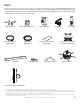
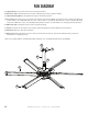
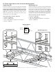
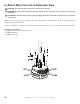
Parts
Check that the fan boxes have all the parts before beginning installation. If you ordered multiple fans, be sure
to keep the components of each fan together. The fans each have dierently rated components that are not
interchangeable. Do not remove the main fan unit from its protective packaging or place it on a flat surface prior
to hanging it. Note: Illustrations are not to scale.
1. The upper mounting brace strengthens the upper mounting system and must be installed inside the top of the extension tube.
2. The fire relay is provided for fans that will be installed in buildings with a fire sprinkler system. See the Wiring Diagrams & Electrical Guidelines section for fire relay wiring details.
3. The CAT5 cable connects the wall controller to the fan. One end plugs into the wall controller, and the other end plugs into the controller input cable. See the Wiring Diagrams
& Electrical Guidelines section for wiring details. A longer CAT5 cable can be used if needed (installer-supplied).
4. Two safety clips and two carabiners are provided for safety cable installation in locations where the top of the mounting structure is inaccessible. Contact Customer Service
if you need assistance installing the safety cable.
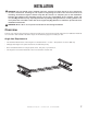
Extension Tube & Safety Cable
4
Upper Mount Upper Mounting Brace
1
Wall Controller Fire Relay
2
Cover Plate
20-ft (6-m) Power
Supply Cable
50-ft (15-m)
CAT5 Cable
3
5-ft (152-cm) Controller
Input Cable
Lower Cover, Mounting
Bracket, & Trim Ring
(6) Airfoils (6) Airfoil Tips (6) Airfoil Retainers Main Fan Unit