
Instructions / Assembly
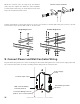

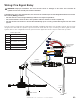

Relay Coil/Contact Details
White (X2) (-) C Blue
NC Yellow
Red (X2) (+) NO Orange
Coil: 20–32 VDC @ 20 mA
From main FACP
or NAC box, if
applicable
CAT5 Cable
Controller
Input Cable
To wall
controller
Wall Controller
WHITE
RED
RED
WHITE
ORANGE
BLUE
YELLOW
BLUE
YELLOW
WWW.BIGASSFANS.COM © 2015 DELTA T LLC ALL RIGHTS RESERVED.
23
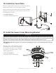
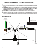
Wiring: Fire Signal Relay
WARNING: Improper installation can cause electric shock or damage to the motor and controller. A
qualified electrician should perform the installation.
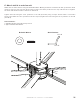
If installing the fan in the United States, the fan must be installed per the following National Fire Protection
Association (NFPA) guidelines:
• The fan must be centered approximately between four adjacent sprinklers.
• The vertical distance from the fan to the sprinkler deflector must be at least 3 ft (91.4 cm).
• The fan must be interlocked to shut down immediately upon receiving a waterflow signal from the alarm
system.
The fire relay is provided for fans that will be installed in buildings that have a fire sprinkler system. The fire relay
integrates the fan with the sprinkler system and shuts down the fan upon receiving an alarm signal from the
system. Note: In the configuration shown, power must be applied to the fire relay to enable fan operation.
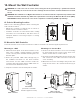
Controller Input Cable
White +0–10 VDC Speed Ref.
Brown Not Used
Orange Status LED (+)
Yellow
Run Enable
Closed: Enable; Open: Disable
Blue
Green Status LED (-)
Red +10 VDC Supply
Black DC Common