OWNER’S MANUAL 1500-LB. ENGINE STAND Item: T26801 Questions, problems, missing parts? Before returning to your retailer, contact our customer service department at www.torin-usa.com/support. Read carefully and understand all ASSEMBLY AND OPERATION INSTRUCTIONS before operating. Failure to follow the safety rules and other basic safety precautions may result in serious personal injury.
SAFETY MARKINGS WARNING! 1. Study, understand, and follow all instructions before operating this device. 2. Do not exceed rated capacity. 3. Use only on hard, level surfaces, with less than 3 degrees of slope. 4. Center load on mounting plate. 5. Mount and support only on areas of the engine as specified by the vehicle manufacturer. 6. Lock mounting plate rotating mechanism before applying a load. 7. Lock the wheels/casters before working on the engine. 8.
4. Attach main post (10) to the rear support beam (13) with bolt (11) (19), washer (5), spring washer (6) and nut (7). 5. Remove the cap (14) from the front leg (27), Attach caster (28) to front leg (27) with washer (5) spring washer (6) and nut (7), put the cap (14) to the front leg (27). 7.
8. Attach head assembly(3) to mounting arms (4) with bolt (2), washer (5),spring washer(6) and nut (7). 9. Insert head assembly (3) into the hole of the main post (10). Line up the hole in the head assembly (3) and the main post (10), and assembly them by inserting the head locking pin (1). 10. Tight all the screws. BEFORE USE WARNING: Failure to heed these warnings may result in personal injury, property damage and/or death.
OPERATION 1. With the mounting arms (4) loosened, use the correct size engine bolts to attach to the engine. (ENGINE BOLTS ARE NOT INCLUDED WITH ENGINE STAND.) 2. Use the stop pin (1) to lock the head plate assembly with the head collar. Engine Engine Bolt 3. Make sure the engine is centered and level on the head plate assembly, then tighten the mounting arms to the engine first, and then tighten the mounting arms to the head assembly. 4.
MAINTENANCE INSTRUCTIONS Maintain your equipment. It is recommended that the general condition of any equipment be examined before it is used. Keep your equipment in good repair by adopting a program of conscientious repair and maintenance. Have necessary repairs made by qualified service personnel. • Follow the maintenance instructions carefully to keep your equipment in good working condition. Never perform any maintenance on the equipment while it is under a load. a.
ASSEMBLY DIAGRAM Ref. Part# Description Qty No. Part Description 15 GB5782-M8X65 Hex head bolt M8x65mm(Metric-class 8.8) 2 16 T26801.7 Wheel 2 17 GB93-M8 Spring washer M8 2 18 GB6170-M8 Nut M8 2 19 Hex head bolt M12x70mm(Metric-class 8.8) 4 15 20 QLQD2B-3 Roundwire snap ring Ø1.4x26mm 1 1 21 T26801.9(ASM) Caster assembly with screw 2.5" 1 22 Washer M10 1 23 Spring washer M10 1 24 Nut M10 1 T2680125 4(ASM) Position pin 1 26 Fortable beam 1 1 T26801.
WARRANTY NOTICE This equipment is covered under a 1-year limited warranty when used as recommended. Only those items listed with a Part # are available for purchase. For assistance with the operation or the availability of replacement parts, contact our Parts and Warranty Department at www.torin-usa.com/support. Please have available a copy of your receipt, the model number of the product, serial number, and specific details regarding your question.
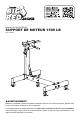
MANUEL DU PROPRIÉTAIRE SUPPORT DE MOTEUR 1500 LB Item: T26801 AVERTISSEMENT! Questions, problèmes, pièces manquantes? Avant de retourner voir votre fournisseur, appelez notre service à la clientèle au www.torin-usa.com/support. Lisez attentivement et comprenez toutes les DIRECTIVES DE MONTAGE ET DE FONCTIONNEMENT avant l’utilisation. Vous pouvez subir des blessures graves si vous ne vous conformez pas à ces règles et autres précautions de sécurité.
MARQUAGES DE SÉCURITÉ AVERTISSEMENT! 1. Étudiez, comprenez et suivez toutes les instructions avant de faire fonctionner cet appareil. 2. Ne dépassez pas la puissance nominale. 3. Utilisez seulement sur des surfaces dures et plates, avec moins de 3 degrés d’inclinaison. 4. Centrez la charge sur la plaque de fixation. 5. Montez et supportez uniquement dans les parties du moteur spécifiées par le fabricant du véhicule. 6. Bloquez le mécanisme de rotation de la plaque de fixation avant de le charger. 7.
4. Attachez le montant principal (10) à la colonne de support arrière (13) avec boulon (11) (19), rondelle (5), rondelle élastique (6) et écrou (7). 5. Enlevez le bouchon (14) du pied avant (27), Attachez les roulettes (28) au pied avant (27) avec rondelle (5), rondelle élastique (6) et écrou (7), mettez le bouchon (14) sur le pied avant (27). 7. Attachez le montant principal (10), la colonne pliable (26) avec boulon (12), rondelle (22) rondelle élastique (23) et écrou (24).
8. Attachez l’assemblage de la plaque frontale (3)aux bras de montage (4) avec boulon (2), rondelle (5),rondelle élastique (6) et écrou (7). 9. Insérez l’assemblage de la plaque frontale (3) dans le trou du montant principal (10). Alignez le trou dans l’assemblage de la plaque frontale (3) et le montant principal (10), et assemblez-les en y insérant la goupille d’arrêt (1). 10. Serrez toutes les vis.
OPÉRATION 1. Avec les bras de montage desserrés (4), utilisez la taille correcte de boulons de fixation de moteur afin d'attacher les bras au moteur.(LES BOULONS DE FIXATION DE MOTEUR NE SONT PAS COMPRIS AVEC LE SUPPORT DE MOTEUR.) 2. Utilisez la goupille de butée (1) afin de bloquer l’assemblage de la plaque frontale avec l’embase de la plaque frontale. Moteur Moteur Boulon 3.
INSTRUCTIONS D’ENTRETIEN • Entretenez votre équipement. Il est recommandé d’examiner les conditions générales des équipement, avant de les utiliser. Gardez votre équipement en bon état, adoptez un plan d’entretien et de réparation, consciencieusement. Appelez des services certifiés et qualifié pour les réparations de votre appareil. • Suivez soigneusement ces instructions d’entretien pour conserver votre appareil en bonnes conditions de travail. N’entretenez jamais votre appareil pendant un levage. a.
ASSEMBLY DIAGRAM No. Partie Description Qte 1 T26801.1(ASM) Assemblage de la goupille de butée 1 2 GB5782 Boulon à tête hexagonale M12x55mm (Classe 8.8) 4 3 T26801.2 Assemblage de la plaque frontale 1 4 T23401.1 Bras de montage 4 5 GB95-12 Rondelle M12 15 6 GB93-12 Rondelle élastique M12 15 7 8 9 GB6170-M12 T26801.4(ASM) T32002F-1 Écrou M12 Assemblage de la plaque frontale No. Partie Description Qte 15 GB5782-M8X65 Boulon à tête hexagonale M8x65mm (Classe 8.
GARANTIE Ce équipement est couvert par une garantie limitée d’un (1) an lorsqu’il est utilisé conformément aux recommandations. Seuls ces articles énumérés à l’aide d’un numéro de pièce sont disponibles pour achat. Pour obtenir de l’aide quant au fonctionnement ou à la disponibilité des pièces de rechange, communiquez avec notre Service des pièces et de garantie au www.torin-usa.com/support.
MANUAL DEL PROPIETARIO SOPORTE DE MOTOR PARA 1500 LB. Item: T26801 ADVERTENCIA ¿Alguna pregunta o problema? ¿Le faltan piezas? Antes de recurrir a su distribuidor, llame a nuestro departamento de atención al cliente al www.torin-usa.com/support. Lea atentamente y entienda todas las INSTRUCCIONES DE ENSAMBLAJE Y OPERACIÓN antes de utilizar el producto. Si no respeta las normas de seguridad y otras precauciones básicas de seguridad, pueden producirse lesiones personales graves.
MARCAS DE SEGURIDAD ADVERTENCIA 1. Estudie, comprenda y siga todas las instrucciones antes de operar este dispositivo. 2. No exceda la capacidad nominal. 3. Úselo solo sobre superficies duras y niveladas, con una pendiente menor a 3 grados. 4. Centre la carga sobre la placa de montaje. 5. Monte y sostenga el motor exclusivamente por las áreas del especificadas por el fabricante del vehículo. 6. Trabe el mecanismo giratorio de la placa de montaje antes de aplicar la carga. 7.
4. Sujete el poste principal (10) a la viga de soporte trasero (13) con pernos (11)(19), arandelas (5), arandelas de resorte (6) y tuercas (7). 5. Remueva la tapa (14) de la pata delantera (27). Sujete las ruedecillas giratorias(28) a la pata delantera (27) con arandelas (5), arandelas de resorte (6) y tuercas(7), y coloque la tapa(14) en la pata frontal(27). 7. Asegure el poste principal (10) a la viga de plegado (26)con pernos (12), arandelas (22) arandelas de resorte (23) y tuercas (24).
8. Sujete ensamblaje del cabezal(3) ta los brazos de montaje(4) con el perno (2), la arandela (5),la arandela de resorte(6) y la tuerca(7). 9. Inserte el ensamblaje del cabezal (3) en el orificio del poste principal (10). Alinee el orificio en el ensamblaje del cabezal (3) con el orificio del poste principal (10) y ensámblelos entre sí insertando el pasador de bloqueo del cabezal(1). 10. Apriete todos los tornillos.
OPERACIÓN 1. Con los brazos de montaje(4) flojos, utilice los pernos de motor del tamaño correcto para sujetar los brazos al motor. (LOS PERNOS DE MOTOR NO SE INCLUYEN CON EL SOPORTE DEL MOTOR). 2. Use el pasador de tope (1) para trabar el ensamblaje de la placa del cabezal con el collarín del cabezal. Motor Perno Motor 3.
INSTRUCCIONES DE MANTENIMIENTO Manteniendo su equipo. Se recomienda examinar la condición general de cualquier equipo antes de usarlo. Mantenga su equipo bien reparado adoptando un programa de reparación y mantenimiento a conciencia. Haga que todas las reparaciones necesarias sean hechas por personal de servicio calificado. • Siga cuidadosamente las instrucciones de mantenimiento para mantener su equipo en buenas condiciones de trabajo.
ASSEMBLY DIAGRAM Nº Parte No. Descripción 15 GB5782-M8X65 Perno cabeza hexagonal M8x65mm (Métrico-clase 8.8) 2 16 T26801.7 Rueda 2 17 GB93-M8 Arandela de resorte M8 2 18 GB6170-M8 Arandela M8 2 19 Perno cabeza hexagonal M12x70mm (Métrico-clase 8.8) 4 15 20 QLQD2B-3 Anillo de retención de alambre Ø1.4x26mm 1 T26801.4(ASM) Ensamblaje central 1 21 T26801.9(ASM) Caster assembly with screw 2.
AVISO DE GARANTÍA Este equipo está cubierto por una garantía limitada de 1 año cuando se utiliza según lo recomendado. Únicamente los artículos que figuran con un número de pieza están disponibles para compra. Para obtener ayuda con la operación o la disponibilidad de las piezas de repuesto, comuníquese con nuestro departamento de piezas y garantía al www.torin-usa.com/support.
Torin Inc. 4355 E. Brickell Street Ontario, CA USA www.torin-usa.