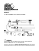
OWNER’S MANUAL T71001L 10-TON HYDRAULIC RAM SYSTEM WARNING: Questions, problems, missing parts? Before returning to your retailer, call our customer service department at 1-888-448-6746, 8 a.m.- 5 p.m., PST, Monday-Friday. Read carefully and understand all ASSEMBLY AND OPERATION INSTRUCTIONS before operating. Failure to follow the safety rules and other basic safety precautions may result in serious personal injury.
IMPORTANT Before You Begin Register This Product. For future reference, record the model name, model number, date of manufacture and purchase date of this product. You can find this information on the product. Model Name _________________________ Model Number _________________________ Date of Manufacture _________________________ Date of Purchase _________________________ OWNER / USER RESPONSIBILITY DO NOT OPERATE OR REPAIR THIS PRODUCT WITHOUT READING THIS MANUAL.
INTENDED USE Portable Power Kits are designed to be used for pushing, spreading, and pressing of vehicle body panels as well as various component parts and assemblies. TECHNICAL SPECIFICATIONS Description Manual 10 Ton 8,939 20-7/8 in. 14-15/16 in. 20 7/16in. x 5 3/16in. x 5 ½ in. Yes Application Capacity Operating PSI Max. Lift Height Min.
IMPORTANT SAFETY CONSIDERATIONS PLEASE READ THESE INSTRUCTIONS CAREFULLY. NOTE THE SAFETY INSTRUCTIONS AND WARNING. USE THE PRODUCT CORRECTLY AND WITH CARE FOR THE PURPOSE OF WHICH IT IS INTENDED. FAILURE TO DO SO MAY CAUSE DAMAGE TO PROPERTY AND/OR SERIOUS PERSONAL INJURY. PLEASE KEEP THIS INSTRUCTION MANUAL SAFE FOR FUTURE USE. We’ve done all we can to assure this equipment offers the outmost in safety, but you have to do your part.
WARNING: To reduce the risk of personal injury and/or property damage, ensure that the rated working pressure of each pressurized attachment be equal to or greater than the rated working pressure developed by the hydraulic pump. Always check connections before using. Alteration of these products is strictly prohibited.
GENERAL SAFETY RULES Save these instructions. For your safety, read, understand, and follow the information provided with and on this product before using. The owner and/or operator of this equipment shall have an understanding of safe use/operating procedures before attempting to use. The owner and/or operator shall be aware that the use of this product may require special skills and knowledge.
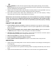
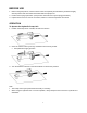
ASSEMBLY To assemble Hydraulic Ram, Pump Unit, and Attachments 1. Unscrew and save the End Plugs located on the ends of the Hose and Hydraulic Ram. 4. To attach the Rubber Head, the Extension Bars, the Male Connector, and the Flat Base to the Hydraulic Ram. 2. Securely screw the Hose into the Hydraulic Ram. 5. To attach the Spreader Wedge to the Pump Unit. 6. 3. Insert the Pump Handle into the receptacle located at the top of the Pump Unit. 7 For other attachment combinations.
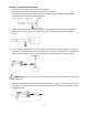
SYSTEM AIR PURGE PROCEDURE Perform the following Air Purge Procedure to remove any air that may have been introduced into the hydraulic system as a result of product shipment and handing. This step is to be completed without any load pressure. 1. Firmly close the Release Valve by turning it clockwise. 2. Press the tip of the Hydraulic Hose Coupling against a hard surface and pump the pump handle. 3.
BEFORE USE 1. Before using this product, read the owner's manual completely and familiarize yourself thoroughly with the product and the hazards associated with its improper use. 2. Perform the air purge procedure. (See previous instructions for system purge procedure.) 3. Inspect before each use. Do not use if bent, broken or cracked components are noted. OPERATION To Operate the Hydraulic Pump Unit 1. Position the Pump Unit on a stable, flat and level surface. 2.
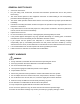
Example: To Repair Frame Damage 1. Determine which direction the frame needs to straighten. 2. Remove any obstructions that could be damaged or are in the way. 3. Connect the Flat Base to the stationary side of the Hydraulic Ram and connect the appropriate attachment to the pushing end of the Stroke Ram. 4. Position the Hydraulic Ram so that the Flat Base is resting against a frame member opposite the damaged area. It must also be in line with the direction in which the damaged area needs to be pushed. 5.
Example: To Repair Sheet Metal Damage 1. Determine which direction the body panel should be moved. 2. Remove any obstructions that could be damaged or are in the way. 3. Connect the appropriate attachments to the Hydraulic Ram. Note: When repairing larger body panel dents such as a piece of sheet metal, dented door, fender or suggested use is the Rubber Head. 4. Attachment must also be in line with the direction in which the damaged area needs to be pushed.
Example: To Use the Spreader Wedge 1. Determine which direction part needs to be bent. 2. Remove any obstructions that could be damaged or are in the way. 3. Place Spreader Wedge so that the hinged arm is resting against the part to be moved and the stationary arm is resting against a non-movable base. Hold the Spreader Ram in position and apply the Pump Unit pressure.
MAINTENANCE INSTRUCTIONS If you use and maintain your equipment properly, it will give you many years of service. Follow the maintenance instructions carefully to keep your equipment in good working condition. Never perform any maintenance on the equipment while it is under a load. Inspection You should inspect the product for damage, wear, broken or missing parts (e.g.: pins) and that all components function before each use. Follow lubrication and storage instructions for optimum product performance.
TO ADD OIL TO HYDRAULIC PUMP UNIT: TO REPLACE OIL TO HYDRAULIC PUMP UNIT : After extensive use, the hydraulic oil supply should be replaced to ensure longer equipment life. 1. Set Pump Unit upright on a level surface. 1. Set Pump Unit flat on a level surface. Remove the screw with its attached dipstick. 2. Remove the Screw with its attached dipstick. 2. Turn the Pump Unit on its side so that old oil will drain from the oil fill hole. 3. Add 0.24 Qts (approximately 7.68oz./ 220ml) of oil.
ADDITIONAL WARNINGS: DO NOT USE MOTOR OIL IN THE JACK. ONLY USE ANTI-FOAMING JACK OIL. ALWAYS USE A GOOD GRADE HYDRAULIC JACK OIL. DO NOT USE HYDRAULIC BRAKE FLUID, ALCOHOL, GLYCERINE, DETERGENT, MOTOR OIL OR DIRTY OIL. USE OF A NON-RECOMMENDED FLUID CANCAUSE DAMAGE TO A JACK. AVOID MIXING DIFFERENT TYPES OF FLUID AND NEVER USE BRAKE FLUID, TURBINE OIL, TRANSMISSION FLUID, MOTOR OIL OR GLYCERIN.
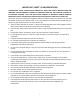
TROUBLESHOOTING Ram won’t lift load Ram won’t maintain hold Ram won’t lower after unloading Ram won’t extend to full stroke Poor performance 16 CAUSES AND SOLUTIONS Releases valve not tightly closed. Firmly close release valve. Weight Capacity Exceeded. Air is in the hydraulics. Purge air from system. Low oil level. Add oil as required. Oil reservoir is overfilled: Drain excessive oil. Lubricate moving parts.
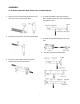
ASSEMBLY DIAGRAM ASSEMBLY PARTS LIST Index # 1 2 3 4 5 6 7 8 9 10 11 12 13 14 15 Description Extension Tube 27” Extension Tube 18” Extension Tube 10” Extension Tube 5” Pump Unit Ram Assembly Spreader(1000lb.Capacity) Serrated Saddle Combination Head Wedge Head(offset) Rubber Head Plunger Toe(offset) Ram Toe(offset) Flat Base Male Connector Part Number QF10.10(27”) QF10.10(18”) QF10.10(10”) QF10.10(5”) QF10.0(PUMP) QF10.0(RAM) QF4.7 QF10.7a QF10.6 QF10.5 QF10.8 QF10.2a QF10.4 QF10.3a QF10.9 17 Qty.
PUMP ASSEMBLY 18
PUMP ASSEMBLY PARTS LIST Index # P1 P2 P3 P4 P5 P6 P7 P8 P9 P10 P11 P12 P13 P14 P15 P16 P17 P18 P19 P20 P21 P22 P23 P24 P25 P26 P27 P28 P29 P30 P31 P32 P33 P34 P35 P36 Description Base Filter Seal Reservoir Top Nut Pump Foot Nut M18 O-Ring 7.7X1.9 Dipstick Ball Φ5 Ball Φ8 Spring Screw M10X1 Release Valve Stem Seal O-Ring 18X3.55G Seal Clamping Nut O-Ring 11.6x2.65 Seal Piston Socket Piston Pin Pin Φ10 Snap Ring 10 Handle Handle Grip Hose Coupling Dust Cap Ball Φ4 Spring Plunger Spring O-Ring 5.8X2.
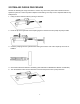
HYDRAULIC CYLINDER RAM ASSEMBLY 20
HYDRAULIC CYLINDER RAM PARTS LIST Index # 1 2 3 4 5 6 7 8 9 10 11 12 13 14 15 16 17 18 Description Cylinder Retainer Nut M48X1.5 Protecting Cap Spring Nut M6 Screw M6X30 Ring Snap Dust Cup Y-Ring Seal Cap Piston Cup O-Ring 24.5X3.1 Ram Spacing Ring Ring Snap Protecting Cap Screw M6X20 Coupling Valve Part Number QF10.1 QF10-14 QF10-15 T71003LT-5 GB41-86 GB70-85 T71003LT-8 QF4-34 TF1008G-10 TF1008G-11 T71003LT-7 QF10-9 T71003LT-6 T71003LT-9 QF10-12 QF10-11 GB70-85 QF4.6-1 Qty.
REPLACEMENT PARTS Consumers for replacement parts and technical questions call us Monday – Friday between 8am and 5:00pm EST at 1-888-448-6746. www.torinjacks.com Please contact our Customer Service Department with any questions you may have concerning parts, use, or maintenance. Not all equipment components are available for replacement, but are illustrated as a convenient reference of location and position in the assembly sequence. Contact Customer Service for equivalent component.