
User Manual


21
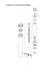
HYDRAULIC CYLINDER RAM PARTS LIST
Index #
Description
Part Number
Qty.
1
Cylinder
QF10.1
1
2
Retainer Nut M48X1.5
QF10-14
1
3
Protecting Cap
QF10-15
1
4
Spring
T71003LT-5
1
5
Nut M6
GB41-86
1
6
Screw M6X30
GB70-85
1
7
Ring Snap
T71003LT-8
1
8
Dust Cup
QF4-34
1
9
Y-Ring
TF1008G-10
1
10
Seal Cap
TF1008G-11
1
11
Piston Cup
T71003LT-7
1
12
O-Ring 24.5X3.1
QF10-9
1
13
Ram
T71003LT-6
1
14
Spacing Ring
T71003LT-9
1
15
Ring Snap
QF10-12
1
16
Protecting Cap
QF10-11
1
17
Screw M6X20
GB70-85
1
18
Coupling Valve
QF4.6-1
1
NOTE:
Not all equipment components are available for replacement, but are illustrated as a convenient
reference of location and position in the assembly sequence. Contact Customer Service for equivalent
component.
Safe Operating Temperature is between 40°F – 105°F (4°C - 41°C)