Locking Cup Modular Scaffold Technical Manual Edition April, 2001 LL-204-83 125 Taylor Parkway Archbold, OH 43502 Ph.
This manual is subject to periodic revision and updating. All photos / drawings are for illustration only. Always concerned with the improvement of the quality of this product, the manufacturer reserves the right to modify specifications without prior notice. Follow all applicable ANSI and OSHA Codes and Regulations for use of this equipment. Do not use this product in areas where user can come in contact with live power.
TABLE OF CONTENTS Section A - Component Identification Section B Allowable Component Loads Tubular Screw Jack________________ Page 1 Swivel Screw Jack_________________ Page 1 8” Diameter Caster_ _______________ Page 2 12” Diameter Caster_ ______________ Page 2 Caster Adapter____________________ Page 3 Vertical Standards (Bolted Inserts)_ _____ Page 4 Starter Collar_____________________ Page 4 Vertical Standards (Without Inserts)_ ____ Page 5 Insert With Nut And Bolt_ ___________ Page 5 Horizontals__________
This Page Intentionally Left Blank
SECTION A Component Identification
SECTION A Introduction Component Identification This section contains system scaffold components illustrations, dimensions and weights to be used for visual part recognition and dimensional identification. The noted weights may be used for shipping weight and / or total scaffold weight calculations.
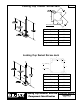
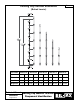
Rev. Locking Cup Tubular Screw Jack BOTTOM PLATE Part Number 0032-609 Maximum Extension 17” Minimum Extension 2” Adjustment Range 15” Overall Height 24” Weight Galvanized 8 lbs. Locking Cup Swivel Screw Jack 7” 5 12 ” 3 4 ” 3 4 ” 7 ” (2 HOLES) ø 16 5 12 ” 7” ø 58 ” (2 HOLES) Part Number 0032-135 Maximum Extension 22” Minimum Extension 8” Adjustment Range 14” Overall Height 28” Weight Galvanized Locking Cup Modular Scaffold Component Identification 15 lbs.
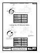
Locking Cup 8” Diameter Caster L WHEE ET OFFS Rev. 5-1/2” 4-1/2” 4-1/8” 2” 5” OVERALL HEIGHT CASTER WARNING LABEL PART NUMBER 0202-0146 Part Number 0026-001 Wheel Style Steel Wheel Offset 2” Overall Height 9-1/2” Wheel Thickness Weight 2” 15.4 lbs.
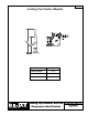
Rev. Locking Cup Caster Adapter Part Number 0254-13 Effective Height 13-1/4” Overall Height 19-5/32” Weight Galvanized 9.2 lbs.
Locking Cup Vertical Standards Rev. (Bolted Inserts) Part Number 0254-22-130 0254-22-125 0254-22-120 0254-22-115 0254-22-110 Units metric imperial metric imperial metric imperial metric imperial metric imperial Effective Ht. 3.0m 118-1/8” 2.5m 98-7/16” 2.0m 78-3/4” 1.5m 59-1/16” 1.0m 39-3/8” Overall Ht. 3.15m 124” 2.65m 104-9/32” 2.15m 84-19/32” 1.65m 64-15/16” 1.15m 45-1/4” Weight Galv. 17kg 37.5 lbs. 13.8kg 30.5 lbs. 11.6kg 25.5 lbs. 8.8kg 19.5 lbs. 6.1kg 13.5 lbs.
Rev. Locking Cup Vertical Standards (Without Inserts) Part Number 0254-19-130 0254-19-125 0254-19-120 0254-19-115 0254-19-110 Units metric imperial metric imperial metric imperial metric imperial metric imperial Effective Ht. 3.0m 118-1/8” 2.5m 98-7/16” 2.0m 78-3/4” 1.5m 59-1/16” 1.0m 39-3/8” Weight Galv. 17.3kg 38.1 lbs. 12.9kg 28.4 lbs. 10.9kg 24.1 lbs. 8.2kg 18.1 lbs. 5.5kg 12.1 lbs. Locking Cup Insert With Nut And Bolt Part Number 0007-186 Weight Galv. 2 lbs.
Rev. Locking Cup Horizontals Part Number 0254-02-2036 0254-02-2042 0254-02-2048 0254-02-2060 0254-02-2072 0254-02-2084 0254-02-2096 0254-02-2108 0254-02-2120 Technical Manual Section A Page of 21 Effective Length Net Length Overall Length Weight Galv. 3’ 3’ 6” 4’ 5’ 6’ 7’ 8’ 9’ 10’ 33-3/8” 39-3/8” 45-3/8” 57-3/8” 69-3/8” 81-3/8” 93-3/8” 105-3/8” 117-3/8” 34” 40” 46” 58” 70” 82” 94” 106” 118” 10 lbs. 11 lbs. 12 lbs. 14 lbs. 16 lbs. 18.6 lbs. 21.1 lbs. 24 lbs. 26.4 lbs.
Rev. Locking Cup Horizontal Trusses Part Number 0254-04-2084 0254-04-2096 0254-04-2120 0254-04-2144 Effective Length 7’ 8’ 10’ 12’ Net Length 81-3/8” 93-3/8” 117-3/8” 141-3/8” Truss Depth 13-25/32” 13-25/32” 13-25/32” 15-11/16” Overall Length 80-1/4” 92-1/4” 116-1/4” 140-1/4” Weight Galv. 32 lbs. 49 lbs. 60.3lbs. 73.9 lbs.
Rev.
Rev. Locking Cup Vertical Braces Part Number Post Spacing Tube Length Vertical Distance 0254-05-303620 3’ 88-7/32” 2.0m 78-3/4” 22 lbs. 0254-05-304220 3’ 6” 90-7/8” 2.0m 78-3/4” 22.5 lbs. 0254-05-304820 4’ 93-7/8” 2.0m 78-3/4” 23 lbs. 0254-05-306020 5’ 100-5/8” 2.0m 78-3/4” 24 lbs. 0254-05-307220 6’ 108-5/16” 2.0m 78-3/4” 25.5 lbs. 0254-05-308420 7’ 116-25/32” 2.0m 78-3/4” 26 lbs. 0254-05-309620 8’ 125-25/32” 2.0m 78-3/4” 27 lbs.
Rev. Locking Cup Vertical Braces Swivel Calmp Brace Part Number Post Spacing Tube Length 0254-24-303620 3’ 89-9/16” 2.0m 78-3/4” 23.5 lbs. 0254-24-306020 5’ 100-31/32” 2.0m 78-3/4” 27 ls. 0254-24-308420 7’ 117-1/8” 2.0m 78-3/4” 31.2 lbs. 0254-24-309620 8’ 126-5/32” 2.0m 78-3/4” 33.6 lbs. 0254-24-312020 10’ 145-17/32” 2.0m 78-3/4” 38.7 lbs. Technical Manual Section A Page 10 of 21 Vertical Distance Locking Cup Modular Scaffold Component Identification Weight Galv.
Locking Cup Solid Deck Adapter Part Number 0254-10 Overall Height 26-3/4” Weight Galv. 12 lbs. Locking Cup Modular Scaffold Component Identification Rev.
Rev. Locking Cup Side Bracket (One Board) Part Number 0254-07 Description One Board Effective Width 11-7/16” Net Width 9-3/4” Weight Galvanized 3.4 lbs. Locking Cup Side Brackets (Two and Three Board) CL CL Part Number 0254-08 0254-09 Description Two Board Three Board 22-1/4” 31-5/16” 18” 27” Overall Width 24-5/32” 33-3/16” Overall Height 18-27/32” 18-27/32” 10 lbs. 12.3 lbs.
Locking Cup Raised Steel Planks Rev. (Galvanized) Part Number Effective Length Overall Length Weight Galv. 0056-01-03 3’ 34” 16.6 lbs. 0056-01-04 4’ 51” 21.2 lbs. 0056-01-05 5’ 63” 25.9 lbs. 0056-01-06 6’ 75” 30.6 lbs. 0056-01-07 7’ 87” 35.2 lbs. 0056-01-08 8’ 99” 39.8 lbs. 0056-01-09 9’ 111” 44.6 lbs. 0056-01-10 10’ 123” 49.2 lbs.
Rev. Locking Cup Flush Steel Planks (Galvanized) Part Number Effective Length Overall Length Weight Galv. 0056-07-03 3’ 38-5/16” 18 lbs. 0056-07-04 4’ 50-5/16” 24 lbs. 0056-07-05 5’ 62-5/16” 28 lbs. 0056-07-06 6’ 74-5/16” 32 lbs. 0056-07-07 7’ 86-5/16” 36 lbs. 0056-07-08 8’ 98-5/16” 40 lbs. 0056-07-09 9’ 110-5/16” 44 lbs. 0056-07-10 10’ 120-5/16” 48 lbs.
Rev. Locking Cup Stair Stringers For Use With Raised Planks Part Number Side Bay Size Overall Length No. of Steps Weight Galv. 0042-229L Left 7’ x 2.0m 117-1/32” 8 60 lbs. 0042-229R Right 7’ x 2.0m 117-1/32” 8 60 lbs. 0042-171L Left 8’ x 2.0m 126-1/16” 10 70 lbs. 0042-171R Right 8’ x 2.0m NOTE: 2.0m = 6’ 6” (approximate) 126-1/16” 10 70 lbs. Locking Cup Stair Stringers For Use With Flush Planks Part Number Side Bay Size Overall Length No. of Steps Weight Galv.
Locking Cup Access Ladder Units Part Number 0004-0582 Part Number 0004-0581 Weight Galv. 18 lbs. Weight Galv. 9.5 lbs. Locking Cup Access Ladder Bracket Technical Manual Section A Page 16 of 21 Part Number 0063-0570 Weight Galv. 5.5 lbs. Locking Cup Modular Scaffold Component Identification Rev.
Rev. Locking Cup Base Beam (Boiler Applications) Part Number 0259-04-06BK Weight Galv. 115 lbs. Locking Cup Adjustable Support Bracket (Boiler Applications) 12 14 ” 1’ 7” 1’ 9” 10” 1’ 10 12 ” MIN. TO 2’ 4” MAX. 7” Part Number 0259-05BK Weight Galv. 53 lbs.
Locking Cup Support Frames (Boiler Applications) Part Number Effective Length Overall Length Weight 0259-03-01BK 12-1/8” 18-1/8” 12.2 lbs. 0259-03-03BK 36” 42” 26.2 lbs. 0259-03-05BK 60” 66” 37.8 lbs. 0259-03-06BK 72” 78” 43.5 lbs. Locking Cup Support Frame Starter (Boiler Applications) 10-1/4” Part Number 0259-02BK Weight Galv. 7.4 lbs. 13-3/16” Technical Manual Section A Page 18 of 21 Locking Cup Modular Scaffold Component Identification Rev.
Locking Cup Throat Header Rev. (Boiler Applications) NOTE: Ends of throat header are o tapered to fit 55 sloped boiler walls at base. Part Number 0077-253 Weight Galv. 52 lbs.
Rev. Locking Cup Saddle Brace (Boiler Applications) Part Number 0259-01BK Weight Galv. 21 lbs.
Rev. Locking Cup Storage Rack (Painted) 34” 44” Part Number 0110-209 Weight Galv. 120 lbs. 44” 5” Locking Cup Storage Rack Bin (Painted) Part Number 0110-211 Weight Galv. 125 lbs.
This Page Intentionally Left Blank
SECTION B Allowable Component Loads
SECTION B Introduction Allowable Component Loads This section contains illustrations and load ratings for the various systems scaffold components. The load ratings are based on the capacity of the individual components only. Refer to Section D and warning on inside front cover before computing the scaffold loads. Allowable loads specified in this section include safety factors required by Federal OSHA.
Capacity of Locking Cup Tubular Screw Jack Rev. (For Variable Jack Extensions) Jack Extension (X) Metric (m) Imperial (in.) Part Number 0032-609 Weight Galv. 7 lbs. Maximum Allowable Compressive Load (P) Metric (kn) Imperial (lbs.) 0.43m 17” 18kn 4,000 lbs. 0.35m 14” 31kn 7,000 lbs. 0.30m 12” 33kn 7,500 lbs.
Capacity of Locking Cup Swivel Screw Jack Part Number 0032-135 Weight Galv. 30 lbs. Max. Cap. 3000 lbs. at 22“ ANCHOR HOLE SIZE AND LOCATIONS ARE NOTED ON PAGE 1 OF SECTION A Capacity of Locking Cup Casters Part No. Wheel Dia. Wheel Style Allowable Rolling Load 0026-001 8” Steel 500 lbs. 0026-079 12” Steel 900 lbs. Rated For Scaffold Use Technical Manual Section B Page of 7 Rev.
Capacity of Locking Cup Vertical Standards Lift Height Metric (m) 2.0m Rev. Maximum Allowable Compressive Load Imperial (in.) Metric (kN) Imperial (lbs.) 78-3/4” 20kn 4,500 lbs.
Rev. Capacity of Locking Cup Horizontals Part Number Vertical Post Spacing Allowable Center Load 0254-02-2036 3’ 1,380 lbs. Allowable Uniform Load 920 lbs. / ft. 0254-02-2042 3’ 6” 1,180 lbs. 675 lbs. / ft. 0254-02-2048 4’ 1,040 lbs. 520 lbs. / ft. 0254-02-2060 5’ 830 lbs. 330 lbs. / ft. 0254-02-2084 7’ 595 lbs. 170 lbs. / ft.
Capacity of Locking Cup Horizontal Trusses Rev. Part Number Vertical Post Spacing Allowable Center Load Allowable Uniform Load 0254-04-2084 7’ 3,000 lbs. 860 lbs. / ft. 0254-04-2096 8’ 3,040 lbs. 760 lbs. / ft. 0254-04-2108 9’ 2,925 lbs. 650 lbs. / ft. 0254-04-2120 10’ 2,625 lbs. 525 lbs. / ft. 0254-04-2144 12‘ 2,400 lbs. 400 lbs. / ft.
Capacity of Locking Cup Side Brackets 250 lbs. for One Board Bracket 1000 lbs. for Two and Three Board Bracket Technical Manual Section B Page of 7 Locking Cup Modular Scaffold Component Allowable Loads Rev.
Rev. Capacity of Locking Cup Steel Planks Concentrated Load Uniform Load Part Number Effective Length 0056-01-03 3’ 0” 0056-01-04 4’ 0” Allowable Cen- Allowable Uniform Distributed ter Load Load Perforated Plank (lbs.) Perforated Plank (lbs. / lin. ft.) 770 472 Perforated Plank (lbs. / sq. ft.
This Page Intentionally Left Blank
SECTION C Assembly Details
SECTION C Introduction to Assembly Details This chapter contains illustrations of partially assembled scaffold components. The illustrations are provided as information to describe component fit and dimensional limitations. This chapter is not intended to be used as a guide for scaffold erection procedures.
Rev.
Rev.
Rev.
Rev.
Rev.
Rev.
Steel Plank and Filler Chart Horizontals Rev.
Steel Plank and Filler Chart Horizontal Trusses 9-1/2” Wide Flush Plank Technical Manual Section C Page of 10 Locking Cup Modular Scaffold Component Identification Rev.
Steel Plank and Filler Chart Horizontals Rev.
Steel Plank and Filler Chart Horizontal Trusses 9” Wide Raised Plank Technical Manual Section C Page 10 of 10 Locking Cup Modular Scaffold Component Identification Rev.
SECTION D Tieing and Bracing
SECTION D Tieing and Bracing Quantities and location of ties, guys and bracing will vary depending upon the scaffold size, weight, shape and load conditions. The following general guidelines indicate minimum bil-jax requirements and are not all inclusive. When designing scaffolds with unique configurations or special loading conditions, consult with bil-jax engineering or a professional structural engineer prior to design finalization.
Rev. Scaffolding Bracing Pattern Formula for Wall Tie Location Horizontal Distance = 28 ft. to 30 ft. Vertical Distance = 4 times the smaller distance of your bay layout Ex. A Scaffold setup that is 5 ft. wide by 52 ft. long by 100 ft. tall would require the following amount of wall ties: Horizontal - 100 divided by 28 = 3.5 (round up to 4) Vertical - 4 x 5 = 20 Conclusion - You will need 4 wall ties horizontally every 20 ft.
This Page Intentionally Left Blank
125 Taylor Parkway • Archbold, OH 43502 • www.biljax.