PARTS AND SERVICE MANUAL 36XT BOOM TM AERIAL WORK PLATFORMS
SELF-PROPELLED AERIAL WORK PLATFORM This equipment is designed and manufactured in compliance with the duties, responsibilities and standards set forth in the ANSI, CE, CSA and/or AS standards in effect at the time of manufacture. This equipment will meet or exceed applicable ANSI, CE, CSA and/or AS codes and standards when operated in accordance with manufacturer’s recommendations.
TABLE OF CONTENTS Table of Contents 1 Illustrations 2 Tables 2 1 Safety 3 Legend: Safety Advisories Before Operation During Operation Maintenance Safety Damaged Equipment Policy 4 5 5 7 8 2 Specifications 9 Range of Motion Specifications Warranty 10 11 12 3 Equipment Maintenance Daily Service Checks Weekly Service Checks Monthly Service Checks Annual Service Checks Structural Inspection Additional Service Information Troubleshooting Error Code Definitions 4 Cylinder Replacement Lift Cylinder
LIST OF ILLUSTRATIONS Figure 2-1 Range of Motion 10 Figure 3-1 Outrigger Position Switch 14 Figure 3-2 Hydraulic Reservoir 15 Figure 3-3 Wheel Nut Tightening Sequence 17 Figure 3-4 Slew Ring Position Measurement 18 Figure 4-1 Lift Cylinder Replacement 26 Figure 4-2 Outrigger Cylinder Replacement 27 Figure 5-1 Decal Locations 31 Figure 5-2 Decal Locations – CE 33 LIST OF TABLES 2 Table 1-1 Minimum Safe Approach Distances 5 Table 3-2 Troubleshooting Steps 20 Table 3-3 Error
1 SAFETY Proper training is required for the safe operation of any mechanical device. Failure to follow all instructions and safety precautions in this manual and attached to the lift will result in death or personal injury. Prior to Operation: Read, understand and obey all instructions and safety precautions in this manual and attached to the lift. Read, understand and obey all applicable government regulations. Become familiar with the proper use of all controls.
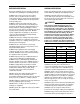
BIL-JAX 36XT LEGEND: SAFETY ADVISORIES The following safety advisories are used throughout this manual to indicate specific hazards when operating or maintaining the machine. Read, understand and obey all safety advisories to prevent improper service, damage to equipment, personal injury or death. DANGER Warns of operation near electrical power sources that could lead to personal injury or death. WARNING Describes conditions or practices that could lead to personal injury or death.
1 — SAFETY BEFORE OPERATION DURING OPERATION Ensure the following general safety precautions are followed before operating the articulating boom lift: Ensure the following general safety precautions are followed while operating the articulating boom lift: ALWAYS inspect the usage area for potential hazards, such as unstable or unlevel surfaces, overhead obstructions and electrically charged wires or conductors. ALWAYS watch for moving vehicles in the operating area.
BIL-JAX 36XT ALWAYS cordon the area surrounding the outriggers to keep personnel, vehicles and moving equipment away from the machine while in use. NEVER allow ropes, electric cords, hoses or other equipment to become entangled in the machine while raising or lowering platform. ALWAYS stay clear of overhead obstructions, including wires and cables. NEVER exceed the load limits set by the manufacturer.
1 — SAFETY MAINTENANCE SAFETY Ensure the following general safety precautions are followed while performing maintenance on the articulating boom lift: General Maintenance ALWAYS perform maintenance procedures according to manufacturer’s guidelines. NEVER disregard or bypass proper maintenance procedures. ALWAYS inspect hydraulic system to ensure that all lines, connectors and fittings are properly fastened and in good condition. ALWAYS turn the key switch OFF and remove key before performing maintenance.
BIL-JAX 36XT DAMAGED EQUIPMENT POLICY Safety Statement At Bil-Jax, we are dedicated to the safety of all users of our products. All Bil-Jax lifts are designed, manufactured and tested to comply with current applicable federal OSHA and ANSI codes and regulations. Damage Policy There may be occasions when a Bil-Jax lift is involved in an incident that results in structural damage to the lift. Such damage can seriously compromise the ability of the lift to perform in a safe manner.
2 SPECIFICATIONS Bil-Jax, Inc. is dedicated to the continuous improvement of this and all Bil-Jax products. Therefore, equipment information is subject to change without notice. The following information is based on ideal working conditions. Machine performance may vary based on work environment and on machine options. Direct any questions or concerns regarding equipment specifications to your regional Bil-Jax representative or to the Bil-Jax Service Department.
BIL-JAX 36XT RANGE OF MOTION Figure 2-1.
2 — SPECIFICATIONS SPECIFICATIONS Working Height Maximum Platform Height Maximum Horizontal Outreach From Centerline From Outrigger Footpad Edge Rated Platform Capacity Without Platform Rotation With Platform Rotation Maximum Occupants Total Weight SERIAL NUMBER____________________________ 43 ft 6 in 13.4 m 37 ft 6 in 11.4 m 32 ft 9.8 m 27 ft 8.2 m 500 lbs 227 kg 440 lbs 200 kg 2 4,680 lbs 2,123 kg Turntable Rotation 700º Non-Continuous Leveling Capability 12.
BIL-JAX 36XT WARRANTY Bil-Jax, Inc. warrants this product for one year, beginning on the date of delivery, to be free from defects of material and workmanship provided the unit is operated and maintained in compliance with the guidelines established in the Operations and Maintenance Manuals. Major structural components, including trailer tongue and boom weldments, are warranted for five years against defects due to material or workmanship.
3 EQUIPMENT MAINTENANCE Performing the appropriate maintenance procedures will extend the life of the boom lift and will help ensure the safety of personnel operating the equipment. Repair, replacement or adjustment of any hydraulic or electrical control device should be performed only by fully trained and authorized personnel. These include, but are not limited to, hydraulic load valves, hydraulic flow control valves, solenoid valves and limit switches. These are safety related controls.
BIL-JAX 36XT DAILY SERVICE CHECKS The following maintenance procedures should be performed daily or before each operation. Verify that all decals are correctly applied and in plain view. Refer to Section 5 for decal locations. Verify that all controls and indicators at ground and platform control stations operate properly. Lower outriggers to level the boom lift. Raise and extend all booms. Press emergency STOP button. Verify that boom down limit switches operate correctly.
3 — EQUIPMENT MAINTENANCE Inspect hydraulic system and fluid levels. Check all hydraulic hoses and fittings for leaks and damage. Tighten or replace as necessary to prevent hydraulic oil or pressure loss. The hydraulic oil level should be checked with the booms down, all outriggers raised and the trailer wheels on a level surface. Hydraulic oil level should be visible in, but not above, the sight gauge.
BIL-JAX 36XT WEEKLY SERVICE CHECKS Perform the following service checks at least once each week in addition to all recommended Daily Service Checks: Check Battery electrolyte level. If electrolyte level is low, add enough water to bring the electrolyte level to the top of the plates. If batteries are fully charged, raise electrolyte level to full mark in each cell. Inspect all electrical wiring. Check for cuts, loose terminals, broken wires, chaffing and corrosion.
3 — EQUIPMENT MAINTENANCE MONTHLY SERVICE CHECKS Perform the following service checks at least once each month: Clean all battery terminals. Check battery for loose connections or damaged wires. Verify proper operation of manual lowering valves and hand pump Refer to Section 3 for manual boom operating procedures. Lubricate all compartment hinges and latches, slew ring and mating gear. Use NLGI Grade 2 multi-purpose grease. Check wheel nut torque.
BIL-JAX 36XT ANNUAL SERVICE CHECKS Perform the following service checks at least once each year: Replace Hydraulic Oil and Oil Filter. Drain hydraulic reservoir, clean and replace oil. Wipe away dirt and excess oil from around filter using cleaning cloths and alcohol solvent. Loosen and remove filter. Use absorbent cloths to keep excess oil from leaking onto the machine. Discard used filter. Wipe away dirt and excess oil from around filter housing. Install new filter. Do not over-tighten.
3 — EQUIPMENT MAINTENANCE STRUCTURAL INSPECTION ADDITIONAL SERVICE INFORMATION A comprehensive structural inspection of the unit shall be performed under any of the following conditions. Seals on hydraulic cylinders should be replaced every five years or as indicated by machine performance. Ten years from the date of manufacture and every five years thereafter. After any actual, suspected or potential damage is sustained that could affect the structural integrity or stability of the aerial platform.
BIL-JAX 36XT TROUBLESHOOTING Refer to Table 3-2 for basic troubleshooting operations. Additional information can be found in the Bil-Jax Model 45XA Operator’s Manual. Contact the Bil-Jax Service Department with any questions or before attempting any advanced troubleshooting operations. Table 3-1. Troubleshooting Steps PROBLEM No lights on panel when key switch is turned to the on position. CAUSE SOLUTION a. Emergency STOP engaged. a. Disengage Emergency STOP buttons. b. Battery charge is low. b.
3 — EQUIPMENT MAINTENANCE ERROR CODE DEFINITIONS The DISPLAY PANEL located on the ground control panel indicates the present operating status of the boom lift. If an error condition is detected by the control processor during start-up or operation, the appropriate error code will be displayed on this panel. Refer to Table 3-2 for a comprehensive list of Error Code Definitions and solutions. Table 3-2.
BIL-JAX 36XT ERROR MESSAGE DEFINITION OF ERROR COMMENTS 031 OPEN CIRCUIT JIB DOWN A load of less than 70mA detected when jib down circuit was energized Check for faulty jib down solenoid coil and wiring. 032 SHORTED CIRCUIT JIB DOWN Excessive load detected when jib down circuit was energized. Check for faulty jib down solenoid coil and wiring. 033 OPEN CIRCUIT EXTEND A load of less than 70mA detected in extend circuit on power-up. Check for faulty boom extend solenoid coil/wiring.
3 — EQUIPMENT MAINTENANCE ERROR MESSAGE DEFINITION OF ERROR COMMENTS 056 SHORTED CIRCUIT RF OUTRIGGER Excessive load detected in right front outrigger circuit on power-up. Check for faulty solenoid coil/wiring at outrigger. 057 OPEN CIRCUIT LR OUTRIGGER A load of less than 70mA detected in left rear outrigger circuit on power-up. Check for faulty solenoid coil/wiring at outrigger. 058 SHORTED CIRCUIT LR OUTRIGGER Excessive load detected in left rear outrigger circuit on power-up.
BIL-JAX 36XT 24
4 CYLINDER REPLACEMENT If repair or replacement of a boom lift or outrigger hydraulic cylinder or its component parts becomes necessary, observe the following procedures in accordance with the safety precautions established in Section 1 of this manual. Removing the hydraulic cylinder from the boom lift may require the use of specialized tools and lifting equipment. NEVER attempt to operate overhead hoists or cranes or related equipment without proper training, authorization and supervision.
BIL-JAX 36XT LIFT CYLINDER REPLACEMENT Use the following procedure to remove and replace faulty or damaged hydraulic cylinders on the boom lift: WARNING Repair and removal of the hydraulic cylinders requires the use of lifting straps and an overhead crane or lifting gear to support the boom lift and hydraulic cylinders. Personnel should be thoroughly trained in the operation of these devices before attempting installation or removal.
4 — CYLINDER REPLACEMENT OUTRIGGER CYLINDER REPLACEMENT Use the following procedure to remove and replace faulty or damaged hydraulic cylinders on the outriggers: Lower the outrigger until the footpad is touching the ground. Do not transfer the weight of the boom lift onto the outrigger. Leave the weight of the boom on the trailer wheels. Unplug the cylinder valve solenoid. Place absorbent cloths below the cylinder ports and detach hydraulic hoses from the cylinder. Elevate hoses to prevent leakage.
BIL-JAX 36XT 28
5 REPLACEMENT DECALS Decals contain information that is required for the safe and proper use of the aerial work platform. Decals should be considered necessary components of the machine and should be checked before each use to verify that they are correctly attached and legible. Use the following guides to find the correct location of all decals.
BIL-JAX 36XT Table 5-1. Decal Descriptions Decal No. Decal Description Qty Decal No.
0476 0474 0471 0562 0552 0062 0475 0202-0523 0473 0405 0552 0521 0552 0481 0405 0493 0034 0484 0495 0161B 0405 0552 0563 0505 4x 0561 0404 0521 0495 0545 0477 0476 0506 0405 0504 0503 0541 0494 0068 0037 0482 5 – DECAL PLACEMENT Figure 5-1.
BIL-JAX 36XT Table 5-2. Decal Descriptions – CE Decal No. Decal Description Qty Decal No.
0476 0471 0474 0562 0173 0202-0523 0062 0475 0405 0552 0405 0034 0475 0476 0495 0161B 0405 0568 0405 0552 0505 0563 4x 0561 0572 0404 0034 0495 0545 0506 0405 0541 0068 0037 0482 5 — REPLACEMENT DECALS Figure 5-2.
BIL-JAX 36XT 34
6 MATERIAL SAFETY DATA The following Material Safety Data Sheets describe the correct procedures for the safe handling of chemical components within the Model 45XA Articulating Boom Lift, as well as any potential health and safety hazards related to these chemicals. Material Safety Data Sheets are included here in accordance with applicable federal and state regulations. Read and observe all safety precautions. Maintain awareness of potential health and safety hazards.
BIL-JAX 36XT MATERIAL SAFETY DATA SHEET FOR LEAD ACID BATTERIES, WET, FILLED WITH ACID (Continued) SECTION V -- HEALTH HAZARD DATA Primary Routes of Entry: Inhalation: YES Skin: YES Ingestion: YES Acute EYES, SKIN, RESPIRATORY SYSTEM & DIGESTIVE SYSTEM Chronic: EYES, SKIN, RESPIRATORY SYSTEM & DIGESTIVE SYSTEM IRRITATION OF EXPOSED AREA, BURNS AND RESPIRATORY PROBLEMS NO POSSIBILITY OF EXPOSURE OF LEAD WILL OCCUR UNLESS BATTERY IS DESTROYED.
6 – MATERIAL SAFETY DATA MATERIAL SAFETY DATA SHEET DEXRON III/MERCON AUTOMATIC TRANSMISSION FLUID (HYDRAULIC OIL) SECTION I -- GENERAL INFORMATION TRADE NAME: EMERGENCY TELEPHONE NUMBERS: CHEMICAL FAMILY: CAS NUMBER: MIXTURE. HAZARDOUS INGREDIENTS: CITGO TRANSGARD™ ATF, DEXRON III/MERCON 918.495.4700 (medical); 800.424.9300 (chemical) AUTOMATIC TRANSMISSION FLUID, LUBRICATING OIL REVISION DATE: 10/29/98 CONTAINS NO INGREDIENTS NOW KNOWN TO BE HAZARDOUS AS DEFINED IN OSHA 29 CFR 1910.
38
APPENDIX:REPLACEMENT PARTS Use only parts manufactured and/or authorized by Bil-Jax, Inc. when replacing damaged components. See page 89 for replacement part ordering information. Only personnel properly trained and authorized to operate all equipment and familiar with all boom functions should attempt to repair or replace any part of the boom lift.
Assembly Description 40 Page Outrigger 42 Engine 44 Front Rest 48 Front Axle 50 Rear Axle 52 Slew Ring 54 Counterweight 56 Control Compartment 58 Pump Compartment 60 Battery Compartment 62 Cover 64 Boom 66 Cable Track 70 Boom Nose 72 Platform 74 Hydraulic Pump 76
Assembly Description Page Boom and Rotation Hydraulic Lines 80 Outrigger Hydraulic Lines 82 Trailer Hydraulic Lines – 4WD 83 Wire Harnesses 86 Manifold Wire Harness 87 Gas Engine Wire Harness 87 Choke/Throttle Solenoid Wire Harness 88 Engine Relays Wire Harness 88 ATC Fuse Holder 89 Start/Stop/Run Wire Harness 89 Generator Switcher Box 90 Wire Assembly – Fan 90 IEC Cord – Male – US Markets 91 Generator 110V Wire Harness 91 Oil Switch 91 Cord Assembly – 110V Generator 92 Cor
OUTRIGGER ASSEMBLY 28 18 21 15 16 17 11 10 14 12 13 9 4 5 13 30 6 14 7 29 14 26 27 2 23 6 5 24 7 25 4 22 42 20 19 17 6 5 7 8 1 3
OUTRIGGER ASSEMBLY PARTS LIST Item No. Part No. Description Qty. 1 A-00120 Outrigger Weldment 1* 2 A-00046 Grommet – 1.5 x 1.25 x 1.75 1 3 A-00032 Bearing 2 4 A-00020 Pin, 1.25 x 5.5 2 5 A-00019 Pin Retainer, 1.25 3 6 0096-0016 Cap Screw, M10 x 25 3 7 0096-0041 Hex Nut, Self-Locking, M10 3 8 A-00060 Pin, 1.25 x 4.
ENGINE ASSEMBLY (I) 5 6 25 12 24 4 21 2 16 17 3 11 10 19 8 7 8 15 8 8 9 20 22 14 7 15 13 2 2 44 1 3 23 3 15 18
ENGINE ASSEMBLY (I) PARTS LIST Item No. Part No. Description Qty.
ENGINE ASSEMBLY (II) 3 21 12 17 15 14 12 12 3 6 7 1 2 4 5 18 9 10 12 22 13 20 16 13 11 19 3 25 24 26 27 23 33 31 32 34 28 46 29
ENGINE ASSEMBLY (II) PARTS LIST Item No. Part No. Description Qty. 1 A-01046 Engine 21HP (See Manufacturer’s Literature) 1 2 0096-0098 Cap Screw, M8 x 35 4 3 0096-0040 Hex Nut, Self-Locking, M8 18 4 A-01048 Pump – Dual – 4.
FRONT REST ASSEMBLY 12 9 14 13 19 17 16 15 11 18 5 6 10 6 21 4 8 2 7 1 21 3 22 48 20 20
FRONT REST ASSEMBLY PARTS LIST Item No. Part No. Description Qty.
FRONT AXLE ASSEMBLY 8 18 14 15 19 17 22 8 23 24 20 12 21 16 13 7 3 6 5 13 4 9 10 1 50 11 2
FRONT AXLE ASSEMBLY PARTS LIST Item No. Part No. Description Qty. 1 A-01010 Front Axle Weldment – 4WD 1 2 A-01097 Bushing, 1.5” OD x 1.25” ID 4 3 A-01020 Front Yoke – Left 1 4 A-01021 Front Yoke – Right 1 5 A-01070 Pin – 1.25” x 1.625” 4 6 A-00019 Pin Retainer – 1.
REAR AXLE ASSEMBLY 2 7 1 52 2 6 4 5
REAR AXLE ASSEMBLY PARTS LIST Item No. Part No. Description Qty.
SLEW RING ASSEMBLY 13 12 11 9 1 3 6 2 5 7 4 8 10 54
SLEW RING ASSEMBLY PARTS LIST Item No. 1 Part No. A-02189 Description Slew Assembly and Adapter Qty.
COUNTERWEIGHT ASSEMBLY 56
COUNTERWEIGHT ASSEMBLY PARTS LIST Item No. Part No. Description Qty.
CONTROL COMPARTMENT ASSEMBLY 8 10 21 22 21 8 13 12 15 7 6 13 14 7 1 7 9 4 2 58 3 8 7 8 5 8 11 16 17 18 19 20 7
CONTROL COMPARTMENT ASSEMBLY PARTS LIST Item No. Part No. Description Qty.
PUMP COMPARTMENT ASSEMBLY 4 2 3 6 5 4 1 7 60
PUMP COMPARTMENT PARTS LIST Item No. Part No. Description Qty.
BATTERY COMPARTMENT ASSEMBLY 16 10 16 15 17 3 30 22 17 24 16 20 23 18 21 19 25 26 27 29 8 6 7 28 4 14 11 8 62 12 9 13 1 2 5
BATTERY COMPARTMENT ASSEMBLY PARTS LIST Item No. Part No. Description Qty.
COVER ASSEMBLY 5 3 4 6 7 7 8 9 10 64 1 2
COVER ASSEMBLY PARTS LIST Item No. Part No. Description Qty.
BOOM ASSEMBLY (I) 10 6 3 4 8 9 4 5 2 3 4 5 66 9 4 7 1 8 9
BOOM ASSEMBLY PARTS LIST Item No. Part No. Description Qty. 1 A-00552 Hydraulic Master Cylinder 1 2 A-00024 Pin, .75 x 8.5 1 3 A-00017 Pin Retainer – .75 2 4 0096-0016 Cap Screw, M10 x 25 7 5 0096-0041 Hex Nut, Self-Locking, M10 7 6 A-00026 Pin, .75 x 7.0 1 7 A-00551 Hydraulic Boom Cylinder 1 8 A-00021 Pin, 1.25 x 8.5 2 9 A-00019 Pin Retainer – 1.25 5 10 A-00023 Pin, 1.25 x 7.
BOOM ASSEMBLY (II) 7 3 5 1 11 13 14 2 6 8 5 10 9 28 4 25 27 26 24 14 21 13 12 68 17 15 16 24 18 23 19 20 22
BOOM ASSEMBLY PARTS LIST Item No. Part No. Description Qty. 1 A-00510 Telescopic Boom Tube 1 2 A-00550 Hydraulic Extension Cylinder 1 3 A-00535 Slider 2 4 0096-0018 Cap Screw, M10 x 40 4 5 0096-0041 Hex Nut, Self-Locking, M10 6 A-00032 Bearing 2 7 0096-0033 Flat Head Cap Screw, M16 x 35 4 8 A-00027 Pin, .75 x 7.0 1 9 A-00017 Retainer – .
CABLE TRACK ASSEMBLY 4 5 6 7 8 3 2 2 3 3 8 12 2 13 1 70 11 10 9 3 14
CABLE TRACK ASSEMBLY PARTS LIST Item No. Part No. Description Qty.
BOOM NOSE ASSEMBLY 31 1 8 21 13 22 2 15 28 29 16 30 17 18 3 23 4 13 5 2 24 27 25 26 72 12 7 8 10 11 9 19 6 20 14
BOOM NOSE ASSEMBLY PARTS LIST Item No. Part No. Description Qty. 1 A-00979 Bulkhead Mount 1 2 0096-0016 Cap Screw, M10 x 25 4 3 A-00601 Platform Pivot Weldment 1 4 A-00025 Pin, 1.0 x 6.5 1 5 A-00018 Pin Retainer – 1.
PLATFORM ASSEMBLY 17 16 13 15 14 22 23 24 7 5 6 18 7 9 11 12 21 2 1 20 19 13 74 10
PLATFORM ASSEMBLY PARTS LIST Item No. Part No. Description Qty.
76 20 4 19 17 17 17 23 2 21 15 20 5 21 19 14 11 19 17 16 17 10 20 13 17 1 8 9 24 17 19 3 17 18 25 6 24 12 22 19 17 7 PUMP ASSEMBLY (A-00254)
PUMP ASSEMBLY PARTS LIST Item No. Part No. Description Qty.
78 3 17 5 15 18 4 22 6 20 15 19 2 13 12 14 9 8 10 7 16 11 1 21 PUMP ASSEMBLY, CONTINUED
PUMP ASSEMBLY PARTS LIST, CONTINUED Item No. Part No. Description Qty. 1 B02-15-0513 Reservoir 1 2 B02-15-0470 Pump Assembly, 2.09 CCM 1 3 B02-15-0471 Motor, Pump, 24 VDC 1 4 B02-15-0500 Coupling, .875 x 2.795 1 5 B02-15-0501 Filter, Hydraulic 1 6 B02-15-0476 Sight Glass 1 7 B02-15-0477 Socket Head Cap Screw, M8 x 85 2 8 B02-02-0247 Fitting, Plug, M14 x 1.5 x 5.
BOOM AND ROTATION HYDRAULIC LINES (A-00269) 80
BOOM AND ROTATION HYDRAULIC LINES PARTS LISTS Item No. Part No.
OUTRIGGER HYDRAULIC LINES (A-03182) 1 RET 6 4 2 8 1 7 9 EXT 5 10 2 1 2 9 3 1 R ET EX T 2 EX T T RE R ET T EX 10 10 RE 10 EX T T OUTRIGGER HYDRAULIC LINES PARTS LIST 82 Item No. Part No. Description Qty.
1A 1 2A 2 A 7 A (2) #8MORFS-#10MORB 45 FF6802-8-10 6 #10MORFS-#10MOBR-#10MORFS Tee FF6804-10-10-10 #10MORFS-#10FMORFS 90 FF6500-10-10 #12ORBM-#10ORBFM STR 6410-12-10 OIL COOLER Dual Pump 5GPM 6 5 1B Banjo Bolt 10MORB Plug 6408-H-10 3 4B #8MORFS Tee FF2603-8-8-8 Driver ORB 2B #4MORFS-#4MORB 90 FF6801-4-4 3B #10MORFS-#12ORB 90 FF6801-10-12 7 #8MORFS-#12MORB STR FF6400-8-12 3A 4 SMB SMA #6MORFS-#6MORB STR FF6400-6-6 8 #4MORFS-#4MORB 90 FF6801-4-4 13 TP3 12 P1A 90 9 FF680
TRAILER HYDRAULIC LINES PARTS LISTS Item No. 84 Part No.
FITTINGS Part No. Description Qty.
WIRE HARNESSES Upper Control Box Platform Plug B F D E Motor Cntl B+ Motor Cntl B- A Wh Bla Blu 2 Re Or 3 1 C Gr 6 4 8 7 9 J4 Platform Connector P4 & P5 Connector P3 Turntable Connector 36 P1 Analog Connector 24 12 1 23 16 8 1 P2 Lift/Engine Connector 35 24 12 1 11 24 3 1 4 2 26 15 27 13 16 23 14 8 22 22 15 1 23 20 5 12 1 31 3 21 13 7 20 8 23 10 14 9 17 35 34 18 32 32 16 + - X Y R O Br B + Jib Cyl C17 Strobe Prop Coil C8 Sec Cyl C16
MANIFOLD WIRE HARNESS (A-00785) Deutsch Term.
CHOKE /THROTTLE SOLENOID WIRE HARNESS (A-01042) 1" A-01042 Rev- Put Wires in 16" Split tubing Heat Seal Both ends Weather Pack FM Term 12089188 Cable Seal 12015323 FM Housing 12015792 B B A W Label 20" 18ga TXL Or Equivalent ENGINE RELAYS WIRE HARNESS (A-01044) A-01044 Rev- Solder inline & Heat Shrink Label 10" Split Tube Wrap Tape At Each End ¼” Female Spade Engine Run Red 8" 6" Y 88 3" 3" 3" R 4" FAN 4" Red Fuel F 87 15" Ign K 87a Black 15" ¼” Female Spade Starter S 87 Y
ATC FUSE HOLDER (A-01049) ATC Fuse Holder Waytek # 46278 or Equivalent 5/16" Ring Term ¼” Female Spade Ins 4"- 6" Leads 12 ga Wire 4"- 6" Leads 12 ga Wire START/STOP/RUN WIRE HARNESS (A-01098) 2" A-01098 Rev 10" 7" Label Split Tube Wrap & Heat Shrink Each End Wire Label Tape Both Sides of Drop Out 18" Delphi Weather Pack 12020832 4 Pin Female Conn 12089188 Female Term 12015323 Green Wire Seal Start S 86 Length A Red 24" B White 26" Blue 20" 8" GND 85 Green 20" 6" GND 85 4" GND
GENERATOR SWITCHER BOX ASSEMBLY (A-03040) Box-A-01015 B01-06-0056 30 Amp Relay DPST – NO Allied Electronics #850-0345 Or Equivilant B01-01-0180 B01-10-0354 20 Amp Circuit Breaker W/.
IEC CORD MALE – US MARKETS (A-03042) 18" A-03042 Rev SO cable or Equivalent Label North America 120V Male Plug Minimum Requirements IEC 90 Degree Plug Interpower IEC 60320 C19 Mold 012 Current 15 AMP Voltage 120/240VAC GENERATOR 110V WIRE HARNESS (A-03043) A B B W C G 12-3 SO Or Equivilant 36" (+/- 2") .
CORD ASSEMBLY 110V GENERATOR (B01-01-0178) 14-3 SO or Equivalent Delphi Weather Pack 12015793 3 Pin Female Housing 12124580 Female Terminal 12/14ga 12010293 Seal 12/14ga B C B01-01-0178 Rev ¼” Female Spade W B W G B ¼” Female Spade G 24" A #10 Ring Terminal 4" Label CORD ASSEMBLY GENERATOR SWITCH (B01-01-0179) 28" A W B B ¼” Female Spade B01-01-0179 Rev ¼” Female Spade 18-2 SO or Equivalent Delphi Weather Pack 12010973 2 Pin Male Housing 12089040 Male Terminal 12015323 Green Seal 4" L
SWITCHER BOX ASSEMBLY – CE MODELS (A-03040CE) Box-A-01015 B01-01-0180 B01-10-0354 20 Amp Circuit Breaker W/.
PUMP AND CYLINDER WIRE HARNESS (A-00716) 94
OUTRIGGER SWITCH & COIL WIRE HARNESS (A-00746) 95
ANALOG HARNESS (A-00715) Amp 770680 Label Individual Wire Labels AMP 770520-1 A-00715 Rev 1" Amp Housing 770680-1 Black Pump Speed Signal Pin 1 3' (36") 18 ga Green Pin 16 3' (36") 18 ga Yellow Motor Cntrl Enab Ground Pin 9 12" 18 ga Black Engine Run + Pin 10 ¼” FM Spade Insulated ¼” FM Spade Insulated 15" Loom Weather Pack 12010973 2 Pin Housing 12089040 Male Terminal 12015323 Wire Seal B A 12" 18 ga Red 10" Loom Engine Run 1 16 18" 18ga Red ¼” FM Spade Insulated ¼” FM Spade Insul
PLATFORM-GROUND COMMUNICATION CABLE (A-00714) 97
MATERIAL LIFT HOOK ASSEMBLY (OPTION A-00846) 5 8 4 1 3 11 4 2 10 9 7 6 17 19 18 15 16 98 13 14 12
MATERIAL LIFT HOOK PARTS LIST Item No. Part No. Description Qty.
BATTERY LAYOUT - + - + 3 + 3 - + - 2 1 + - 10 + - 4 D4 Motor Controller 5 6 3 BD6 D1 0-5V Enable D5 1 M- B+ E2 A2 D2 D3 Contactor 24VDC 100AMP B01-06-0058 200 AMP Fuse D1 E1 Drive Motor Pump 200 AMP Fuse 8 9 B+ 1 11 M- B3 Enable 0-5V 7 E2 A2 D1 E1 Main Pump Motor Contactor 24VDC 100AMP B01-06-0058 Item No.
ORDERING REPLACEMENT PARTS To order replacement parts, contact the Bil-Jax Service Department by phone at 800-537-0540, by fax at 419-446-8202 or by email at techsupport@biljax.com. For swift service, always have the part number available, as well as the equipment model and serial number. When ordering parts by fax or email, always provide the above information. See Page 12 for Equipment Warranty information.
102
NOTES
Distributed by: 125 Taylor Parkway Archbold, OH 43502 Phone (419) 445-8915 (800) 537-0540 Fax (419) 445-0367 http://www.biljax.