
user manual

XLB-4232 DC
6-38
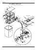
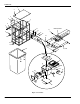
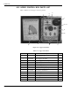
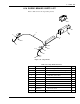
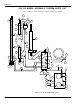
6-15 UPPER CONTROL BOX PARTS LIST
Refer to Table 6-15 for the upper control box parts list.
1
2
9
2
3
4
5, 6, 7
8
10
11
12
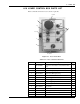
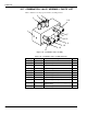
Figure 6-15. Upper Control Box
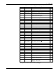
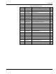
Table 6-15. Upper Control Box
Item No. Part No. Description Qty
B19-00-0010 Switch Panel Assembly, Upper Control Box
(includes items 1-11)
1
1 B19-00-0003 Panel, Upper Control Box 1
2 B01-02-0010 Switch, Toggle, Lift/Telescope/Rotate/Tilt 4
3 B01-10-0017 Gage, Battery 1
4 B01-02-0013 Switch, Toggle, Speed 1
5 B01-02-0031 Button, Emergency Stop 1
6 B01-02-0032 NC Contact, Emergency Stop 1
7 B01-10-0055 Block, NC Contact Mount 1
8 B01-02-0012 Switch, Toggle, Controls On/Off 1
9 B06-00-0117 Decal, Bucket Tilt 1
10 B06-00-0118 Decal, Upper Control Box 1
11 B06-00-0116 Decal, “OPERATE WITH FULLY…” 1
12 B06-00-0144 Decal, Specifications 1