BiPAC 7300VP/7300VGP VoIP/(802.
Chapter 1 ................................................................................................................... 2 1.1 Introducing the BiPAC 7300VGP series .............................................. 2 1.2 Features................................................................................................. 4 1.3 Applications of the BiPAC 7300VGP series........................................ 8 Chapter 2 .....................................................................................
Chapter 1 Introduction 1.1 Introducing the BiPAC 7300VGP series Thank you for purchasing the BiPAC 7300VGP series ADSL2+ Router by Billion. Your new router is an all-in-one unit that combines an ADSL modem, ADSL2/2+ router and Ethernet network switch to provide everything you need to get the machines on your network connected to the Internet over an ADSL broadband connection.
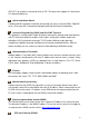
addresses making them invisible to outside users on the Internet, so it is much more difficult for a hacker to target a machine on your network. Second, it can block and redirect certain ports to limit the services that outside users can access. To ensure that games and other Internet applications run properly, you can open specific ports for outside users to access internal services on your network.
1.2 Features Express Internet Access – ADSL2/2+ capable The BiPAC 7300VGP series complies with ADSL worldwide standards. Supporting downstream rates of 8Mbps with ADSL, the router is capable of up to 12/24 Mbps with ADSL2/2+, and upstream rates of up to 1 Mbps. Users enjoy not only high-speed ADSL services but also broadband multimedia applications such as interactive gaming, video streaming and real-time audio which are easier and faster than ever. The router is compliant with Multi-Mode standard (ANSI T1.
(RFC1577) to establish a connection with an ISP. The router also supports VC-based and LLC-based multiplexing. Quick Installation Wizard A web-based GUI and quick installation wizard help you easily install the BiPAC 7300VGP series. Enter your ISP’s information and begin browsing the Internet immediately.
The BiPAC 7300VGP series provides an embedded PPPoE client function to establish a connection. You get greater access speed without changing the operation concept, while sharing the same ISP account and paying for one access account. No PPPoE client software is required for the local computer. Automatic Reconnect and Disconnect Timeout (Idle Timer) functions are also provided.
A web-based GUI offers easy configuration and management. User-friendly and with on-line help, it also supports remote management capability for remote users to configure and manage this product. Firmware Upgradeable You can upgrade the router with the latest firmware through its web-based GUI.
1.
Chapter 2 Product Overview Standards-Based Technology The BiPAC 7300VGP Wireless Router utilizes the 802.11g standard. The IEEE 802.11g standard is an extension of the 802.11b standard. It increases the data rate up to 54Mbps* within the 2.4GHz band, utilizing OFDM technology. This means that in most environments, within the specified range of this device, you will be able to transfer large files quickly or even watch a movie in MPEG format over your network without noticeable delays.
effect on range. Try to position wireless devices and computers with wireless adapters so that the signal passes through drywall or open doorways and not other materials.4 Keep your product away (at least 3-6 feet or 1-2 meters) from electrical devices or appliances that generate extreme RF noise. 2.1 Important Notes Do not use the BiPAC 7300VGP series in high humidity or high temperatures. Do not use the same power source for the BiPAC 7300VGP series as other equipment.
2.3 The Front LEDs LED Description 1 PWR: Lights when the power is ON. 2 SYS: Lights when the system is ready. 3-6 LAN Port 1-4: Steady glow when connected to an Ethernet device. Glows green for 100Mbps; Orange for 10Mbps. Blinking light when data is Transmitted / Received. 7 WLAN: (7300VGP only) Lit green when the wireless connection is established. Flashes when sending/receiving data. 8-9 Phone: Lit green when the phone is off-hook. 10 LINE: 11 VoIP: Lit when SIP registration is OK.
2.4 The Rear Ports 8 7 6 Port 5 4 3 1 Description 1 Power Switch Power ON/OFF switch. 2 PWR Connect the supplied power adapter to this jack. 3 2 RESET After the router is powered on, press this recessed button using the end of paper clip or other small pointed object to reset the router or to restore it to factory default settings. 1. Recovery procedures for non-working routers (e.g. after a failed firmware upgrade flash): 2.
The detail instruction in Emergency/Failure Recovery Button 1. Recovery procedures for non-working routers (e.g. after a failed firmware upgrade flash): Hold the Emergency/Failure Recovery Button on the back of the modem in. Keep this button held in and turn on the modem. Once the lights on the modem have stopped flashing, release the Emergency/Failure Recovery Button. The modem's emergency-reflash web interface will then be accessible via http://192.168.1.
2.5 Cabling One of the most common causes of problems is bad cabling or ADSL line(s). Make sure that all connected devices are turned on. On the front of the product is a bank of LEDs. Verify that the LAN Link and ADSL line LEDs are lit. If they are not, verify that you are using the proper cables. Ensure that all other devices connected to the same telephone line as your Billion router (e.g.
Chapter 3 Installation You can configure the BiPAC 7300VGP series router through the convenient and user-friendly interface of a web browser. Most popular operating systems such as Linux and Windows 98/NT/2000/XP/Me include a web browser as a standard application. 3.1 Before Configuration PCs must have a properly installed Ethernet interface and connect to the router directly or through an external repeater hub.
Configuring a PC in Windows XP 1. Go to Start / Control Panel (in Classic View). In the Control Panel, double-click on Network Connections 2. Double-click Local Area Connection. 3. In the Local Area Connection Status window, click Properties. 4. Select Internet Protocol (TCP/IP) and click Properties.
5. Select the Obtain an IP address automatically and the Obtain DNS server address automatically radio buttons. 6. Click OK to finish the configuration. Configuring a PC in Windows 2000 1. Go to Start / Settings / Control Panel. In the Control Panel, double-click on Network and Dial-up Connections. 2. Double-click Local Area Connection. 3. In the Local Area Connection Status window click Properties.
4. Select Internet Protocol (TCP/IP) and click Properties. 5. Select the Obtain an IP address automatically and the Obtain DNS server address automatically radio buttons. 6. Click OK to finish the configuration. Configuring PC in Windows 98/Me 1.Go to Start / Settings / Control Panel. In the Control Panel, double-click on Network and choose the Configuration tab. 2.Select TCP/IP ->NE2000 Compatible, or the name of your Network Interface Card (NIC) in your PC.
3.Select the Obtain an IP address automatically radio button. 4.Then select the DNS Configuration tab. 5.Select the Disable DNS radio button and click OK to finish the configuration. Configuring PC in Windows NT4.0 1.Go to Start / Settings / Control Panel. In the Control Panel, double-click on Network and choose the Protocols tab. 2.Select TCP/IP Protocol and click Properties.
3.Select the Obtain an IP address from a DHCP server radio button and click OK.
3.2 Factory Default Settings Before configuring the BiPAC 7300VGP series router, you need to know the following default settings. Web Interface: Username: admin Password: admin LAN Device IP Settings: IP Address: 192.168.1.254 Subnet Mask: 255.255.255.0 ISP setting in WAN site: PPPoE DHCP Server: DHCP server is enabled. Start IP Address: 192.168.1.100 IP pool counts: 100 3.3 LAN and WAN Port Addresses The parameters of LAN and WAN ports are preset at the factory. shown below. LAN Port IP address 192.168.
3.4 Information from your ISP Before configuring this device, you have to check with your ISP (Internet Service Provider) what kind of service is provided such as PPPoE, PPPoA, RFC1483, or IPoA. Gather the information as illustrated in the following table and keep it for reference. PPPoE VPI/VCI, VC-based/LLC-based multiplexing, Username, Password, Service Name, and Domain Name System (DNS) IP address (it can be automatically assigned by your ISP when you connect or be set manually).
3.5 Configuring with your (802.11g) ADSL2+ Router 1. To configure this device, you must have IE 5.0 / Netscape 4.5 or above installed 2. You may configure the router for Internet access in two ways: Easy Sign-On (EZSO) Web Configuration Easy Sign-On: User just installs all of cables and uses the browser to surf Internet. At this time, the EZSO WEB GUI will be popped up and request you to input some basic information you get from ISP. After this, you can surf Internet right away.
1. Please wait when the connection is trying. 2.Enter the username and password provide by your ISP. 3. If login failed, Please input the correct username and password again. 4. Login Successfully.
DHCPWith this method, user does not need to access router to configure it and set lot of parameters. Besides, it eliminates the complicated way to configure the device and will definitely reduce the service call from users. 1. Please wait when the connection is trying. 2. Login Successfully. Web Configuration: Open your web browser, enter the IP address of your router, which by default is 192.168.1.254, and click “Go”, a user name and password window prompt appears.
Chapter 4 Configuration Once you have logged on to your BiPAC 7300VGP series VoIP ADSL Router via your web browser, you can begin to set it up according to your requirements.
4.
Device Information Host Name: Provide a name for the router for identification purposes. Host Name lets you change the router name. System Up-Time: Records system up-time.
Current time: Set the current time. See the Time Zone section for more information. Hardware Version: Chipset version Software Version: Firmware version Bootrom Version: Bootrom version MAC Address: The LAN MAC address Home URL: Connects to the Home Website. LAN IP Address: LAN port IP address. Sub Net Mask: LAN port IP subnet mask. DHCP Server: LAN port DHCP role - Server, Relay or None. WAN IP WAN: Name of the WAN connection.
4.1.1 ARP Table The router’s ARP (Address Resolution Protocol) Table shows the mapping of Internet (IP) addresses to Ethernet (MAC) addresses. This is a quick way to determine the MAC address of the network interface of your PCs to use with the router’s Firewall – MAC Address Filter function. See the Firewall section of this manual for more information. IP Address: A list of IP addresses of devices on your LAN (Local Area Network).
4.1.2 Wireless Association IP Address: It is IP Address of wireless client that join this network. MAC: The MAC address of wireless client.
4.1.3 Routing Table Routing Table: #: Item number Destination: IP address of the destination network. Netmask: The destination netmask address. Gateway/Interface: IP address of the gateway or existing interface that this route uses. Cost: The cost of transmission for routing purposes. The number need not be precise, but it must be between 0 and 65535. Interface: Select the interface through which packets are forwarded.
4.1.4 DHCP Table Leased: DHCP assigned IP addresses information. IP Address: IP addresses of devices on your LAN (Local Area Network).
4.1.5 System Log Display system logs accumulated up to the present time. You can trace historical information with this function.
4.1.6 Security Log This screen displays security log information. If a hacker attacks your server, he is isolated by the firewall function and the router records related information. This helps you know where the hacker comes from.
4.1.7 VoIP Log This screen displays VoIP log information. Any VoIP encountered by the router are logged to this window.
4.2 Quick Start For detailed instructions on configuring WAN settings, see the WAN section of this manual. The information you need for the Quick Start wizard to get you online are your login (often in the form of username@ispname), your password, and the encapsulation type. Your ISP can supply all the details you need.
Connection Encapsulation: Select the encapsulation type your ISP uses or choose “Auto Scan”. Click Start to begin scanning for encapsulation types offered by your ISP. If the scan is successful, you are presented with a list of supported options. VCI: Enter the VCI assigned to you. This field may already be configured. VPI: Enter the VPI assigned to you. This field may already be configured. NAT: Select “Enabled” or “Disabled”.
Optional Setting IP Address: Type your ISP assigned IP address in the IP Address text box. Subnet Mask: Enter a subnet mask in dotted decimal notation. Default Gateway: You must specify a gateway IP address (supplied by your ISP) DNS Obtain DNS automatically: Select this check box to use DNS. Primary DNS: Enter the IP addresses of the DNS servers. The DNS servers are passed to the DHCP clients along with the IP address and the subnet mask. Secondary DNS: Enter the IP addresses of the DNS servers.
4.3 Configuration Click this item to access the following sub-items that configure the ADSL router: LAN, WAN, System, Firewall, QoS, Virtual Server, Advanced and VoIP. These functions are described in the following sections.
4.3.1 LAN (Local Area Network) A Local Area Network (LAN) is a shared communication system to which many computers are attached and is limited to the immediate area, usually the same building or floor of a building. There are four items within the LAN section: Ethernet, Wireless, Wireless Security and DHCP Server. 4.3.1.1 Ethernet The router supports two Ethernet IP addresses in the LAN, and two different LAN subnets through which you can access the Internet at the same time.
4.3.1.2 Wireless (7300VGP only) Mode: 802.11b + g (Mixed mode), 802.11b and 802.11g. The factory default is 802.11b + g. ESSID: Enter the unique ID given to the Access Point (AP), which is already built-in to the router’s wireless interface. To connect to this device, your wireless clients must have the same ESSID as the device. Regulation Domain: There are five Regulation Domains for you to choose from, including North America (N.America), Europe, France, etc.
AP. WDS takes advantages of cost saving and flexibility which no extra wireless client device is required to bridge between two access points and extending an existing wired or wireless infrastructure network to create a larger network. In addition, WDS enhances its link connection security in WEP mode, WEP key encryption must be the same for both access points. WDS Service: The default setting is Disable. this function.
Group Key Renewal: The period of renewal time for changing the security key automatically between wireless client and Access Point (AP). Hide ESSID: User can select Enable or Disable to hide ESSID. WPA2 Pre-Shared Key WPA2 Algorithms: TKIP (Temporal Key Integrity Protocol) utilizes a stronger encryption method and incorporates Message Integrity Code (MIC) to provide protection against hackers. WPA2 Shared Key: The key for network authentication.
WEP Encryption: To prevent unauthorized wireless stations from accessing data transmitted over the network, the router offers highly secure data encryption, known as WEP. If you require high security for transmissions, there are two alternatives to select from: WEP 64 and WEP 128. WEP 128 will offer increased security over WEP 64. Passphrase: This is used to generate WEP keys automatically based upon the input string and a pre-defined algorithm in WEP64 or WEP128.
To disable the router’s DHCP Server, check Disabled and click Next then click Apply. When the DHCP Server is disabled you need to manually assign a fixed IP address to each PC on your network, and set the default gateway for each PC to the IP address of the router (the default is 192.168.1.254). To configure the router’s DHCP Server, check DHCP Server and click Next.
If you check DHCP Relay Agent and click Next then you must enter the IP address of the DHCP server which assigns an IP address back to the DHCP client in the LAN. Use this function only if advised to do so by your network administrator or ISP. Click Apply to enable this function.
4.3.2 WAN (Wide Area Network) A WAN (Wide Area Network) is an outside connection to another network or the Internet. There are three items within the WAN section: ISP, DNS and ADSL. 4.3.2.1 ISP The factory default is PPPoE. If your ISP uses this access protocol, click Edit to input other parameters as below. If your ISP does not use PPPoE, you can change the default WAN connection entry by clicking Change. A simpler alternative is to select Quick Start from the main menu on the left.
Description: Your description of this connection. VPI and VCI: Enter the information provided by your ISP. NAT: The NAT (Network Address Translation) feature allows multiple users to access the Internet through a single IP account, sharing the single IP address. If users on your LAN have public IP addresses and can access the Internet directly, the NAT function can be disabled. Encapsulation method: Select the encapsulation format, the default is LLC Bridged. Select the one provided by your ISP.
Description: User-definable name for the connection. VPI/VCI: Enter the information provided by your ISP. NAT: The NAT (Network Address Translation) feature allows multiple users to access the Internet through a single IP account, sharing a single IP address. If users on your LAN have public IP addresses and can access the Internet directly, the NAT function can be disabled. Username: Enter the username provided by your ISP. You can input up to 128 alphanumeric characters (case sensitive).
media-specific headers) that the IP attempts to send through the interface. Apply PPPoE Routed Connections PPPoE (PPP over Ethernet) provides access control in a manner similar to dial-up services using PPP. Description: A user-definable name for this connection. VPI/VCI: Enter the information provided by your ISP. NAT: The NAT (Network Address Translation) feature allows multiple users to access the Internet through a single ISP account, sharing a single IP address.
Username: Enter the username provided by your ISP. You can input up to 128 alphanumeric characters (case sensitive). This is in the format of “username@ispname” instead of simply “username”. Password: Enter the password provided by your ISP. You can input up to 128 alphanumeric characters (case sensitive). Service Name: This item is for identification purposes. If it is required, your ISP provides you the information. Maximum input is 20 alphanumeric characters. IP Address: Your WAN IP address.
Description: A user-definable name for this connection. VPI/VCI: Enter the information provided by your ISP. Encapsulation method: Select the encapsulation format, this is provided by your ISP. 4.3.2.2 DNS A Domain Name System (DNS) contains a mapping table for domain name and IP addresses. On the Internet, every host has a unique and user-friendly name (domain name) such as www.billion.com and an IP address. An IP address is a 32-bit number in the form of xxx.xxx.xxx.xxx, for example 192.168.1.254.
as it may provide you with an IP address for their DNS server. You must enter the DNS IP address if you set the DNS Server address on your PC to the LAN IP address of this router. 4.3.2.3 ADSL ADSL Mode: There are four modes “Open Annex Type and Follow DSLAM’s Setting”, ”Annex A”, ”Annex L”, ”Annex M” and “Annex J” that user can select for this connection. Modulator: There are four modes “AUTO”,”ADSL multimode”,”ADSL2”and”ADSL2+” that user can select for this connection.
4.3.3 System There are six items within the System section: Time Zone, Remote Access, Firmware Upgrade, Backup/Restore, Restart and User Management. 4.3.3.1 Time Zone The router does not have a real time clock on board; instead, it uses the Simple Network Time Protocol (SNTP) to get the current time from an SNTP server outside your network. Choose your local time zone, click Enable and click the Apply button.
4.3.3.2 Remote Access To temporarily permit remote administration of the router (i.e. from outside your LAN), select a time period the router permits remote access for and click Enable. You may change other configuration options for the web administration interface using Device Management options in the Advanced section of the GUI. 4.3.3.3 Firmware Upgrade Your router’s “firmware” is the software that allows it to operate and provides all its functionality.
4.3.3.4 Backup / Restore These functions allow you to save and backup your router’s current settings to a file on your PC, or to restore a previously saved backup. This is useful if you wish to experiment with different settings, knowing that you have a backup handy in the case of any mistakes. It is advisable to backup your router’s settings before making any significant changes to your router’s configuration. Press Backup to select where on your local PC to save the settings file.
If you wish to restart the router using the factory default settings (for example, after a firmware upgrade or if you have saved an incorrect configuration), select Factory Default Settings to reset to factory default settings. You may also reset your router to factory settings by pressing in the small Reset pinhole button on the back of your router for 10-12 seconds while the router is turned on. 4.3.3.
You can change the user’s password, whether their account is active and Valid, as well as add a comment to each user account. These options are the same when creating a user account, with the exception that once created you cannot change the username. You cannot delete the default admin account; however you can delete any other created accounts by clicking Cancel when editing the user.
4.3.4 Firewall Firewall and Access Control Your router includes a full SPI (Stateful Packet Inspection) firewall for controlling Internet access from your LAN, as well as helping to prevent attacks from hackers. In addition to this, when using NAT (Network Address Translation) the router acts as a “natural” Internet firewall, since all PCs on your LAN use private IP addresses that cannot be directly accessed from the Internet. See the WAN configuration section for more details on NAT.
URL Filter: Blocks PCs on your local network from unwanted websites. A detailed explanation of each of the following five items appears in the Firewall section below: Packet Filter, MAC Address Filter, Intrusion detection, Block WAN Request and URL Filter. When using Virtual Servers (port forwarding) your PCs are exposed to the degree specified in your Virtual Server settings provided the ports specified are opened in your firewall packet filter settings. 4.3.4.
Application: User can choose they want. Outgoing incoming packets. Incoming: Determine whether the rule is for outgoing packets or for Active: Choose “Yes” to enable the rule, or choose “No” to disable the rule. Packet Type: Specify the packet type (TCP, UDP, ICMP or any) that the rule applies to. Select TCP if you wish to search for the connection-based application service on the remote server using the port number.
Destination Port: Check the TCP or UDP packet’s destination port number(s). Schedule time: User can setup the time to use the packet filter. Attention If the DHCP server option is enabled, you must be very careful in assigning IP addresses of a filtered private IP range to avoid conflicts because you do not know which PC in the LAN is assigned which IP address.
Active: Select Yes from the drop down list box to enable MAC address filtering. Action When Matched: Select “Drop” or “Forward”. Log: Choose “Yes” if you wish to generate logs when the filer rule is applied to a packet. MAC Address: Enter the MAC addresses you wish to manage. Candidates: Choose other MAC address.
4.3.4.3 Intrusion Detection Check “Enable” if you wish to detect intruders accessing your computer without permission. The router automatically detects and blocks a DoS (Denial of Service) attack if a user enables this function. This kind of attack is not to access confidential data on the network; instead, it aims to disrupt specific equipment or the entire network. If this happens, users are not able to access network resources.
Intrusion Detection: Check “Enable” if you wish to detect intruders accessing your computer without permission. Alert Mail: Select this check box to use Alert Mail. Alert Mail Time: Set the time for receiving Alert mail. Your E-Mail: Set your email address. Recipient’s E-mail: Set the Recipient’s email address to which the E-
Active: Select Yes from the drop down list box to enable or disable the URL Filter feature. Always Block: Select to always check URL filter rules (i.e. at all hours of the day). Block from: Specify the time period to check URL filter rules (e.g. during work hours). Keywords Filtering: Allows blocking by specific keywords within a particular URL rather than having to specify a complete URL (e.g. to block any image called “advertisement.gif”).
Domains Filtering: Checks the domain name in URLs accessed against your list of domains to block or allow. If it matches, the URL request is sent (Trusted) or dropped (Forbidden). The checking procedure is: 1. Check the domain in the URL to determine if it is in the trusted list. If yes, the connection attempt is sent to the remote web server. 2. If not, it is checked with the forbidden list. If present, the connection attempt is dropped. 3.
4.3.5 QoS (Quality of Service) Quality of Service Introduction If you’ve ever found your ‘net’ speed has slowed to a crawl because another family member is using a P2P file sharing program, you’ll understand why the Quality of Service features in Billion’s routers is such a breakthrough for home users and office users.
Application: A name that identifies an existing policy. Time Schedule: Scheduling your QOS policy to be applied. Direction: The traffic flow direction to be controlled by the QOS policy. There are two settings to be provided in the Router: LAN to WAN: You want to control the traffic flow from the local network to the outside world. E.g., you have a FTP server inside the local network and you want to have a limited traffic rate controlled by the QOS policy.
configuration. If you want to make the change persistent in flash, choose in the left windows to save it into flash. When you press in your browser. or buttons described above, the following page will show up You can use it to define a QOS policy. Controlled Traffic Flow: Specify the traffic flow you want to control. For GRE protocol, there is no need to specify the IP addresses or Application ports in this page. For other protocols, at least one value shall be given.
GRE: For PPTP VPN Connections. Assigned Data rate: Assign the data ratio for this policy to be controlled. For examples, we want to only allow 20% of the total data transfer rate for the LAN-to-WAN direction to be used for FTP server. Then we can specify here with data ratio = 20. If you have ADSL LINE with 256K/bps.rate, the estimated data rate, in kbps, for this rule is 20%*256*0.9 = 46kbps. (For 0.9 is an estimated factor for the effective data transfer rate for a ADSL LINE from LAN to WAN.
Best Effort Best Effort (000000) Premium Express Forwarding (101110) Gold service (L) Class 1, Gold (001010) Gold service (M) Class 1, Silver (001100) Gold service (H) Class 1, Bronze (001110) Silver service (L) Class 2, Gold (010010) Silver service (M) Class 2, Silver (010100) Silver service (H) Class 2, Bronze (010110) Bronze service (L) Class 3, Gold (011010) Bronze service (M) Class 3, Silver (011100) Bronze service (H) Class 3, Bronze (011110) Local Machine IPs: The IP address val
QOS example for your Network Connection Diagram VoIP HTTP web Normal PCs browsing users Restricted PC ADSL Subscription Rate Upstream: 256 kbps Downstream: 2048 Mbps Example QOS Plan :. Application IP or Ports Control Flow Data Rate VoIP User Outgoing Minimal 20% with high priority Always 192.168.0.1 Time Schedule for non-used bandwidth with SDCP marking Class 1 Gold Service FTP Sever 192.168.0.100 Incoming and Going outgoing :minimal 30%. Data Only Working rate.
browsing users Going rate. incoming : limited 30%. Data rate. Example QOS Setup VoIP application Voice is latency-sensitive application. Most VoIP devices are use SIP protocol and the port number will be assigned by SIP module automatically. Better to use fixed IP address for catching VoIP packets as high priority.
Above settings will help to improve quality of your VoIP service when traffic is full loading.
FTP Server Application Some of companies will setup FTP server for customer downloading or home user sharing their files by using FTP.
WAN to LAN direction: With above settings that help to limit utilization of upstream of FTP. Time schedule also help you to only limit utilization at day time.
HTTP Web Browsing You can control the internet web browsing by specify the HTTP 80 (8080 for some proxy server).
WAN to LAN direction: 80
4.3.6 Virtual Server In TCP/IP and UDP networks a port is a 16-bit number used to identify which application program (usually a server) incoming connections should be delivered to. Some ports have numbers that are pre-assigned to them by the IANA (the Internet Assigned Numbers Authority), and these are referred to as “well-known ports”. Servers follow the well-known port assignments so clients can locate them. If you wish to run a server on your network that can be accessed from the WAN (i.e.
Well-known and Registered Ports Port Number Protocol Description 20 TCP FTP Data 21 TCP FTP Control 22 TCP & UDP SSH Remote Login Protocol 23 TCP Telnet 25 TCP SMTP (Simple Mail Transfer Protocol) 53 TCP & UDP DNS (Domain Name Server) 69 UDP TFTP (Trivial File Transfer Protocol) 80 TCP World Wide Web HTTP 110 TCP POP3 (Post Office Protocol Version 3) 119 TCP NEWS (Network News Transfer Protocol) 123 UDP NTP (Network Time Protocol) 161 TCP SNMP 443 TCP & UDP HTTPS 15
IP Address: Enter the IP address of a specific internal server to which requests from the specified port is forwarded. Add: Click to add a new virtual server rule. Click again and the next figure appears. Edit: Check the Rule No. you wish to edit and then click “Edit”. Delete: Check the Rule No. you wish to delete, then click “Delete”.
192.168.1.2, then all incoming HTTP requests from outside users are forwarded to the local server (PC) with the IP address of 192.168.1.2. If the port is not listed as a predefined application, you need to add it manually. In addition to specifying the port number used, you also need to specify the protocol used. The protocol is determined by the particular application. Most applications use TCP or UDP, however you can specify other protocols using the drop-down Protocol menu.
4.3.7 Advanced Configuration options within the Advanced section are for users who wish to take advantage of the more advanced features of the router. Users who do not understand the features should not attempt to reconfigure their router, unless advised to do so by support staff. There are six items within the Advanced section: Static Route, Dynamic DNS, VLan Control, Device Management. IGMP and WAN IP Change Albert. 4.3.7.
address, which changes from time to time. This dynamic IP address is the WAN IP address of the router, which is assigned to you by your ISP. You first need to register and establish an account with the Dynamic DNS provider using their website, for example http://www.dyndns.org/ There are more than 5 DDNS services supported. Disable: Check to disable the Dynamic DNS function. Enable: Check to enable the Dynamic DNS function. The fields following are activated and required.
grouped together by VLAN technology, and broadcasts are sent to devices within the VLAN. VLAN Group Name: There are eight groups that user can setup by themselves. VLAN ID: Group name ID LAN Tagging: Tagging VLAN ID to the specific VLAN group for Ethernet interface. Ethernet port: Port name of Router Link VLAN Group to WAN connection Interface: Select the WAN connection interface that user want to link.
2. After checking the box to enable VLAN function, you will check the table according to the needs as show below.
4.3.7.4 Device Management The Device Management advanced configuration settings allow you to control your router’s security options and device monitoring features. Embedded Web Server: HTTP Port: The port number of the router’s embedded web server (for web-based configuration uses. The default value is the standard HTTP port, 80. You may specify an alternative if, for example, you are running a web server on a PC within your LAN.
removing the need for the user to control advanced configuration of their device. Both the user’s Operating System and the relevant application must support UPnP in addition to the router. Windows XP and Windows Me natively support UPnP (when the component is installed), and Windows 98 users may install the Internet Connection Sharing client from Windows XP in order to support UPnP. Windows 2000 does not support UPnP. Disable: Check to disable the router’s UPnP functionality.
Traps supported: Cold Start, Authentication Failure.
From RFC 1473 (PPP/IP MIB): PPP IP Group From RFC 1474 (PPP/Bridge MIB): PPP Bridge Group From RFC1573 (IfMIB): ifMIBObjects Group From RFC1695 (atmMIB): atmMIBObjects From RFC 1907 (SNMPv2): only snmpSetSerialNo OID 92
Universal Plug and Play (UPnP): UPnP offers peer-to-peer network connectivity for PCs and other network devices, along with control and data transfer between devices. UPnP offers many advantages for users running NAT routers through UPnP NAT Traversal, and on supported systems makes tasks such as port forwarding much easier by letting the application control the required settings, removing the need for the user to control advanced configuration of their device.
Step 3: In the Communications window, select the Universal Plug and Play check box in the Components selection box. Step 4: Click OK to go back to the Add/Remove Programs Properties window. Click Next. Step 5: Restart the computer when prompted.
Follow the steps below to install the UPnP in Windows XP. Step 1: Click Start and Control Panel. Step 2: Double-click Network Connections. Step 3: In the Network Connections window, click Advanced in the main menu and select Optional Networking Components …. The Windows Optional Networking Components Wizard window displays. Step 4: Select Networking Service in the Components selection box and click Details. Step 5: In the Networking Services window, select the Universal Plug and Play check box.
Auto-discover Your UPnP-enabled Network Device Step 1: Click start and Control Panel. Double-click Network Connections. An icon displays under Internet Gateway. Step 2: Right-click the icon and select Properties. Step 3: In the Internet Connection Properties window, click Settings to see the port mappings that were automatically created.
Step 4: You may edit or delete the port mappings or click Add to manually add port mappings.
Step 5: Select Show icon in notification area when connected option and click OK. An icon displays in the system tray Step 6: Double-click on the icon to display your current Internet connection status. Web Configurator Easy Access With UPnP, you can access web-based configuration for the BiPAC 7300VGP series without first finding out the IP address of the router.
router’s IP address. Follow the steps below to access web configuration. Step 1: Click Start and then Control Panel. Step 2: Double-click Network Connections. Step 3: Select My Network Places under Other Places. Step 4: An icon describing each UPnP-enabled device shows under Local Network. Step 5: Right-click on the icon of your BiPAC 7300VGP series and select Invoke. The web configuration login screen displays. Step 6: Right-click on the icon of your BiPAC 7300VGP series and select Properties.
4.3.7.6 WAN IP Change Alert Send a log via Email When WAN IP is changed. Default is set to Disable.
4.3.8 VoIP VoIP enables telephone calls through existing Internet connection instead of going through the PSTN (Public Switched Telephone Network). It is not only cost-effective, especially for a long distance telephone charges, but also toll-quality voice calls over the Internet. VoIP (Voice over IP) setting could config the information account that register to the server or line configuration for different telecom environment. It could setup the Voice quality for different voice codec.
Local SIP Port: SIP signaling communication port number of IAD. Registrar Address: SIP Register Server IP address. Registrar Port: Port number of SIP Register Server. Proxy Address: Indicate the IP address of SIP proxy server. Proxy Port: Specify the port of the SIP proxy server on which it will listen for messages. Port 5060 is the standard port for SIP; it is set as default value.
Register to Outbound Proxy: To Register outbound Proxy, default setting is “Yes”. UDP Timeout: Timeout for an INVITE request (it is set as 100 - 3000 msec). UDP Retry Time: The number of times to send INVITE requests Session Type: Select Re-invite or Update for this function. Session Refresher: Select UAC (User agent client) or UAS (User agent server) for this function.
104
Disabled: To disable or enable the Line setting DisplayName: The display name for the caller while making a SIP call UserID: This parameter holds the registration ID of the user with the registrar. AuthUserID: This parameter is the same as UserID. Password: User password to log into the SIP server. Register Status: Shows the registration status in the Register Server. Line Status: Shows the line status.
No Answer: VoIP device will forward all incoming call to the forwarding number when user is unavailable to pick up the phone Busy: VoIP device will forward all incoming call to the forwarding number when user is already on the phone talking to someone else Unconditional: VoIP device will forward all incoming call to the forwarding number. Call Forward Timer: The time elapsed before the call is considered not answered and forwarded to a designated number. The default is 10 seconds.
Dial Timeout: The IAD will automatically cancel a call out if the callee does not pick up the phone within the set amount of time. Ring Timeout: The IAD will automatically reject a call in if the call is not picked up within the set amount of time. First Digit Timeout: Specifying the maximum duration for the first digit to be keyed in. Inter Digit Timeout: Specifying the maximum duration between successive digits before the dialed in numbers are sent out.
Voice Activity Detection: The voice activity detection (VAD) is a component in the DSP software that examines a caller's incoming signal and determines if the signal contains significant energy and is likely to be speech rather than a click. Default Codec: Default voice codec. ULAW size, ALAW size G.729 size, G.723 size: One RTP packet is sent out on every specified time cycle. G.711µ-LAW: It is a basic non-compressed encoder and decoder technique.
Prefix: Numbers defined in this field will be inserted at the beginning of the dialing pattern. Maximum input length is 6 digits. Min.: Minimum digits user can key in. Max. : Maximum digits user can key in. Del.: Number of digit defined in this field will be removed from the dialing pattern. For example, if we dialed 81352109378 and the delete digit is 2, then the actual dialed number is 352109378. First 2 digits are removed. Maximum delete digit is 3 digits.
Please click the Refresh button if you want to see the updated CDR. 4.3.8.7 Address Book It is for you to store frequently used telephone numbers which you can press number setup by yourself to activate this function. For example, speed dial to phone number lists on 9, just press 9, Your router will automatically call out to number listed on entry 9. Speed Dial Code: Setup the number that user to store frequently phone number. Display Name: This parameter will be appeared on the Caller ID.
4.4 Save Configuration to Flash After changing the router’s configuration settings, you must save all of the configuration parameters to FLASH to avoid losing them after turning off or resetting your router. Click Save to write your new configuration to FLASH.
4.5 Restart Click Restart with option Current Settings to reboot your router (and restore your last saved configuration). If you wish to restart the router using the factory default settings (for example, after a firmware upgrade or if you have saved an incorrect configuration), select Factory Default Settings to reset to factory default settings.
Chapter 5 VoIP Installation Guide Please follow the setup direction described in the first section after you purchase the BiPAC 7300VGP series. And this chapter is describing how to install and use the VoIP setting. 5.1 How to obtain a personal phone number? FreeWorld Dialup 1. Please connect to http://www.freeworddialup.com 2. Please Click [my FWD] button and prepare to register a FWD ID. 3. Check “If you would like to use a different phone, please go directly to Sign Up” and Click [Sign up for Fwd].
4. Key in your personal information and press [next] button to continue. 5. Key in your address and press [Next] to continue.
6. Setting your Username and password and press registration. [Finalize Registration] to complete 7.
116
5.2 BiPAC 7300VGP VoIP Configuration Please Connect to http://192.168.1.254 and configure the VoIP settings. You will see the window below when connection established.
5.2.1 SIP Settings Click [VoIP SIP setting] for configuration This example is registering to FWD in the SIP setting. If you want to add other provider or edit provider rule, you can follow steps below to change it. 1. Choose the functions of [Interface] offering by Service Provider. 2. Choose the working service provider server. 3. Input the Registration Information. 4. Click [Apply] button and save your configuration.
5.2.2 LINE Settings Click [VoIP Line setting] for configuration 1. To enter the display name for the caller while making a SIP call 2. Input the user phone number, username and password that you registered from FreeWorld Dialup. 3. Click Dial to connection the VoIP service provider Click [Apply] button and save your configuration. When you finish above actions then you can start to test the VoIP functions.
5.3 How to make a call from FXS to FXO This operation have to define a prefix number for opening FXO port that while user dial prefix number, the IAD will identify it and open FXO port to route into the PSTN. For example, after dialing “99” you will hear the second dial tone. Then, you can dial any PSTN call through the IAD. Click [VoIP Dialing Plan] for configuration 1. To setup the prefix number and that is the special number can connected to the PSTN The default setting is ”99” 2.
5.
5.5 General Tone Table Busy Tone Busy Tone Frequency Frequency 2 1 (Hz) ( Hz) Cadence On/Off American 480 620 0.5s/0.5s Bulgaria 425 x 0.5s/0.5s China 450 x 0.35s/0.35s France 440 x 0.5s/0.5s Germany 425 x 0.5s/0.5s Italy 425 x 0.5s/0.5s Japan 400 x 0.5s/0.5s Korea 480 620 0.5s/0.5s Singapore 425 x 0.75s/0.75s Spain 425 x 0.2s/0.2s Taiwan 480 620 0.25s/0.25s United Kingdom 400 x 0.4s/0.
Korea 440 480 1s/2s Singapore 425 x 1s/2s Spain 425 x 1.5s/3s Taiwan 440 480 1s/2s United Kingdom 425 x 1s/4s Dial Tone Dial Tone Frequency Frequency 1 2 ( Hz) (Hz) Cadence On/Off American 350 440 0s/0s Bulgaria 425 x 0s/0s China 450 x 0s/0s France 425 x 0s/0s Germany 425 x 0s/0s Italy 425 x 0s/0s Japan 400 x 0.25s/0.
Chapter 6 Troubleshooting If your ADSL Router is not functioning properly, you can refer first to this chapter for simple troubleshooting before contacting your service provider or Billion support. This can save you time and effort but if symptoms persist, consult your service provider. Problems starting up the router None of the LEDs Check the connection between the adapter and the router. If are on when you the error persists, you may have a hardware problem. In this turn on the router.
Frequent loss of Ensure that all other devices connected to the same ADSL linesync telephone line as your router (e.g. telephones, fax machines, (disconnections). analogue modems) have a line filter connected between them and the wall socket (unless you are using a Central Splitter or Central Filter installed by a qualified and licensed electrician), and ensure that all line filters are correctly installed and the right way around.