BiPAC 7300GX 3G/ ADSL2+ Wireless Router User’s Manual
Table of Contents Chapter 1 ................................................................................................ 3 1.1 Introducing the BiPAC 7300GX ............................................. 3 1.2 Features................................................................................. 5 1.3 Applications of the BiPAC 7300GX ........................................ 8 Chapter 2 ................................................................................................ 9 2.
5.5 Restart ............................................................................... 122 5.6 Logout................................................................................ 123 Chapter 6 ............................................................................................
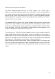
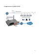
Chapter 1 Introduction 1.1 Introducing the BiPAC 7300GX Thank you for purchasing the BiPAC 7300GX ADSL2+ Router by Billion. Your new router is an all-in-one unit that combines an ADSL modem, ADSL2/2+ router , PC card slot for 3G/HSDPA data card and Ethernet network switch to provide everything you need to get the machines on your network connected to the Internet over an ADSL broadband connection.
internal users from accessing the Internet. The BiPAC 7300GX provides two levels of security support. First, it masks LAN IP addresses making them invisible to outside users on the Internet, so it is much more difficult for a hacker to target a machine on your network. Second, it can block and redirect certain ports to limit the services that outside users can access.
1.2 Features Express Internet Access – ADSL2/2+ capable The BiPAC 7300GX complies with ADSL worldwide standards. Supporting downstream rates of 8Mbps with ADSL, the router is capable of up to 12/24 Mbps with ADSL2/2+, and upstream rates of up to 1 Mbps. Users enjoy not only high-speed ADSL services but also broadband multimedia applications such as interactive gaming, video streaming and real-time audio which are easier and faster than ever. The router is compliant with Multi-Mode standard (ANSI T1.
Universal Plug and Play (UPnP) and UPnP NAT Traversal This protocol is used to enable simple and robust connectivity among stand-alone devices and PCs from many different vendors, and it makes setting up a network simple and affordable. UPnP architecture leverages TCP/IP and the Web to enable proximity networking in addition to control and data transfer among networked devices. With this feature enabled, you can seamlessly connect to Net Meeting or MSN Messenger.
Quality of Service (QoS) QoS gives you full control over which types of outgoing data traffic should be given priority by the router, ensuring important data like gaming packets, customer information, or management information move through the router ay lightning speed, even under heavy load. The QoS features are configurable by Internal IP address, External IP address, protocol, and port.
1.
Chapter 2 Product Overview Standards-Based Technology The BiPAC 7300GX Wireless Router utilizes the 802.11g standard. The IEEE 802.11g standard is an extension of the 802.11b standard. It increases the data rate up to 54Mbps* within the 2.4GHz band, utilizing OFDM technology. This means that in most environments, within the specified range of this device, you will be able to transfer large files quickly or even watch a movie in MPEG format over your network without noticeable delays.
(at least 3-6 feet or 1-2 meters) from electrical devices or appliances that generate extreme RF (radio frequency) noise. 2.1 Important Notes Do not use the BiPAC 7300GX in high humidity or high temperatures. Do not use the same power source for the BiPAC 7300GX as other equipment. Warning Do not open or repair the case yourself. If the BiPAC 7300GX is too hot, turn off the power immediately and have it repaired at a qualified service center. Avoid using this product and all accessories outdoors.
2.3 The Front LEDs LED Description 5 Power Lights Green when the power and router system are ready. Flickering Green when system is booting or system upgrade. Lights Red when device can not boot successfully. Lights off means power off. 6 3G Lights when 3G service is ready. 7 WLAN Lights Green when the wireless connection is established. Flashes when sending/receiving data. 8-11 Ethernet Port 1-4 Steady glow when connected to an Ethernet device. Glows green for 100Mbps; Orange for 10Mbps.
2.4 The Rear Ports 8 7 6 4 3 2 1 5 Port Description 1 Power Switch Power ON/OFF switch. 2 Power Connect the supplied power adapter to this jack. 3 3G card slot Connect the 3G card bus data card to this slot 4 After the router is powered on, press this reset button using the end of paper clip or other small pointed object to reset the router and to restore it to factory default settings. Reset 1. Recovery procedures for non-working routers (e.g. after a failed firmware upgrade flash). 2.
The detail instruction in Reset Button 1. Recovery procedures for non-working routers (e.g. after a failed firmware upgrade flash): Hold the Reset Button on the back of the modem in. Keep this button held in and turn on the modem. Once the lights on the modem have stopped flashing, release the Reset Button. The modem's emergency-reflash web interface will then be accessible via http://192.168.0.254 where you can upload a firmware image to restore the modem to a functional state.
2.5 Cabling One of the most common causes of problems is because of bad cabling or ADSL line(s). Make sure that all connected devices are turned on. On the front of the product is a bank of LEDs. Verify that the LAN Link and ADSL line LEDs are lit. If they are not, verify that you are using the proper cables. Ensure that all other devices connected to the same telephone line as your Billion router (e.g.
Chapter 3 Installation You can configure the BiPAC 7300GX router through the convenient and user-friendly interface of a web browser. Most popular operating systems such as Linux and Windows 98/NT/2000/XP/Me include a web browser as a standard application. 3.1 Before Configuration PCs must have a properly installed Ethernet interface which connects to the router directly or through an external repeater hub.
Configuring a PC in Windows XP 1. Go to Start / Control Panel (in Classic View). In the Control Panel, double-click on Network Connections 2. Double-click Local Area Connection. 3. In the Local Area Connection Status window, click Properties. 4. Select Internet Protocol (TCP/IP) and click Properties. 5. Select the Obtain an IP address automatically and the Obtain DNS server address automatically radio buttons. 6. Click OK to finish the configuration.
Configuring a PC in Windows 2000 1. Go to Start / Settings / Control Panel. In the Control Panel, double-click on Network and Dial-up Connections. 2. Double-click Local Area Connection. 3. In the Local Area Connection Status window click Properties. 4. Select Internet Protocol (TCP/IP) and click Properties. 5. Select the Obtain an IP address automatically and the Obtain DNS server address automatically radio buttons. 6. Click OK to finish the configuration.
Configuring PC in Windows 98/Me 1.Go to Start / Settings / Control Panel. In the Control Panel, double-click on Network and choose the Configuration tab. 2.Select TCP/IP ->NE2000 Compatible, or the name of your Network Interface Card (NIC) in your PC. 3.Select the Obtain an IP address automatically radio button. 4.Then select the DNS Configuration tab. 5.Select the Disable DNS radio button and click OK to finish the configuration.
Configuring PC in Windows NT4.0 1.Go to Start / Settings / Control Panel. In the Control Panel, double-click on Network and choose the Protocols tab. 2.Select TCP/IP Protocol and click Properties. 3.Select the Obtain an IP address from a DHCP server radio button and click OK.
3.2 Factory Default Settings Before configuring the BiPAC 7300GX router, you need to know the following default settings. Web Interface: (Username and Password) Username: admin Password: admin The default username and password are “admin” and “admin” respectively. If you ever forget the username/password to login to the router, you may press the RESET button up to 6 seconds then release it to restore the factory default settings.
3.3 LAN and WAN Port Addresses The parameters of LAN and WAN ports are preset at the factory. The default values are shown below. LAN Port WAN Port IP address 192.168.1.254 Subnet Mask 255.255.255.0 DHCP server function Enabled IP addresses for distribution to PCs 100 IP addresses continuing from 192.168.1.100 through 192.168.1.199 The PPPoE function is enabled to automatically get the WAN port configuration from the ISP, but you have to set the username and password first.
3.4 Information from your ISP Before configuring this device, you have to check with your ISP (Internet Service Provider) what kind of services are provided, such as PPPoE, PPPoA, MPoA or Pure Bridge. Gather the information as illustrated in the following table and keep it for reference. PPPoE VPI/VCI, VC-based/LLC-based multiplexing, Username, Password, Service Name, and Domain Name System (DNS) IP address (it can be automatically assigned by your ISP when you connect or be set manually).
3.5 Configuring with your BiPAC 7300GX 1. To configure this device, you must have IE 5.0 / Netscape 4.5 or above installed 2. You may configure the router for Internet access in two ways: (A) Easy Sign-On (EZSO) (B) Web Configuration Easy Sign On: After setting up the router with appropriate cables plugged, proceed to load the internet browser to surf Internet, the EZSO WEB GUI will be popped up and request you to input some basic information you get from ISP. After this, you can surf Internet right away.
3. Show Auto scan result - Protocol information. 4. Please enter “Username” and “Password” as supplied by your ISP (Internet Service Provider) and click continue. 5. Wait for the device to be configured.
6. You’ve have completed the WAN port setup and now click “next to wireless” to proceed to the wireless configuration. 7. Please configure the Wireless LAN setting and click Continue. 8. Save Configuration. 9. Congratulations!! You’ve completed the setup procedure and you are now ready to surf the Internet, enjoy.
Web Configuration: Open your web browser, enter the IP address of your router, which by default is 192.168.1.254, and click “Go”, a user name and password window prompt appears. The default username and password are “admin” and “admin”.
Chapter 4 Basic Configuration Once you have logged on to your BiPAC 7300GX ADSL2+ Router via your web browser, you can begin to set it up according to your requirements.
4.1 Status Device Information Model Name: Provide a name for the router for identification purposes. System Up-Time: Records system up-time. Hardware Version: Device version Software Version: Firmware version Port Status Port Status:User can look up to see if they are connected to Ethernet, ADSL, 3G or Wireless. WAN Port: Name of the WAN connection. Protocol VPI/VCI: Virtual Path Identifier and Virtual Channel Identifier Operation: The current status in WAN interface.
4.2 Quick Start Select WAN Port Connect Mode: User can choose either “ADSL” or “3G” mode. TEL No.: The dial string to make a GPRS / 3G user internetworking call. Username: The username provided by your service provider. APN: An APN is similar to a URL on the WWW, it is what the unit makes a GPRS / UMTS call.
Protocol: The current ATM protocol in the device. VPI / VCI: The current value of VPI/VCI in the device. Username: To show current authentication username. IP Address: To show current value of IP address in the device. Set Wireless configuration WLAN Service: Default setting is set to Enable. If you don’t want to use wireless, both 802.11g and 802.11b, device in your network, you can select Disable. ESSID: The ESSID is the unique name of a wireless access point (AP) to be distinguished from another.
4.3 WAN 3G Mode ( Main Port : 3G ) APN: An APN is similar to a URL on the WWW, it is what the unit makes a GPRS / UMTS call. The service provider is able to attach anything to an APN to create a data connection, requirements for APNs varies between different service providers. Most service providers have an internet portal which they use to connect to a DHCP Server, thus giving you access to the internet i.e. Some 3G operators use the APN ‘internet’ for their portal. The default value is “internet”.
Username: Enter the username provided by your service provider. Password: Enter the password provided by your service provider. PIN: PIN stands for Personal Identification Number. A PIN code is a numeric value used in certain systems as a password to gain access, and authenticate. In mobile phones a PIN code locks the SIM card until you enter the correct code.
provided by your ISP Auth. Protocol: Default is Auto. Your ISP advises on using Chap or Pap. IP Address: Your WAN IP address. Leave this at 0.0.0.0 to automatically obtain an IP address from your ISP. PPPoA Connection PPPoA stands for Point to Point Protocol over ATM Adaptation Layer 5 (AAL5). It provides access control and billing functionality in a manner similar to dial-up services using PPP. VPI/VCI: Enter the VPI and VCI information provided by your ISP.
VPI and VCI: Enter the VPI and VCI information provided by your ISP. Encap. method: Select the encapsulation format, the default is LLC. Select the one provided by your ISP. Encap. mode: Choose whether you want the packets in WAN interface as bridged packet or routed packet. IP Address: Your WAN IP address. Leave this at 0.0.0.0 to automatically obtain an IP address from your ISP. Netmask: The default is 255.255.255.0. User can change it to other such as 255.255.255.128.
4.4 WLAN Wireless Parameters WLAN Service: Default setting is set to Enable. If you don’t want to use wireless, both 802.11g and 802.11b, device in your network, you can select Disable. ESSID: The ESSID is the unique name of a wireless access point (AP) to be distinguished from another. For security propose, change to a unique ID name to the AP which is already built-in to the router’s wireless interface. It is case sensitive and must not excess 32 characters.
different based on this setting. Channel ID: Select the ID channel that you would like to use. Security Mode: You can disable or enable with WPA or WEP for protecting wireless network. The default mode of wireless security is Disable. Security Parameters WPA Pre-Shared Key WPA Shared Key: The key for network authentication. The input format is in character style and the key size should be in the range between 8 and 63 characters.
WEP Authentication: To prevent unauthorized wireless stations from accessing data transmitted over the network, the router offers secure data encryption, known as WEP. If you require high security for transmissions, there are three options to select from: Open System, Share key or Both. Default Used WEP Key: Select the encryption key ID; please refer to Key (1~4) below. Passphrase: This is used to generate WEP keys automatically based upon the input string and a pre-defined algorithm in WEP64 or WEP128.
Chapter 5 Advance Configuration Once you have logged on to your BiPAC 7300GX ADSL2+ Router via your web browser, you can begin to set it up according to your requirements.
5.1 Status Device Information Host Name: Provide a name for the router for identification purposes. Host Name lets you change the router name.
System Up-Time: Records system up-time. Current time: Set the current time. See the Time Zone section for more information. Hardware Version: Device version. Software Version: Firmware version. MAC Address: The LAN MAC address. WAN Port: Name of the WAN connection. Protocol VPI/VCI: Virtual Path Identifier and Virtual Channel Identifier Operation: The current status in WAN interface. Connection: The current connection status. IP Address: WAN port IP address. Net mask: WAN port IP subnet mask.
5.1.1 ADSL Status DSP Firmware Version: DSP code version DMT Status: Current DMT Status Operational Mode: To show the state when user select “AUTO” on connect mode. Upstream: Upstream rate. Downstream: Downstream rate. Noise Margin (Upstream): This is noise margin in upstream. Noise Margin (Downstream): This is noise margin in downstream. Attenuation (Upstream): This is attenuation of signal in upstream. Attenuation (Downstream): This is attenuation of signal in downstream.
5.1.2 3G Status This section displays the 3G Card’s overall status, which shows you a number of helpful information such as the current signal strength and statistics on current and total bytes transferred and received. Status: The current status of the 3G card. Signal Strength: The signal strength bar indicates current 3G signal strength. Network Name: The network name that the device is connected to.
5.1.2 ARP Table This section displays the router’s ARP (Address Resolution Protocol) Table, which shows the mapping of Internet (IP) addresses to Ethernet (MAC) addresses. This is useful as a quick way of determining the MAC address of the network interface of your PCs to use with the router’s Firewall – MAC Address Filter function. See the Firewall section of this manual for more information on this feature. IP Address: It is IP Address of internal host that join this network.
5.1.3 DHCP Table IP Address: The current corresponding DHCP-assigned dynamic IP address of the device. MAC Address: The MAC Address of internal dhcp client host. Client Host Name: The Host Name of internal dhcp client.
5.1.4 System Log Display system logs accumulated up to the present time. You can trace historical information with this function.
5.1.5 Firewall Log Firewall Log display log information of any unexpected action with your firewall settings. This page displays the router’s Firewall Log entries. The log shows log entries when you have enabled Intrusion Detection or Block WAN PING in the Configuration – Firewall section of the interface. Please see the Firewall section of this manual for more details on how to enable Firewall logging.
5.2 Quick Start For detailed instructions on configuring WAN settings, see the WAN section of this manual. The information you need for the Quick Start wizard to get you online are your login (often in the form of username@ispname), your password, and the encapsulation type. Your ISP can supply all the details you need.
Select WAN Port Connect Mode: User can choose either “ADSL” or “3G” mode. Protocol: The current ATM protocol in the device. VPI / VCI: The current value of VPI/VCI in the device. Username: To show current authentication username. IP Address: To show current value of IP address in the device. TEL No.: The dial string to make a GPRS / 3G user internetworking call. Username: The username provided by your service provider.
WLAN Service: Default setting is set to Enable. If you don’t want to use wireless, both 802.11g and 802.11b, device in your network, you can select Disable. ESSID: The ESSID is the unique name of a wireless access point (AP) to be distinguished from another. For security propose, change to a unique ID name to the AP which is already built-in to the router’s wireless interface. It is case sensitive and must not excess 32 characters.
5.3 Configuration Click this item to access the following sub-items that configure the ADSL router: LAN, WAN, System, Firewall, QoS, Virtual Server, Time Schedule and Advanced. These functions are described in the following sections.
5.3.1 LAN (Local Area Network) A Local Area Network (LAN) is a shared communication system to which many computers are attached and is limited to the immediate area, usually the same building or floor of a building. There are six items within the LAN section: Ethernet, IP Alias, Wireless, Wireless Security, WPS and DHCP Server. 5.3.1.
The router supports more than one Ethernet IP addresses in the LAN, and with distinct LAN subnets through which you can access the Internet at the same time. Users usually only have one subnet in their LAN. The default IP address for the router is 192.168.1.254. IP Address: The default IP on this router. Netmask: The default subnet mask on this router. RIP: RIP v1, RIP v2, RIP v1+v2 and RIP v2 Multicast. 5.3.1.2 IP Alias This function allows the creation of multiple virtual IP interfaces on this router.
5.3.1.3 Wireless Parameters WLAN Service: Default setting is set to Enable. If you don’t want to use wireless, both 802.11g and 802.11b, device in your network, you can select Disable. Mode: The default setting is 802.11b+g (Mixed mode). If you do not know or have both 11g and 11b devices in your network, then keep the default in mixed mode. From the drop-down manual, you can select 802.11g if you have only 11g card. If you have only 11b card, then select 802.11b.
Regulation Domain: There are seven Regulation Domains for you to choose from, including North America (N.America), Europe, France, etc. The Channel ID will be different based on this setting. Channel ID: Select the ID channel that you would like to use. Tx Power Level: It is function that enhances the wireless transmitting signal strength. User may adjust this power level from minimum 0 up to maximum 255.
5.3.1.4 Wireless Security You can disable or enable with WPA or WEP for protecting wireless network. The default mode of wireless security is Disable. WPA1 Pre-Shared Key WPA Algorithms: TKIP (Temporal Key Integrity Protocol) / AES(Advanced Encryption Standard) utilizes a stronger encryption method and incorporates Message Integrity Code (MIC) to provide protection against hackers. WPA Shared Key: The key for network authentication.
WPA2 Pre-Shared Key WPA Algorithms: TKIP (Temporal Key Integrity Protocol) / AES(Advanced Encryption Standard) utilizes a stronger encryption method and incorporates Message Integrity Code (MIC) to provide protection against hackers. WPA Shared Key: The key for network authentication. The input format is in character style and key size should be in the range between 8 and 63 characters.
string and a pre-defined algorithm in WEP64 or WEP128. You can input the same string in both the AP and Client card settings to generate the same WEP keys. Please note that you do not have to enter Key (1-4) as below when the Passphrase is enabled. Key (1-4): Enter the key to encrypt wireless data. To allow encrypted data transmission, the WEP Encryption Key values on all wireless stations must be the same as the router. There are four keys for your selection.
Step 3: Enter AP’s PIN into the utility and click on the “next” button. Step 4: These are two ways to trigger AP as Enrolee role, you can choose one to do it. Push AP’s WPS button 1 second and release it. Or In the AP’s WPS configuration page, change Role to “Enrollee” and apply “Start” button.
Step 5: Jumpstart WPS utility search WPS AP. Step 6: SSID and security will be generated automatically (You can change it) and apply “next” button.
Step 7: WPS set up complete. And you have set up security-enabled Wi-Fi networks.
Set up of security-enabled Wi-Fi network using WCN in Vista Step 1: Note down the AP’s PIN from Web (Ex: 78749887). Step 2: Set WPS State to “Unconfigured” at Wireless page and click “Apply”. Step 3: In Vista`s Control Panel, select Network and Internet and choose View network computers and devices. Double click the “ADSL Firewall Router” icon and enter the AP`s PIN code then click “Next”.
Step 4: Enter the AP SSID and apply “Next” button.
Step 5: Enter the Passphrase and apply “Next” button. Step 6: WCN set up complete. And you have set up security-enabled Wi-Fi networks.
Adding a new WPS device (wireless client) to a network - Use PBC Method Step 1: Push AP’s WPS button more than one second and you will see AP’s WLAN led will flashing per second. Step 2: Open wireless client’s WPS utility, select “Join a wireless network” and apply “next” button. Note: After you push AP’s WPS button, below steps should be completed between 2 minutes. Step 3: Select “Push the button on my access point” and apply “next” button.
Step 4: New WPS device have join into the wireless network. Adding a new WPS device (wireless client) to a network - Use PIN Method Step 1: Open wireless client’s WPS utility, select “Join a wireless network” and apply “next” button.
Step 2: Note down the wireless client’s PIN (Ex: 41538142) and apply “Start” button for active wireless client WPS PIN method. Step 3: Enter wireless client’s PIN into “Enrollee’s PIN” of Web and apply “Start” button. Step 4: New WPS device have join into the wireless network.
Adding a new WPS device (wireless client) to a network - Use PIN Method Step 1: Open wireless client’s WPS utility, select “Join a wireless network” and apply “next” button. 5.3.1.6 DHCP Server You can disable or enable the DHCP (Dynamic Host Configuration Protocol) server or enable the router’s DHCP relay functions. The DHCP protocol allows your router to dynamically assign IP addresses to PCs on your network if they are configured to obtain IP addresses automatically.
DHCP Server Mode: DHCP Server To configure the router’s DHCP Server, check DHCP Server. You can then configure parameters of the DHCP Server including the IP pool (starting IP address and ending IP address to be allocated to PCs on your network), lease time for each assigned IP address (the period of time the IP address assigned will be valid), DNS IP address and the gateway IP address. These details are sent to the DHCP client (i.e. your PC) when it requests an IP address from the DHCP server.
which assigns an IP address back to the DHCP client in the LAN. Use this function only if advised to do so by your network administrator or ISP. Click Apply to enable this function.
5.3.2 WAN (Wide Area Network) A WAN (Wide Area Network) is an outside connection to another network or the Internet. There are three items within the WAN section: WAN Interface, WAN Profile and ADSL Mode. 5.3.2.1 WAN Interface The factory default has the Connection Mode as ADSL and the Protocol as PPPoE.
Main Port: User can select either “ADSL” or “3G” mode. Failover / Failback: Set Enable to trigger ADSL / 3G failover / failback function ready. Note: If 3G is set for main port, then there can be no option for failover/failback. Backup Port: It links to backup port configuration page. It is necessary to configure it when Failover/Failback be set. Connectivity Decision: Set how many times of probing failed to switch backup port.
Rule 1. ADSL Down Rule 2. Ping Fail No Ping: It will not send any ping packet to determine the connection. It means to disable the ping fail detection. Ping Gateway: It will send ping packet to gateway and wait response from gateway in every “Probe Cycle”. Ping Host: It will send ping packet to specific host and wait response in every “Probe Cycle”. The host must be an IP address. Notification: Select Enable to send mail to notify the Failover/Failback occurred.
This is an example of Failover/Failback function. The device will determine ADSL status and send ping packet to Gateway every 60 seconds. It will determine if the ADSL is Down or not replying from Gateway. If this happens 5 times continuously, the device will switch to 3G mode and try to establish the internet connection. Device will send a mail to abc@xxx.yyy.zzz via smtp server xxx.yyy.zzz to tell user(abc@xxx.yyy.zzz) this event had occurred.
Description: A user-definable name for this connection. VPI/VCI: Enter the VPI and VCI information provided by your ISP. Encap. method: Select the encapsulation format, the default is LLC. Select the one provided by your ISP Username: Enter the username provided by your ISP. You can input up to 128 alphanumeric characters (case sensitive). This is in the format of “username@ispname” instead of simply “username”. Password: Enter the password provided by your ISP.
program on your computer attempts to access the Internet). In this mode, you must set Idle Timeout value at same time. Idle Timeout: Auto-disconnect the broadband firewall gateway when there is no activity on the line for a predetermined period of time. The minimum value is 10 minutes. MTU: Maximum Transmission Unit. The size of the largest datagram (excluding media-specific headers) an IP attempts to send through the interface. Obtain DNS Automatically: Select this check box to use DNS.
have public IP addresses and can access the Internet directly, the NAT function can be disabled. IP Address: Your WAN IP address. Leave this at 0.0.0.0 to automatically obtain an IP address from your ISP. Authentication Protocol Type: Default is Auto. Your ISP should advises you on whether to use Chap or Pap. Connection: Always on: The router will establish a PPPoA session when starting up and to automatically re-establish the PPPoA session when disconnected by the ISP.
provided by your ISP. Encap. mode: Choose whether you want the device to function as bridge mode or routing mode. NAT: The NAT (Network Address Translation) feature allows multiple users to access the Internet through a single IP account, sharing the single IP address. If users on your LAN have public IP addresses and can access the Internet directly, the NAT function can be disabled. IP Address: Your WAN IP address. Leave this at 0.0.0.0 to automatically obtain an IP address from your ISP.
TEL No.: The dial string to make a GPRS / 3G user internetworking call. It may provide by your mobile service provider. APN: An APN is similar to a URL on the WWW, it is what the unit makes a GPRS / UMTS call. The service provider is able to attach anything to an APN to create a data connection, requirements for APN’s to be assigned varies between different service providers. Most service providers have an internet portal which they connect a DHCP Server to, giving you access to the internet i.e.
Keep Alive: Set Enable to allow the router automatically reconnects the connection when ISP disconnects it. Connect to Demand: If you want to make UMTS/GPRS call only when there is a packet requesting access to the Internet (i.e. when a program on your computer attempts to access the Internet). In this mode, you must set Idle Timeout value at same time. Enabling Connect on Demand will give you an option of Idle Timeout.
80
5.3.3 System There are five items within the System section: Time Zone, Firmware Upgrade, Backup/Restore, Restart and User Management.
5.3.3.1 Time Zone The router does not have a real time clock on board; instead, it uses the Simple Network Time Protocol (SNTP) to get the current time from an SNTP server outside your network. Choose your local time zone, click Enable and click the Apply button. After a successful connection to the Internet, the router retrieves the correct local time from the SNTP server you have specified.
5.3.3.2 Firmware Upgrade Your router’s “firmware” is the software that allows it to operate and provides all its functionality. Think of your router as a dedicated computer, and the firmware as the software it runs. Over time this software may be improved and modified. Your router allows you to upgrade the software it runs to take advantage of these changes. Clicking on Browse allows you to select the new firmware image file you have downloaded to your PC.
5.3.3.3 Backup / Restore These functions allow you to save and backup your router’s current settings to a file on your PC, or to restore a previously saved backup. This is useful if you wish to experiment with different settings, knowing that you have a backup handy in the case of any mistakes. It is advisable to backup your router’s settings before making any significant changes to your router’s configuration. Press Backup to select where on your local PC to save the settings file.
If you wish to restart the router using the factory default settings (for example, after a firmware upgrade or if you have saved an incorrect configuration), select Factory Default Settings to reset to factory default settings. You may also reset your router to factory settings by holding the small Reset pinhole button more than 6 seconds on the back of your router. Caution: After pressing the RESET button for more than 6 seconds and release it, the system will be restarted with the factory setting. 5.3.3.
5.3.4 Firewall Firewall and Access Control Your router includes a full SPI (Stateful Packet Inspection) firewall for controlling Internet access from your LAN, as well as helping to prevent attacks from hackers. In addition to this, when using NAT (Network Address Translation) the router acts as a “natural” Internet firewall, since all PCs on your LAN use private IP addresses that cannot be directly accessed from the Internet. See the WAN configuration section for more details on NAT.
prevent unauthorized computers or applications accessing your local network from the Internet. Intrusion Detection: Enable Intrusion Detection to detect, prevent, and log malicious attacks. MAC Filter rules: Prevents unauthorized computers accessing the Internet. URL Filter: Blocks PCs on your local network from unwanted websites.
Rule Name: Users-define description to identify this entry. The maximum name length is 32 characters, and then can choose application that they want from listbox. Internal IP Address / External IP Address: This is the Address-Filter used to allow or block traffic to/from particular IP address(es). Input the range you want to filter out. If you leave empty or 0.0.0.0, it means any IP address. Protocol: Specify the packet type (TCP, UDP, ICMP, etc.) that the rule applies to.
Attention If the DHCP server option is enabled, you must be very careful in assigning IP addresses of a filtered private IP range to avoid conflicts because you do not know which PC in the LAN is assigned which IP address. The easiest and safest way is that the filtered IP address is assigned to a specific PC that is not allowed to access an outside resource such as the Internet. You configure the filtered IP address manually for this PC, but it stays in the same subnet with the router. 5.3.4.
5.3.4.3 Intrusion Detection Check Enable if you wish to detect intruders accessing your computer without permission. The router automatically detects and blocks a DoS (Denial of Service) attack if a user enables this function. This kind of attack is not to access confidential data on the network; instead, it aims to disrupt specific equipment or the entire network. If this happens, users will have trouble accessing the network resources.
Intrusion Detection. For SYN Flood, ICMP Echo Storm and ICMP flood, IDS will just warn the user in the Event Log but it will not be able to protect against such attacks.
(Default 100 c/sec) ICMP Flood ICMP Echo Max ICMP Count (Default 100 c/sec) Max PING Count (Default 15 c/sec) Src IP: Source IP Src Port: Source Port Dst Port: Destination Port Dst IP: Destination IP Yes Yes 5.3.4.4 Block WAN PING Check Enable if you wish to exclude outside PING requests from reaching this router. 5.3.4.5 URL Filter URL (Uniform Resource Locator – e.g. an address in the form of http://www.billion.com or http://www.example.
Keywords Filtering: Allows blocking by specific keywords within a particular URL rather than having to specify a complete URL (e.g. to block any image called “advertisement.gif”). When enabled, your specified keywords list is checked to see if any keywords are present in URLs accessed to determine if the connection attempt should be blocked. Note that the URL filter blocks web browser (HTTP) connection attempts using port 80 only. For example, the URL http://www.abc.com/abcde.
Restrict URL Features: This function enhances the restriction to your URL rules. Block Java Applet: Blocks Web content which includes the Java Applet to prevent someone who wants to damage your system via the standard HTTP protocol. Block ActiveX: Blocks ActiveX Block Cookies: Blocks Cookies Block Proxy: Blocks Proxy Except IP Address: Time Schedule: It is self-defined time period. You may specify a time schedule for your prioritization policy. For setup and detail, refer to Time Schedule section.
5.3.5 QoS (Quality of Service) Quality of Service Introduction If you’ve ever found your ‘net’ speed has slowed to a crawl because another family member is using a P2P file sharing program, you’ll understand why the Quality of Service features in Billion’s routers is such a breakthrough for home users and office users.
Direction: The traffic flow direction to be controlled by the QoS policy. There are two settings to be provided in the Router: LAN to WAN: You want to control the traffic flow from the local network to the outside world. e.g., you have a FTP server inside the local network and you want to have a limited traffic rate controlled by the QoS policy. So, you need to add a policy with LAN to WAN direction setting. WAN to LAN: Control Traffic flow from the WAN to LAN.
Silver service (M) Class 2, Silver (010100) Silver service (H) Class 2, Bronze (010110) Bronze service (L) Class 3, Gold (011010) Bronze service (M) Class 3, Silver (011100) Bronze service (H) Class 3, Bronze (011110) Rate Type: 2 types are provided: Limited (Maximum): specify a limited data rate for this policy. It also is the maximal rate for this policy. As above FTP server example, you may want to “throttle” the outgoing FTP speed to 20% of 256K and limit to it, you may use this type.
from WAN to LAN, it is the destination port value.) External IP Address: The IP address values for Remote WAN machines you want to control. (For IP packets from LAN to WAN, it is the destination IP address. For IP packages from WAN to LAN, it is the source IP address.) External Ports: The Application port values for remote machines you want to control. (For TCP/UDP packets from LAN to WAN, it is the destination port value. For TCP/UDP packets from WAN to LAN, it is the source port value.
DSCP marking Class 1 Gold Service. FTP Sever 192.168.0.100 Incoming Outgoing and outgoing :minimal 30%. Data Only rate. Working Hours 9:00 to incoming :minimal 30%. Data 17:00 Monday rate. to Friday. Both with low priority for non-used bandwidth. HTTP web 80 Incoming browsing Outgoing users and outgoing : limited 20%. Data Always rate. incoming : limited 30%. Data rate. Example QoS Setup VoIP application Voice is latency-sensitive application.
5.3.6 Virtual Server In TCP and UDP networks a port is a 16-bit number used to identify which application program (usually a server) incoming connections should be delivered to. Some ports have numbers that are pre-assigned to them by the IANA (the Internet Assigned Numbers Authority), and these are referred to as “well-known ports”. Servers follow the well-known port assignments so clients can locate them. If you wish to run a server on your network that can be accessed from the WAN (i.e.
to 65535, but only port numbers 0 to 1023 are reserved for privileged services and are designated as “well-known ports”. The registered ports are numbered from 1024 through 49151. The remaining ports, referred to as dynamic ports, or private ports, are numbered from 49152 through 65535. Examples of well-known and registered port numbers are shown below, for further information, please see IANA’s website at: http://www.iana.
5.3.6.1 Port Mapping Application: Select the service you wish to configure Protocol: Automatic when you choose Application from listbox or select a protocol type which you want. External Port & Internal Port: Enter the public port number & range you wish to configure. Internal IP Address: Enter the IP address of a specific internal server to which requests from the specified port is forwarded. Add: Click to add a new virtual server rule. Click again and the next figure appears. Edit: Check the Rule No.
In addition to specifying the port number used, you also need to specify the protocol used. The protocol is determined by the particular application. Most applications use TCP or UDP, however you can specify other protocols using the drop-down Protocol menu. Setting the protocol to “all” causes all incoming connection attempts using all protocols on all port numbers to be forwarded to the specified IP address. 5.3.6.2 DMZ DMZ: The DMZ Host is a local computer exposed to the Internet.
Using port mapping does have security implications, since outside users are able to connect to PCs on your network. For this reason you are advised to use specific Virtual Server entries just for the ports your application requires instead of simply using DMZ or creating a Virtual Server entry for “All” protocols, as doing so results in all connection attempts to your public IP address accessing the specified PC. Attention 1.
5.3.7 Time Schedule The Time Schedule supports up to 16 time slots which helps you to manage your Internet connection. In each time profile, you may schedule specific day(s) i.e. Monday through Sunday to restrict or allowing the usage of the Internet by users or applications. This Time Schedule correlates closely with router’s time, since router does not have a real time clock on board; it uses the Simple Network Time Protocol (SNTP) to get the current time from an SNTP server from the Internet.
Start Time: The default is set at 8:00 AM. You may specify the start time of the schedule. End Time: The default is set at 18:00 (6:00PM). You may specify the end time of the schedule. Select the Apply button to apply your changes.
5.3.8 Advanced Configuration options within the Advanced section are for users who wish to take advantage of the more advanced features of the router. Users who do not understand the features should not attempt to reconfigure their router, unless advised to do so by support staff. There are seven items within the Advanced section: Static Route, Dynamic DNS, Device Management, IGMP, WAN IP Change Alert, SNMP Access Control and Remote Access.
5.3.8.1 Static Route Destination: The destination subnet IP address. Netmask: Subnet mask of the destination IP addresses based on above destination. Gateway: The gateway IP address to which packets are forwarded. Interface: Select the interface through which packets are forwarded. Cost: Represents the cost of transmission for routing purposes. The number need not be precise, but it must be between 0 and 65535. 5.3.8.
There are more than 5 DDNS services supported. Disable: Check to disable the Dynamic DNS function. Enable: Check to enable the Dynamic DNS function. The fields following are activated and required. Dynamic DNS Server: Select the DDNS service you have established an account with. Wildcard: Select this check box to enable the DYNDNS Wildcard. Domain Name, Username and Password: Enter your registered domain name and your username and password for this service.
5.3.8.3 Device Management The Device Management advanced configuration settings allow you to control your router’s security options and device monitoring features. Embedded Web Server: HTTP Port: The port number of the router’s embedded web server (for web-based configuration uses. The default value is the standard HTTP port, 80. You may specify an alternative if, for example, you are running a web server on a PC within your LAN.
Disable: Check to disable the router’s UPnP functionality. Enable: Check to enable the router’s UPnP functionality. UPnP Port: The Default setting is 2800. It is highly recommended you use this port value. If this value conflicts with other ports already in use you may wish to change the port. Installing UPnP in Windows Example Follow the steps below to install the UPnP in Windows Me. Step 1: Click Start and Control Panel. Double-click Add/Remove Programs.
Step 4: Click OK to go back to the Add/Remove Programs Properties window. Click Next. Step 5: Restart the computer when prompted. Follow the steps below to install the UPnP in Windows XP. Step 1: Click Start and Control Panel. Step 2: Double-click Network Connections. Step 3: In the Network Connections window, click Advanced in the main menu and select Optional Networking Components …. The Windows Optional Networking Components Wizard window displays.
Step 5: In the Networking Services window, select the Universal Plug and Play check box. Step 6: Click OK to go back to the Windows Optional Networking Component Wizard window and click Next.
Auto-discover Your UPnP-enabled Network Device Step 1: Click start and Control Panel. Double-click Network Connections. An icon displays under Internet Gateway. Step 2: Right-click the icon and select Properties. Step 3: In the Internet Connection Properties window, click Settings to see the port mappings that were automatically created.
Step 4: You may edit or delete the port mappings or click Add to manually add port mappings. Step 5: Select Show icon in notification area when connected option and click OK. An icon displays in the system tray Step 6: Double-click on the icon to display your current Internet connection status.
Web Configurator Easy Access With UPnP, you can access web-based configuration for the BiPAC 7300GX without first finding out the IP address of the router. This helps if you do not know the router’s IP address. Follow the steps below to access web configuration. Step 1: Click Start and then Control Panel. Step 2: Double-click Network Connections. Step 3: Select My Network Places under Other Places. Step 4: An icon describing each UPnP-enabled device shows under Local Network.
IGMP Proxy: Accepting multicast packet. Default is set to Disable. IGMP Snooping: Allowing switched Ethernet / Wireless to check and make correct forwarding decisions. Default is set to Disable. 5.3.8.5 WAN IP Change Alert Send a log via Email When WAN IP is changed. Default is set to Disable. Recipient’s E-mail: Set the Recipient’s email address to which the email notification is sent. SMTP server: Set the SMTP (mail) server address. 5.3.8.
SNMP V1 and V2: Read Community: Specify a name to be identified as the Read Community, and an IP address. This community string will be checked against the string entered in the configuration file. Once the string name is matched, user obtains this IP address will be able to view the data. Write Community: Specify a name to be identified as the Write Community, and an IP address. This community string will be checked against the string entered in the configuration file.
Traps supported: Cold Start, Authentication Failure.
ifMIBObjects Group From RFC1695 (atmMIB): atmMIBObjects From RFC 1907 (SNMPv2): only snmpSetSerialNo OID 5.3.8.7 Remote Access Remote Access Control: Enable: Select Enable to allow management access from remote side (mostly from internet). Duration: Set how many minutes to allow management access from remote side. Zero means always on. Allowed Access IP Address Range: Valid: Select Valid to allow remote management from these IP ranges.
5.4 Save Configuration to Flash After changing the router’s configuration settings, you must save all of the configuration parameters to FLASH to avoid losing them after turning off or resetting your router. Click “Save Config“ and click “Apply” to write your new configuration to FLASH.
5.5 Restart Click Restart with option Current Settings to reboot your router (and restore your last saved configuration). If you wish to restart the router using the factory default settings (for example, after a firmware upgrade or if you have saved an incorrect configuration), select Factory Default Settings to reset to factory default settings. You may also reset your router to factory settings by holding in the small Reset pinhole button on the back of your router over 6 seconds then release it.
5.6 Logout To exit the router’s web interface, choose Logout. Please ensure that you have saved the configuration settings before you logout. Be aware that the router is restricted to only one PC accessing the configuration web pages at a time. Once a PC has logged into the web interface, other PCs cannot get access until the current PC has logged out of the web interface. If the previous PC forgets to logout, the second PC can access the page after a user-defined period, by default 30 minutes.
Chapter 6 Troubleshooting If your ADSL Router is not functioning properly, you can refer first to this chapter for simple troubleshooting before contacting your service provider or Billion support. This can save you time and effort but if symptoms persist, consult your service provider. Problems starting up the router None of the LEDs Check the connection between the adapter and the router. If are on when you the error persists, you may have a hardware problem. In this turn on the router.
Frequent loss ADSL linesync telephone line as your router (e.g. telephones, fax machines, (disconnections). of Ensure that all other devices connected to the same analogue modems) have a line filter connected between them and the wall socket (unless you are using a Central Splitter or Central Filter installed by a qualified and licensed electrician), and ensure that all line filters are correctly installed and the right way around.