BiPAC 8920AX(L) Dual-lines VDSL2/ADSL2+ Wireless-AC (VPN) Firewall Router User Manual Version Released: 2.50a.
Table of Contents Chapter 1: Introduction .................................................................................................................................. 1 Introduction to your Router..................................................................................................................... 1 Features ................................................................................................................................................... 3 VDSL2/ADSL2+ Compliance .......
Quick Start.............................................................................................................................................. 52 Quick Start....................................................................................................................................... 52 Configuration ......................................................................................................................................... 57 LAN ‐ Local Area Network .........................
One‐to‐One NAT .................................................................................................................... 164 Port Triggering ....................................................................................................................... 165 ALG ......................................................................................................................................... 168 Wake On LAN ..............................................................................
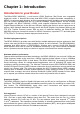
Chapter 1: Introduction Introduction to your Router The Billion BiPAC 8920AX(L) , a multi service VDSL2 Dual-lines (30a) Router over comparable single-port model. It features fibre-ready dual-WAN VDSL2 supports backward compatibility to ADSL2+ for a longer reach distance, an all-in-one advanced device including concurrent dual-band 802.11ac (5GHz) 1300Mbps and 802.11n (2.4GHz) 300Mbps, Gigabit Ethernet.
IPv6 also implements new features that simplify aspects of address assignment (stateless address autoconfiguration) and network renumbering (prefix and router announcements) when changing Internet connectivity providers. The IPv6 subnet size has been standardized by fixing the size of the host identifier portion of an address to 64 bits to facilitate an automatic mechanism for forming the host identifier from Link Layer media addressing information (MAC address).
Features • Compliant with all ADSL2+/VDSL2 standards • IPv6 ready (IPv4/IPv6 dual stack) • Dual- WAN approach – VDSL2/ADSL2+, and Ethernet WAN for Broadband Connectivity • 5-port Gigabit Ethernet switch • 1-port (Port#5) Gigabit Ethernet WAN (EWAN) port for broadband connectivity. • Compliant with IEEE 802.
Annex M, available for BiPAC 8920AX(L)A model only) - Full-rate ANSI T1.413 Issue 2 - ITU-T G.992.1 (G.dmt) - ITU-T G.992.2 (G.lite) - ITU-T G.994.1 (G.
• MAC filtering • Password protection for system management Quality of Service Control • Supports the DiffServ approach • Traffic prioritization and bandwidth management based-on IPv4/IPv6 protocol, port number and address ATM and PPP Protocols • ATM Adaptation Layer Type 5 (AAL5) • Multiple Protocol over ALL5 (RFC 268, formerly RFC 1483) • Bridged or routed Ethernet encapsulation • VC and LLC based multiplexing • PPP over Ethernet (PPPoE) • PPP over ATM (RFC 2364) • Classical IP over ATM (RFC 1577) • MAC
USB Application Server • Storage/NAS: FTP server, Samba server,DLNA • Printer Server Virtual Private Network (VPN) (8920AX only) • IKE key management • DES, 3DES and AES encryption for IPSec • L2TP over IPSec • Pap/ Chap/ MS-CHAPv2 authentication for PPTP • IPSec pass-through • GRE tunnel Management • Easy Sign-on (EZSO) • Web-based GUI for remote and local management (IPv4/IPv6) • Firmware upgrades and configuration data upload and download via web-based GUI • Embedded Telnet server for remote and local
Hardware Specifications Physical Interface • WLAN: 3 external antennas • DSL: VDSL port • USB 2.0: 1-port USB 2.
Chapter 2: Installing the Router Package Contents • BiPAC 8920AX(L) Dual-lines VDSL2/ADSL2+ Wireless-AC (VPN) Firewall Router • Quick Start Guide • CD containing the on-line manual • Vertical Stand • RJ-45 Cat.
Important note for using this router 1. Do not use the router in high humidity or high temperatures. 2. Do not use the same power source for the router as other equipment. 3. Do not open or repair the case yourself. If the router is too hot, turn off the power immediately and have it repaired at a qualified service center. 4. Avoid using this product and all accessories outdoors. Warning 1. Place the router on a stable surface. 2. Only use the power adapter that comes with the package.
Device Description The Front LEDs LED Status Meaning Red Boot failure or in emergency mode Green System ready Green Connected to an Gigabit Ethernet device or to a broadband connection device.
The Rear Ports Port Meaning 1 1 ON/OFF Power ON / OFF switch. PWR Connect the supplied power adapter to this jack. 2 2 3 4 3 By controlling the pressing time, users can achieve two different effects: WPS /Wireless (1) WPS: Press &hold the button for less than 6 seconds to trigger on/off button WPS function. (2) Wireless ON/OFF button: Press & hold the button for more than 6 seconds to On/Off the wireless.
Cabling One of the most common causes of problems is bad cabling or ADSL line(s). Make sure that all connected devices are turned on. On the front panel of your router is a bank of LEDs. Verify that the LAN Link and ADSL line LEDs are all lit. If they are not, verify if you are using the proper cables. If the error persists, you may have a hardware problem. In this case, you should contact technical support. Make sure you have a line filter with all devices (e.g.
Chapter 3: Basic Installation The router can be configured through your web browser. A web browser is included as a standard application in the following operating systems: Linux, Mac OS / Windows 8, Windows 7 / 98 / NT / 2000 / XP / Me / Vista, etc. The product provides an easy and user-friendly interface for configuration. Please check your PC network components. The TCP/IP protocol stack and Ethernet network adapter must be installed.
Connecting Your Router Users can connect the ADSL2+ router as the following.
- two-paired 15
Broadband Router mode: 16
Network Configuration Configuring a PC in Windows 7/ 8 1. Go to Start. Click on Control Panel. Then click on Network and Internet. 2. When the Network and Sharing Center window pops up, select and click on Change adapter settings on the left window panel. 3. Select the Local Area Connection, and right click the icon to select Properties.
IPv4: 4. Select Internet Protocol Version 4 (TCP/IPv4) then click Properties 5. In the TCP/IPv4 properties window, select the Obtain an IP address automatically and Obtain DNS Server address automatically radio buttons. Then click OK to exit the setting. 6. Click OK again in the Local Area Connection Properties window to apply the new configuration.
IPv6: 4. Select Internet Protocol Version 6 (TCP/IPv6) then click Properties 5. In the TCP/IPv6 properties window, select the Obtain an IPv6 address automatically and Obtain DNS Server address automatically radio buttons. Then click OK to exit the setting. 6. Click OK again in the Local Area Connection Properties window to apply the new configuration.
Configuring a PC in Windows Vista 1. Go to Start. Click on Network. 2. Then click on Network and Sharing Center at the top bar. 3. When the Network and Sharing Center window pops up, select and click on Manage network connections on the left window pane. 4. Select the Local Area Connection, and right click the icon to select Properties.
IPv4: 5. Select Internet Protocol Version 4 (TCP/IPv4) then click Properties. 6. In the TCP/IPv4 properties window, select the Obtain an IP address automatically and Obtain DNS Server address automatically radio buttons. Then click OK to exit the setting. 7. Click OK again in the Local Area Connection Properties window to apply the new configuration.
IPv6: 8. Select Internet Protocol Version 6 (TCP/IPv6) then click Properties. 9. In the TCP/IPv6 properties window, select the Obtain an IPv6 address automatically and Obtain DNS Server address automatically radio buttons. Then click OK to exit the setting. 10. Click OK again in the Local Area Connection Properties window to apply the new configuration.
Configuring a PC in Windows XP IPv4: 1. Go to Start / Control Panel (in Classic View). In the Control Panel, double-click on Network Connections 2. Double-click Local Area Connection. 3. In the Local Area Connection Status window, click Properties. 4. Select Internet Protocol (TCP/IP) and click Properties. 5. Select the Obtain an IP address automatically and the Obtain DNS server address automatically radio buttons. 6. Click OK to finish the configuration.
IPv6: IPv6 is supported by Windows XP, but you should install it first. Act as shown below: 1. On the desktop, Click Start > Run, type cmd, then press Enter key in the keyboard, the following screen appears. 2. Key in command ipv6 install Configuration is OK now, you can test whether it works ok.
Factory Default Settings Before configuring your router, you need to know the following default settings. Web Interface (Username and Password) Three user levels are provided by this router, namely Administrator, Remote and Local respectively. See Access Control .
LAN and WAN Port Addresses The parameters of LAN and WAN ports are pre-set in the factory. The default values are shown in the table. IPv4 LAN Port IPv4 address Subnet Mask DHCP server function IP addresses for distribution to PCs WAN Port 192.168.1.254 255.255.255.0 Enabled 100 IP addresses continuing from 192.168.1.100 through 192.168.1.199 The PPPoE function is enabled to automatically get the WAN port configuration from the ISP.
Information from your ISP Before configuring this device, you have to check with your ISP (Internet Service Provider) to find out what kind of service is provided. Gather the information as illustrated in the following table and keep it for reference. PPPoE(RFC2516) VPI/VCI, VC / LLC-based multiplexing, Username, Password, Service Name, and Domain Name System (DNS) IP address (it can be automatically assigned by your ISP when you connect or be set manually).
Easy Sign On (EZSO) This special feature makes it easier for you to configure your router so that you can connect to the internet in a matter of seconds without having to logon to the router GUI for any detail configuration. This configuration method is usually auto initiated if user is to connect to the internet via Billion's router for the first time.
If the DLS line doesn’t synchronize, the page will pop up warning of the DSL connection failure. 3. Wait while the device is configured (DSL synchronized). 4. WAN port configuration is success and next to wireless, if you want skip wireless setting, click Done. Click Done, web configuration will be loaded, you will enter the web configuration page. 5. After the configuration is successful, click Next to Wireless button and you may proceed to configure the Wireless setting.
6. Continue to set 2.4GHz wireless. 7. Success in configuring the EZSO.
Ethernet mode 1. Select Ethernet, press Continue to go on to next step. 2. Enter the username, password from your ISP, for IP and DNS settings, also refer to your ISP. Here IPv6 service is enabled by default. 3. Wait while the device is configured. 4. WAN port configuration is success. Click Done, web configuration will be loaded, you will enter the web configuration page.
5. After the configuration is successful, click Next to Wireless button and you may proceed to configure the Wireless setting. The 8920AX(L) supports dual-band wireless, here you can set to activate wireless on which band or both and set the SSID and encryption Key (1. Leave it empty to disable the wireless security; 2. Fill in the Key, and the encryption mode will be WPA2-PSK/AES). 6. Continue to set 2.4GHz wireless. 7. Success in configuring the EZSO.
Chapter 4: Configuration Configuration via Web Interface Open your web browser; enter the IP address of your router, which by default is 192.168.1.254, and or press ‘Enter’ key on the keyboard, a login prompt window will appear. The default root click username and password are “admin” and “admin” respectively.
Once you have logged on to your BiPAC 8920AX(L) Router via your web browser, you can begin to set it up according to your requirements. On the configuration homepage, the left navigation pane links you directly to the setup pages, which include: Status (Summary, WAN, Statistics, Bandwidth Usage, Route, ARP, DHCP, Log,) Quick Start (Quick Start) Configuration (LAN, Wireless 2.
Status This Section gives users an easy access to the information about the working router and access to view the current status of the router. Here Summary, WAN, Statistics, Bandwidth Usage, Route, ARP, DHCP , and Log subsections are included.
Summary The basic information about the device is provided here (the following is a configured screenshots to let users understand clearly). Device Information Model Name: Displays the model name. Host Name: Displays the name of the router. System Up-Time: Displays the elapsed time since the device is on. Date/Time: Displays the current exact date and time. Sync button is to synchronize the Date/Time with your PC time without regard to connecting to internet or not. Software Version: Firmware version.
WAN This table displays the information of the WAN connections, users can turn here for WAN connection information. Interface: The WAN connection interface. Description: The description of this connection. Type: The protocol used by this connection. Status: To disconnect or connect the link. Connection Time: The WAN connection time since WAN is up. IPv4 Address: The WAN IPv4 Address the device obtained. IPv6 Address: The WAN IPv6 Address the device obtained. DNS: The DNS address the device obtained.
Statistics LAN The table shows the statistics of LAN. Note: P5 can be configured as EWAN, and when the device is in EWAN profile, there is no P5/EWAN interface as P5 is working as a WAN port. (DSL) (EWAN) Interface: List each LAN interface. P1-P4 indicates the four LAN interfaces. Bytes: Display the Received and Transmitted traffic statistics in Bytes. Packets: Display the Received and Transmitted traffic statistics in Packets.
WAN Service The table shows the statistics of WAN. Interface: Display the connection interface. Description: the description for the connection. Bytes: Display the WAN Received and Transmitted traffic statistics in Bytes. Packets: Display the WAN Received and Transmitted traffic statistics in Packests. Errors: Display the statistics of errors arising in Receiving or Transmitting data. Drops: Display the statistics of drops arising in Receiving or Transmitting data.
xDSL Mode: Modulation protocol, including G.dmt, G.lite, T1.413, ADSL2, AnnexL, ADSL2+ and AnnexM. Traffic Type: Transfer mode, here supports ATM and PTM. Status: Show the status of DSL link.
Link Power State: Show link output power state. Line Coding (Trellis): Trellis on/off. SNR Margin (dB): Show the Signal to Noise Ratio(SNR) margin. Attenuation (dB): This is estimate of average loop attenuation of signal. Output Power (dBm): Show the output power. Attainable Rate (Kbps): The sync rate you would obtain. Rate (Kbps): Show the downstream and upstream rate in Kbps. MSGc (#of bytes in overhead channel message): The number of bytes in overhead channel message.
Select the Tested Time(sec), press Start to start test. When it is OK, the following test result window will appear. You can view the quality of ADSL connection. Here the connection is OK. Reset: Click this button to reset the statistics.
Bandwidth Usage Bandwidth Usage provides users direct view of bandwidth usage with simple diagram. Bandwidth usage shows the use of the bandwidth from two angles: Transmitted and Received, giving users a clear idea of the usage. LAN Note: P5 can be configured as EWAN, and when the device is in EWAN profile, there is no P5/EWAN interface as P5 is working as a WAN port. (EWAN) Press View LAN Transmitted button to change the diagram to the statistics from a Received Bytes of view.
When you press View WAN Traffic concurrently button, the WAN Bandwidth Usage pops up so that users can view the WAN traffic concurrently.
WAN Service Press View WAN Transmitted button to change the diagram to the statistics from a Received Bytes of view.
Press View LAN Traffic concurrently button to directly switch to the LAN Bandwidth Usage page to view the LAN traffic concurrently.
Route Destination: The IP address of destination network. Gateway: The IP address of the gateway this route uses. Subnet Mask: The destination subnet mask. Flag: Show the status of the route. U: Show the route is activated or enabled. H (host): destination is host not the subnet. G: Show that the outside gateway is needed to forward packets in this route. R: Show that the route is reinstated from dynamic routing. D: Show that the route is dynamically installed by daemon or redirecting.
ARP This section displays the router’s ARP (Address Resolution Protocol) Table, which shows the mapping of Internet (IP) addresses to Ethernet (MAC) addresses. This is useful as a quick way of determining the MAC address of the network interface of your PCs to use with the router’s Security – MAC Filtering function. Here IPv6 Neighbor Table, listed with IPv6 address-MAC mapping, is supported. ARP table IP Address: Shows the IP Address of the device that the MAC address maps to.
DHCP The DHCP Table lists the DHCP lease information for all IP addresses assigned by the DHCP server in the device. Host Name: The Host Name of DHCP client. MAC Address: The MAC Address of internal DHCP client host. IP Address: The IP address which is assigned to the host with this MAC address. Expires in: Show the remaining time after registration. Mark: Show clearly the SSID (WLAN) the device is in.
Log System Log Display system logs accumulated up to the present time. You can trace historical information with this function. And the log policy can be configured in Configure Log section. Refresh: Click to update the system log. Clear: Click to clear the current log from the screen.
Security Log Security log displays the message logged about security, like filter messages and some firewall message. You can turn to IP Filtering Outgoing, IP Filtering Incoming, URL Filter to determine if you want to log this information. Also you can turn to Configure Log section below to determine the level to log the message. You can use this to track potential threats to your system and network. Refresh: Click to update the system log. Clear: Click to clear the current log from the screen.
Quick Start Quick Start This part allows you to quickly configure and connect your router to internet. DSL mode (ADSL mode, please choose ATM; VDSL, please choose PTM) Here take ADSL for example. Select DSL, press Continue to go on to next step. Enter the username, password from your ISP, for IP and DNS settings; also refer to your ISP. Here IPv6 service is enabled by default. If the DLS line is not synchronized, the page will pop up warning of the DSL connection failure.
3. Wait while the device is configured. 4. WAN port configuration is successful. 5. After the configuration is successful, click Next to Wireless button and you may proceed to configure the Wireless setting. The 8920AX(L) supports dual-band wireless, here you can set to activate wireless on which band or both and set the SSID and encryption Key (1. Leave it empty to disable the wireless security; 2. Fill in the Key, and the encryption mode will be WPA2-PSK/AES). 6. Continue to set 2.4GHz wireless. 7.
Go back to Status > Summary for more information.
Ethernet mode 1. Select Ethernet, press Continue to go on to next step. 2. Enter the username, password from your ISP, for IP and DNS settings; also refer to your ISP. Here IPv6 service is enabled by default. 3. Wait while the device is configured. 4. WAN port configuration is successful.
5. After the configuration is successful, click Next to Wireless button and you may proceed to configure the Wireless setting. The device supports dual-band wireless connections, in Quick Start part, users can only enable or disable the wireless on the band and the exact SSID and encryption Key (1. Leave it empty to disable the wireless security; 2. Fill in the Key, and the encryption mode will be WPA2-PSK/AES). For detail setting, please go to the Wireless part in this Manual. 6. Continue to set 2.
Configuration When you click this item, the column will expand to display the sub-items that will allow you to further configure your router. LAN, Wireless 2.4G (wl0), Wireless 5G (wl1), WAN, System, IP Tunnel, Security, Quality of Service, NAT and Wake On LAN. The function of each configuration sub-item is described in the following sections.
LAN - Local Area Network A Local Area Network (LAN) is a shared communication system network where many computers are connected. This type of network is area defined and is usually limited to a confined region within a building. Ethernet Parameters Group Name: This refers to the group you set in Interface Grouping section; you can set the parameters for the specific group. Select the group via the drop-down box. For more information please refer to Interface Grouping of this manual.
IGMP LAN to LAN Multicast: Check to determine whether to support LAN to LAN (Intra LAN) Multicast. If user want to have a multicast data source on LAN side and he wants to get IGMP snooping enabled, then this LAN-to-LAN multicast feature should be enabled. LAN side firewall: Enable to drop all traffic from the specified LAN group interface. After activating it, all incoming packets by default will be dropped, and the user on the specified LAN group interface can't access CPE anymore.
DHCP Server IP Address: Please enter the DHCP Server IP address. Static IP List The specified IP will be assigned to the corresponding MAC Address listed in the following table when DHCP Server assigns IP Addresses to Clients. Press Add to the Static IP List. Enter the MAC Address, IP Address, and then click Apply to confirm your settings. But the IP assigned should be outside the range of 192.168.1.100-192.168.1.199.
IPv6 Autoconfig The IPv6 address composes of two parts, the prefix and the interface ID. There are two ways to dynamically configure IPv6 address on hosts. One is “stateful” configuration, for example using DHCPv6 (which resembles its counterpart DHCP in IPv4.) In the stateful autoconfiguration model, hosts obtain interface addresses and/or configuration information and parameters from a DHCPv6 server. The Server maintains a database that keeps track of which addresses have been assigned to which hosts.
DHCPv6 Server Type: Select Stateless or Stateful. When DHCPv6 is enabled, this parameter is available. Stateless: If selected, the PCs in LAN are configured through RA mode, thus, the PCs in LAN are configured through RA mode, to obtain the prefix message and generate an address using a combination of locally available information (MAC address) and information (prefix) advertised by routers, but they can obtain such information like DNS from DHCPv6 Server.
Stateless and Stateful IPv6 address Configuration Stateless: Two methods can be carried. With DHCPv6 disabled, but Issue Router Advertisement Enabled With this method, the PCs in LAN are configured through RA mode, thus, the PCs in LAN are configured through RA mode, to obtain the prefix message and generate an address using a combination of locally available information (MAC address) and information (prefix) advertised by routers.
Stateful: two methods can be adopted. With only DHCPv6 enabled With this method, the PCs’ addresses are configured the same as in IPv4, that is addresses are assigned by DHCPv6 server. With both DHCPv6 and Issue Router Advertisement Enabled With this method, the PCs’ addresses are configured the same like above, and the address information in RA packets will be neglected.
Interface Grouping Interface grouping is a function to group interfaces, known as VLAN. A Virtual LAN, commonly known as a VLAN, is a group of hosts with the common set of requirements that communicate as if they were attached to the same broadcast domain, regardless of the physical location. A VLAN has the same attributes as a physical LAN, but it allows for end stations to be grouped together even if they are not located on the same network switch. Each group will perform as an independent network.
Click Add to add groups. Group Name: Type a group name. Grouped WAN Interfaces: Select from the box the WAN interface you want to applied in the group. Grouped LAN Interfaces: Select the LAN interfaces you want to group as a single group from Available LAN Interfaces. Automatically Add Clients with following DHCP Vendor IDs: Enter the DHCP Vendor IDs for which you want the Clients automatically added into the group. DHCP vendor ID (DHCP 60) is an Authentication for DHCP Messages.
In group "test", P2 and PPP0.1 are grouped in one group, they have their only network , see LAN. If you want to remove the group, check the box as the following and press Remove. Note: If you like to automatically add LAN clients to a WAN Interface in the new group add the DHCP vendor ID string. By configuring a DHCP vendor ID string any DHCP client request with the specified vendor ID (DHCP option 60) will be denied an IP address from the local DHCP server.
Wireless 5G(wl0) & 2.4G(Wl1) BiPAC 8920AX(L) is a simultaneous dual-band (2.4G and 5G) wireless router support 11b/g/n/a/ac wireless standards. It allows multiple wireless users in 2.4G and 5G radio bands to surf the Internet, checking e-mail, watching video, listening to music over the Internet concurrently. You can choose the optimum radio band wireless connection base on your environment.
Basic It let you determine whether to enable Wireless function and set the basic parameters of an AP and the Virtual APs. Wireless: Default setting is set to Enable. If you do not have any wireless devices, check the checkbox again to unselect. Hide SSID: It is function in which transmits its SSID to the air so that when wireless client searches for a network, router can then be discovered and recognized. Check the checkbox to determine whether you want to hide SSID.
but a different capability set – allowing access to be provided via Web Portal, WEP, and WPA simultaneously. Where APs are shared by multiple providers, Virtual APs provide each provider with separate authentication and accounting data for their users, as well as diagnostic information, without sharing sensitive management traffic or data between providers. You can enable the virtual AP. Here you can enable some Virtual APs according to the request.
Security Wireless security prevents unauthorized access or damage to computers using wireless network. Note: The WPS feature will also be unavailable when the security setting is not WPA2 or OPEN. So, if you manually set the wireless security setting, you should give notice to it, but you can find prompt indicating configuration. Manual Setup AP Select SSID: select the SSID you want these settings apply to. Network Authentication Open WEP Encryption: Select to enable or disable WEP Encryption.
Shared This is similar to network authentication ‘Open’. But here the WEP Encryption must be enabled. 802.1x RADIUS Server IP Address: RADIUS( Remote Authentication Dial In User Service), Enter the IP address of RADIUS authentication server. RADIUS Server Port: Enter the port number of RADIUS authentication server here. RADIUS Key: Enter the password of RADIUS authentication server. WEP Encryption: Select to enable or disable WEP Encryption. Here select Enable.
WPA WPA Group ReKey Internal: The period of renewal time for changing the security key automatically between wireless client and Access Point (AP). This is in seconds. RADIUS Server IP Address: RADIUS( Remote Authentication Dial In User Service), Enter the IP address of RADIUS authentication server. RADIUS Server Port: Enter the port number of RADIUS authentication server here. RADIUS Key: Enter the password of RADIUS authentication server.
WPA2 WPA2 Preauthentication: When a wireless client wants to handoff to another AP, with preauthentication, it can perform 802.1X authentication to the new AP, and when handoff happens, this mode will help reduce the association time. Network Re-auth Interval: the interval for network Re-authentication. This is in seconds. WPA Group ReKey Internal: The period of renewal time for changing the security key automatically between wireless client and Access Point (AP). This is in seconds.
TKIP(Temporal Key Integrity Protocol) which help to protect the wireless communication. Mixed WPA2/WPA-PSk WPA/WAPI passphrase: enter the WPA.WAPI passphrase, you can click here to display to view it. WPA Group ReKey Internal: The period of renewal time for changing the security key automatically between wireless client and Access Point (AP). The unit is second.
WPS Setup WPS (Wi-Fi Protected Setup) feature is a standard protocol created by Wi-Fi Alliance. WPS is used to exchange the AP setting with Station and configure Ap settings. This feature greatly simplifies the steps needed to create a Wi-Fi network for a residential or an office setting. The commonly known PIN method is supported to configure WPS. WPS: Select enable to enable WPS function. Please note that WPS can only be available when WPA2-PSK or OPEN mode is configured.
Configure AP as Registrar Add Enrollee with PIN method 1. Select radio button “Enter STA PIN”. 2. Input PIN from Enrollee Station (16837546 in this example), Or else users can alternatively enter the authorized station MAC Help: it is to help users to understand the concept and correct operation. 3. Click . (Station PIN) (Station MAC) Note: Users can alternatively input PIN from Enrollee Station or enter the authorized station MAC.
4. Operate Station to start WPS Adding Enrollee. Launch the wireless client’s WPS utility (eg.Ralink Utility). Set the Config Mode as Enrollee, press the WPS button on the top bar, select the AP (eg. Wlan-ap-2.4g) from the WPS AP List column. Then press the PIN button located on the middle left of the page to run the scan.
4. The client’s SSID and security settings will now be configured to match the SSID and security settings of the registrar. You can check the message in the red ellipse with the security parameters you set, here we all use the default.
Configure AP as Enrollee Add Registrar with PIN Method 1. Set AP to “Unconfigured Mode”.
2. Launch the wireless client’s WPS utility (eg. Ralink Utility). Set the Config Mode as Registrar. Enter the PIN number (10864111 (device) for example) in the PIN Code column then choose the correct AP (eg. wlan-ap-2.4g) from the WPS AP List section before pressing the PIN button to run the scan.
3. The router’s (AP’s) SSID and security setting will now be configured to match the SSID and security setting of the registrar. 4. Do Web Page refresh after ER complete AP Configuration to check the new parameters setting.
MAC Filter Select SSID: select the SSID you want this filter applies to. MAC Restrict Mode: Disable: disable the MAC Filter function. Allow: allow the hosts with the following listed MACs to access the wireless network. Deny: deny the hosts with the following listed MACs to access the wireless network. Click Add to add the MACs. MAC Address: enter the MAC address(es). The format of MAC address could be: xx:xx:xx:xx:xx:xx or xx-xx-xx-xx-xx-xx.