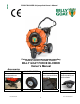
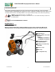
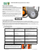
FORCE BLOWER Self-propelled Owner’s Manual Patent #6,253,416 and other patents pending F902SPS, F902SPH, F1302SPH, F1802SPV BILLY GOAT FORCE BLOWER Owner's Manual Accessories HOLD DOWN KIT To secure blower for transportation on trailer floors. P/N 440120 Part No 440314 SOLID FRONT TIRE Solid flat-free front tire. PARKING BRAKE Effective and Easy to use to prevent blower from rolling. CASTER KIT For greater maneuverability on hard surfaces.
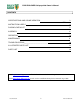
FORCE BLOWER Self-propelled Owner’s Manual CONTENTS SPECIFICATIONS AND SOUND/VIBRATION ___ 3 INSTRUCTION LABELS 4 PACKING CHECKLIST 5 ASSEMBLY 6 OPERATION _ 7-8 MAINTENANCE 9 TROUBLESHOOTING___________________________ 10 ILLUSTRATED PARTS LIST 11 PARTS LIST 12 Go to http://www.billygoat.com for French-Canadian translations of the product manuals. Visitez http://www.billygoat.
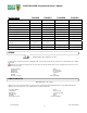
FORCE BLOWER Self-propelled Owner’s Manual Specifications F902SPS F902SPH F1302SPH F1802SPV 9.0 HP (6.6kW) 9.0 HP (6.6kW) 13.0 HP (9.6kW) 18 HP (13.42kW) Engine: Model EX270D50021 GX270K1QA2 GX390K1QAA2 3564420224E9 Engine: Type SUBARU OHC HONDA OHV HONDA OHV B & S VANGUARD Engine: Fuel Capacity 6.4 qt. (6.1L) 6.3 qt. (6.0L) 6.5 qt. (6.1L) 9 qt. (8.52L) Engine: Oil Capacity 1.05 qt. (1.0L) 1.16 qt. (1.1L) 1.16 qt. (1.1L) 1.75 qt. (1.
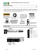
FORCE BLOWER Self-propelled Owner’s Manual INSTRUCTION LABELS The labels shown below were installed on your BILLY GOAT ® FORCE Blower. If any labels are damaged or missing, replace them before operating this equipment. Item numbers from the Illustrated Parts List and part numbers are provided for convenience in ordering replacement labels. The correct position for each label may be determined by referring to the Figure and Item numbers shown.
FORCE BLOWER Self-propelled Owner’s Manual PACKING CHECKLIST These items should be included in your carton. If any of these parts are missing, contact your dealer. Your BILLY GOAT ® FORCE Blower was shipped in one carton, completely assembled except for the Upper Handle Assembly and Front Diverter. Mounting hardware for the Upper Handle Assembly can be found in the parts bag. READ all safety instructions before assembling unit.
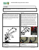
FORCE BLOWER Self-propelled Owner’s Manual ASSEMBLY 1.Follow the steps in figures A and B, then securely tighten all hardware shown. 2.Connect spark plug wire. Figure A Figure B The hardware for attaching the upper handle to the lower is in the parts bag. Install upper handle (item 30), to preassembled lower handle (item 28) by sliding the upper over and down the outside of the lower handle. Using bolt (items #36 and 123), washers (item #10) & lock nut (item #11) to install upper handle to lower handle.
FORCE BLOWER Self-propelled Owner’s Manual OPERATION DRIVE LEVER: To engage the clutch for forward motion, simply hold down the clutch lever with your left hand while the engine is running, this will cause the drive to engage and the machine will proceed to move forward. Caution: It is not recommended to “feather” the drive. The drive lever should be either fully engaged or fully disengaged. Failure to do so can cause premature failure of the cone clutch in the transmission.
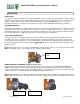
FORCE BLOWER Self-propelled Owner’s Manual MAINTENANCE Periodic maintenance should be performed at the following intervals: Maintenance Operation Inspect for worn or damaged parts. Every Use Daily or Every 5 Hours Every 50 Hours Every 100-150 Hours z z Check for excessive vibration Check belt/chain tightness Every 25 Hours z z Oil drive chain z Inspect Impeller for cracks or damage z Inspect for loose parts. IMPELLER REMOVAL 1. Wait for engine to cool and disconnect spark plug. 2.
FORCE BLOWER Self-propelled Owner’s Manual DRIVE CHAIN REPLACEMENT 1. Wait for engine to cool and disconnect spark plug. 2. Place a block of wood, or another object that will support and steady the unit under the axle on the side of the machine you will be working on. 3. Remove the two screws (item 103) holding the chain guard (item 104) and then remove the chain guard. 4. Loosen the two nuts (item 98) holding the bearing (item 97). 5.
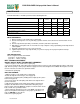
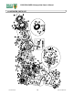
FORCE BLOWER Self-propelled Owner’s Manual ILLUSTRATED PARTS LIST Part No 440314 10 Form No F060811E
FORCE BLOWER Self-propelled Owner’s Manual PARTS LIST F1302SPH F902SPH F902SPS F1802SPV ITEM NO. DESCRIPTION PART NUMBER QTY. PART NUMBER QTY. PART NUMBER QTY.
FORCE BLOWER Self-propelled Owner’s Manual PARTS LIST ITEM NO. 65 66 67 68 69 70 71 72 73 74 75 76 77 78 81 82 83 84 85 86 87 88 89 90 91 92 93 94 96 97 99 100 101 102 103 104 105 108 109 111 113 114 115 117 118 119 120 121 122 123 125 F1302SPH F902SPH F902SPS F1802SPV DESCRIPTION PART NUMBER QTY. PART NUMBER QTY. PART NUMBER QTY. PART NUMBER CABLE ASSY 440117 1 440117 1 440117 1 440117 DIVERTER PIVOT ADAPTOR 440121 1 440121 1 440121 1 440121 SPRING EXTENSION 0.468 X 5.