FORCE 6 BLOWER Owner’s Manual Patent #6,253,416 and other patents pending F601S BILLY GOAT FORCE BLOWER Owner's Manual ACCESSORIES FRONT AIR DIRECTOR Simple to attach, allowing air to be directed forward.
FORCE 6 BLOWER Owner’s Manual ABOUT THIS MANUAL THANK YOU for purchasing a BILLY GOAT ® FORCE Blower. Your new machine has been carefully designed and manufactured to provide years of reliable and productive service. This manual provides complete operating and maintenance instructions that will help to maintain your FORCE Blower in top running order. Read this manual carefully before assembling, operating, or servicing your equipment.
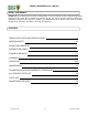
FORCE 6 BLOWER Owner’s Manual SERIAL PLATE DATA Record the model number, serial number, date of purchase, and where purchased. Purchase Date: Purchased From: Specifications F601S Engine: HP 6.0 HP (4.7kW) Engine: Model EX17D50012 Engine: Type SUBARU Engine: Fuel Capacity 3.8 qt.(3.6 L) Engine: Oil Capacity 0.63 qt.(0.60 L) Total Unit Weight: 76# (34.5 kg) Overall Length: 43.5"(1.1m) Overall Width 22” (0.56m) Overall Height 45" (1.
FORCE 6 BLOWER Owner’s Manual GENERAL SAFETY INSTRUCTIONS and SYMBOLS The safety symbols shown below are used throughout this manual. You should become familiar with them before assembling, operating, or servicing this equipment. This symbol indicates important information that will prevent injury to yourself or others. This symbol indicates ear protection is recommended when operating this equipment. This symbol indicates eye protection is recommended when operating this equipment.
FORCE 6 BLOWER Owner’s Manual DO NOT run this equipment indoors or in any poorly ventilated area. Refueling outdoors is recommended. DO NOT refuel this equipment while the engine is running. Allow engine to cool for at least two minutes before refueling. DO NOT store gasoline near an open flame. DO NOT remove gas cap while engine is running. DO NOT start or operate engine if strong odor of gasoline is present. DO NOT start or operate engine if gasoline is spilled.
FORCE 6 BLOWER Owner’s Manual SOUND SOUND LEVEL 89 Db(a) at Operators Position Sound tests were conducted in accordance with 2000/14/EC, as well as ISO 11094, and were performed on 8-32007 under the conditions listed below. Sound power level listed is the highest value for any model covered in this manual. Please refer to serial plate on the unit for the sound power level for your model. General Conditions: Temperature: Wind Speed: Wind Direction: Humidity: Barometric Pressure: Sunny 87.8oF (31.1oC) 1.
FORCE 6 BLOWER Owner’s Manual INSTRUCTION LABELS The labels shown below were installed on your BILLY GOAT ® FORCE Blower. If any labels are damaged or missing, replace them before operating this equipment. Item numbers from the Illustrated Parts List and part numbers are provided for convenience in ordering replacement labels. The correct position for each label may be determined by referring to the Figure and Item numbers shown.
FORCE 6 BLOWER Owner’s Manual PACKING CHECKLIST These items should be included in your carton. If any of these parts are missing, contact your dealer. Your BILLY GOAT ® FORCE Blower was shipped in one carton, completely assembled except for the Upper Handle Assembly and Front Diverter. Mounting hardware for the Upper Handle Assembly can be found on the lower handle. READ all safety instructions before assembling unit.
FORCE 6 BLOWER Owner’s Manual ASSEMBLY 1.Follow the steps in figures A and B, then securely tighten all hardware shown. 2.Connect spark plug wire. Figure A Figure B The hardware for attaching the upper handle to the lower can be found on the lower handle. Install upper handle (item 24), to preassembled lower handles (item 25 & 26) by sliding the upper over and down the inside of the lower handle. Using bolt (item #12), washers (item #10) & lock nut (item #11) to install upper handle to lower handle.
FORCE 6 BLOWER Owner’s Manual OPERATION Like all mechanical tools, reasonable care must be used when operating machine. Inspect machine work area and machine before operating. Make sure that all operators of this equipment are trained in general machine use and safety. PUT OIL IN ENGINE BEFORE STARTING STARTING ENGINE: See engine manufacturer’s instructions for type and amount of oil and gasoline used. Engine must be level when checking and filling oil and gasoline.
FORCE 6 BLOWER Owner’s Manual ADJUSTING AIR DIRECTOR To adjust air direction, squeeze Aim-N-ShootTM control lever. When you want to blow debris at the same angle for an extended period, choose a suitable position and use the finger controlled push button lock to lock the cone in position. For operations that do not require the use of the Aim-N-ShootTM feature the manual adjustment knob, pictured below, can be used to permanently lock the cone into position.
FORCE 6 BLOWER Owner’s Manual MAINTENANCE PERIODIC MAINTENANCE Periodic maintenance should be performed at the following intervals: Maintenance Operation Inspect for worn or damaged parts. Every Use Daily or Every 5 Hours Every 25 Hours Every 50 Hours Every 100-150 Hours z z Check for excessive vibration z Inspect Impeller for cracks or damage z Inspect for loose parts. IMPELLER REMOVAL 1. Wait for engine to cool and disconnect spark plug. 2.
FORCE 6 BLOWER Owner’s Manual TROUBLESHOOTING Problem Abnorm al vibration. Engine will not start. Engine is locked, will not pull over. TM lever sticking Aim -N-Shoot Possible Cause · Loose or out of balance im peller. · Debris in im peller. · Loose engine. Solution · Check im peller and replace if required. · Clear debris with com pressed air or a backpack blower (see below pictures).* · Check engine. · Engine not in full choke position. · Out of gasoline or bad, old gasoline. · Check choke position.
FORCE 6 BLOWER Owner’s Manual ILLUSTRATED PARTS LIST Part No 441161 14 Form No F113007B
FORCE 6 BLOWER Owner’s Manual PARTS LIST F601S ITEM NO. DESCRIPTION PART NUMBER QTY. ENGINE 6 HP HORZ SUBARU 350307 1 2 BASE ENGINE WA 441151-S 1 3 SCREW PLASTITE #8-16 X 3/4" HWH 441155 10 4 PLATE REINFORCE HOUSING 441102 2 5 HOUSING FRONT MOLDED 441101-1-S 1 6 HOUSING BACK MOLDED 441101-2 1 7 WASHER LOCK 5/16 ST MED 8177011 5 8 SCREW CAP 3/8-16X1 1/2 ZP 400164 4 9 ROD HAND STOP 441154 1 10 WASHER 5/16 FLATWASHER Z/P 8171003 10 11 NYLON INSERT LOCKNUT 5/16-18 8160002 6 12 SCREWCAP 5/16-18 X 1.
FORCE 6 BLOWER Owner’s Manual MAINTENANCE RECORD Date Part No 441161 Service Performed 16 Form No F113007B