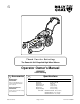
TM Thank You for Selecting The Powerful Self-Propelled High Wheel Mower Operator Owner's Manual HW650SP Patent Pending 2 Accessories 3 Specifications Mulching Kit P/N 510202 Reduces lawn clippings to fine nutrient-rich particles that filter down to the soil. Grass Catcher Kit P/N 510223 Easily convert your mower to bag grass and leaves. Part No. 510153 HW650SP Engine: HP Engine:Type Engine: Fuel cap. Engine: Oil Cap. Weight: Unit Weight: Shipping UNIT SIZE: Page 1 of 12 6.5 HP (4.
5 IN THE INTEREST OF SAFETY BEFORE STARTING ENGINE, READ AND UNDERSTAND THE “ENTIRE OPERATOR'S MANUAL & ENGINE MANUAL.” THIS SYMBOL MEANS WARNING OR CAUTION. DEATH, PERSONAL INJURY AND/OR PROPERTY DAMAGE MAY OCCUR UNLESS INSTRUCTIONS ARE FOLLOWED CAREFULLY. WARNING: The Engine Exhaust from this product contains chemicals known to the State of California to cause cancer, birth defects or other reproductive harm. WARNING: DO NOT 12. DO NOT run engine at excessive speeds.
9 GENERAL SAFETY For your safety and the safety of others, these directions should be followed: Do not operate this machine without first reading owner's manual and engine manufacturer's manual. Use of Ear Protection is recommended while operating this machine. Use of Eye and Breathing protection is recommended when using this machine. This cutting machine is capable of amputating hands and feet and throwing objects.
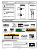
11 12 ASSEMBLY 13 CONTROLS LITERATURE ASSY P/N 500263 Throttle Control Literature Checklist Read all safety and operating instructions before assembling or starting this unit. FIXED THROTTLE Engine speed is factory set. Check Owner's Manual Owner's Manual PUT OIL IN ENGINE BEFORE STARTING. Speed Control 510153 Push foward for faster speed, Pull back for slower speed SPEED 3 DISCONNECT SPARK PLUG WIRE BEFORE ASSEMBLING UNIT.
OPERATION 16 INTENDED USE: This unit is mainly designed for cutting grass. Some overgrown weeds, and taller grass may also be cut. Be sure to inspect work area and machine before operating. Make sure that all operators of this equipment are trained in general machine use and safety. 16.2 CAUTION: The mower blade will be rotating whenever engine is running. Like all mechanical tools, reasonable care must be used when operating machine. Do not operate unit in areas where bystanders may be present.
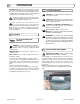
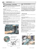
16 16.4 OPERATION continued PROPULSION 16.5 This unit is self-propelled, and is controlled by an operator presence control. To engage the wheel drive, push forward on the bail (back of the handle) and squeeze it against operator's handle. The drive is disengaged by releasing this bail.(See Fig. 2) FRONT CASTER LOCK Front caster can be locked with a remote located on the rear of the machine for mowing on hillsides (fIg. 4 & 5). WARNING! Never mow on any slope greater than 15 degrees.
16 OPERATION 16.5 continued HILLSIDE MOWING STORAGE 16.7 Never store engine indoors or in enclosed poorly ventilated areas with fuel in tank, where fuel fumes may reach an open flame, spark or pilot light, as on a furnace, water heater, clothes dryer or other gas appliance. If engine is to be unused for 30 days or more, prepare as follows: HILL Be sure engine is cool. Do not smoke.
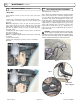
17 MAINTENANCE 17.1 continued BLADE REMOVAL / SHARPENING 17.2 NOTE: When sharpening the blade it is a good idea to check the balance of the blade. A properly balanced blade will increase life of the bearings and other components. Tools required: 3/8 inch socket, 5/8 inch socket, torque wrench, blade block. 1. Disconnect spark plug wire. 2. Remove 5 screws (item 76) then remove belt guard (19). 3. Set the unit on its side to allow access to both pulley and the blade.
17 MAINTENANCE 17.2 continued BELT REPLACEMENT continued 17.3 SELF PROPELLED DRIVE ADJUSTMENT Tools required: two 1/2 wrenches. Drive Belt Tools required: 3/8 inch socket, 1/2 inch socket, 3/8" torque wrench. 1. Follow steps 1 through 5 above to remove the blade drive belt. 2. Set the unit on its side to allow access to both pulley and the blade. Note: When tipping the unit on its side, keep the air cleaner side of engine up.
1 1 79 2 3 4 93 5 6 71 62 76 19 5 71 13 12 96 98 14 76 8 96 100 9 11 78 15 64 10 16 95 97 72 71 21 95 53 70 97 95 71 89 26 86 27 28 25 97 29 97 57 84 23 67 55 30 75 33 89 71 31 88 59 86 81 71 74 23 97 35 47 22 54 106 83 70 108 18 17 105 24 71 65 65 85 107 20 96 110 109 92 65 82 7 87 48 63 112 73 32 99 77 34 68 72 36 71 37 103 65 38 111 71 102 46 104 45 40 41 56 96 50 94 61 90 69 85 60 42 40 58 94 51 49
19 Item No. 1 2 3 4 5 6 7 8 9 10 11 12 13 14 15 16 17 18 19 20 21 22 23 24 25 26 27 28 29 30 31 32 33 34 35 36 37 38 39 40 41 42 43 44 45 46 47 48 49 50 51 52 53 54 55 56 57 PARTS LIST Description ROD BAIL DRIVE WA ROD BAIL ENGINE WA CABLE ENGINE BRAKE CABLE CLUTCH DRIVE HW KNOB WING 5/16” NC BLACK CONTROL SHIFT 3 SPEED HANDLE UPPER HW GUIDE ROPE ENGINE 6.
20 TROUBLESHOOTING Before Requesting Service Review These Suggestions NOTE: For repairs beond the minor adjustments listed below, contact your nearest authorized service dealer. Problem Possible Cause Solution The engine will not start 1. Operator presence control bail is not engaged. 2. Engine not properly primed. 3. Out of gasoline or bad or old gasoline. 4. Spark plug wire disconnected. 5. Dirty air cleaner. 6. Blade is trying to cut grass while starting. 1.