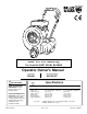
Thank You for S e l e c t i n gg The Powerful QUIET BLOW® BLOWER Operator Owner's Manual 2 ACCESSORIES Push Model Self Propelled Model QB1601 QB1601SP Specifications 3 GUST ADJUSTER KIT P/N 400685 Increases blowing distance and blowing control. DEFLECTOR REMOTE KIT P/N 400686 Adds operator remote control for quickly changing between side and forward direction blowing. (Standard on Self Propelled models). Part No. 430149 Engine: HP(kW) Engine: Type Engine: Fuel cap. Engine: Oil Cap.
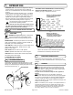
IN THE INTEREST OF SAFETY 5 BEFORE STARTING ENGINE, READ AND UNDERSTAND THE “ENTIRE OPERATOR'S MANUAL & ENGINE MANUAL.” THIS SYMBOL MEANS WARNING OR CAUTION. DEATH, PERSONAL INJURY AND/OR PROPERTY DAMAGE MAY OCCUR UNLESS INSTRUCTIONS ARE FOLLOWED CAREFULLY. WARNING: The Engine Exhaust from this product contains chemicals known to the State of California to cause cancer, birth defects or other reproductive harm. WARNING: DO NOT 13.
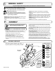
GENERAL SAFETY 9 For your safety and the safety of others, these directions should be followed: Do not operate this machine without first reading owner's manual and engine manufacturer's manual. Use of Ear Protection is recommended while operating this machine. Use of Eye and breathing protection is recommended when using this machine, especially in dry and dusty conditions. ·DO NOT place hands or feet inside air intake opening, near exhaust outlet or near any moving parts.
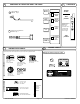
PARTS BAG & LITERATURE ASSY P/N 400983 12 13 Clamp Cable 1" 156 900813 Qty. 4 Throttle Control Literature Checklist Owner's Manual Check CONTROLS Owner's Manual 430149 Literature QB1601 Accessories Check 10 EU Declaration of Conformity & EU Distributor List 14 15 INSTRUCTION LABELS These labels should be included on your Blower. If any of these labels are damaged, replace them before putting this equipment into operation.
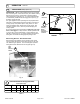
10 ASSEMBLY Exhaust door control Stop switch bracket Jam nut Mounting hardware Handle mounting hardware Stop switch grounding wire Fig. 7 Fig. 6 Exhaust door Exhaust Door pivot rod Control Jam nut Clutch Brake Clutch cable Deflector screws Brake cable Jam nut Fig. 8 Part No. 430149 Fig. 9 Page 5 of 16 Form No.
16 OPERATION INTENDED USE: This machine is designed for cleaning outdoor surfaces, where the debris can be effectively blown into a consolidated area for convenient pickup and removal. Do not operate if excessive vibration occurs. If excessive vibration occurs, shut engine off immediately and check for damaged or worn impeller, loose impeller bolt, loose impeller key, loose engine or lodged foreign objects. Note: See parts list for proper impeller bolt torque specifications.
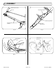
OPERATION 16 continued PROPULSION self propelled only 16.6 PROPULSION: QB1601 self-propelled blowers are equipped with 5 forward gears, neutral and reverse. (see TABLE 1 below) With the engine running, and the bail in released position select desired drive gear.(see Fig. 4) Pull bail against handle to automatically release brake and engage drive (see Fig. 5). Smoothly engage the bail. Use good judgement when operating the self propelled drive.
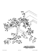
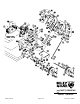
18 PARTS DRAWING QB1601, QB1601SP Part No. 430149 Page 8 of 16 Form No.
18 PARTS DRAWING QB1601, QB1601SP Part No. 430149 Page 9 of 16 Form No.
Item No. PARTS Continued LIST Description QB1601 QTY QB1601SP QTY 1 2 3 4 5 6 7 8 9 10 11 12 ENGINE 16 HP VANGUARD 811057 1 811057 1 GRILL SCROLL W. A. FRAME FRONT WHEEL W.A.
Item No. 100 101 102 103 104 105 106 107 108 109 110 111 112 113 114 115 116 117 118 119 120 121 122 123 124 125 126 127 128 129 130 131 132 133 134 135 136 137 138 139 140 141 142 143 144 145 146 147 148 149 150 151 152 153 154 155 156 157 158 159 160 161 162 163 164 165 166 167 168 169 Part No.
* Denotes standard hardware item that may be purchased locally. Part No. 430149 19 170 171 172 173 174 175 176 177 178 PARTS Item Continued LIST No. QB1601 Description QTY QB1601SP QTY SCREW CAP 5/16-18 x 1” GR. 5 400912 4 400912 4 LABEL WARNING OPEI LABEL DANGER FLYING MATERIAL LABEL EAR EYE BREATHING LABEL DO NOT FILL WHEN ENGINE IS HOT SCREW MACH.
17 MAINTENANCE Use only a qualified mechanic for any adjustments, disassembly or any kind of repair . WARNING: TO AVOID PERSONAL INJURY, ALWAYS TURN MACHINE OFF, MAKE SURE ALL MOVING PARTS COME TO A COMPLETE STOP. DISCONNECT SPARK PLUG WIRE BEFORE SERVICING UNIT. 17.1 IMPELLER REMOVAL continued 12. (Self propelled models only) When impeller is installed, slide belt into drive pulley. 13. Reattach front intake plate and front wheel bracket in reverse order of removal. 14.
17 MAINTENANCE continued Clear intake screens on housing and engine throughout use. Inspect machine for loose bolts before starting engine. Lubrication: Using S.A.E. 30 weight oil or equivalent. See maintenance schedule. Chain: See SP section below. Lower Control Ends: Oil moving parts, such as bail, and deflector door pivots. Grease: Front wheel, and Caster(SP only). Tire air pressure: Check at regular intervals & maintain: Low tire pressure will make unit hard to push and turn. Front tire at 30 psi.
17.3 DRIVE continued Chain tensioner bolt Chain tensioner bolt Jam nut Jam nut Bearing Bolt Bearing Bolt Fig. 11 17.5 STOP SWITCH & WIRING DIAGRAM Spark Plug Stop Switch (Item 118) on engine (push) or on handle (SP) Spark Plug Fig. 12 Part No. 430149 Page 15 of 16 Form No.
20 TROUBLESHOOTING Before Requesting Service Review These Suggestions Problem Possible Cause Solution Poor air performance Air intake or exhaust clogged. Clear clog. Machine is difficult to maneuver. Low tire air pressure. Inflate front and rear tires to correct pressure. (See tire pressures on page 14.) Abnormal vibration Loose or out of balance impeller or loose engine. Check impeller and replace if required. Check Engine. Engine will not start Stop switches off.