THANK YOU FOR SELECTING THE POWERFUL BILLY GOAT SOD CUTTER OPERATING AND SAFETY INSTRUCTIONS MODEL: SC120H SPECIFICATIONS ENGINE: H.P. ENGINE: TYPE ENGINE: CAPACITY ENGINE: FUEL CAP. ENGINE: OIL CAP. WEIGHT: UNIT MAX. ENGINE OPERATING SLOPE: UNIT SIZE: 5.5 (4.1 KW) Gasoline, HONDA GX 160 K1 5.5 hp (4.0 kW) 3.0 qt. (2.84L) 0.66 qt. (0.6 L) 160.9 # (73 Kg) 15° 30.7 in x 16.5 in x 24.0 in (0.78 m x 0.42 m x 0.
OPERATING AND SAFETY INSTRUCTIONS SOD CUTTER MODEL-SC120H FOREWORD This machine may only be utilized for the purpose for which it was designed, i.e. agricultural use, for the cutting of shoots, grass and brushwood. Any other use other than that stated, not covered or deducible from this Manual and the enclosed Engine Manual is "PROHIBITED".
Contents of the SOD CUTTER Manual 1. 2. 3. 4. 5. 6. 7. 8. 9. 10. 11. 12. 13. 14. 15. 16. 17. 18. 19. 20. 21.
2. NOTICES ON THE MACHINE In this Manual all safety information appears in special boxes headed "WARNING". WARNING This heading is used to draw the user's attention to hazardous areas or moving parts of the machine. It is also used in instances where failure to comply with the instructions given may result in injury to persons and animals or damage to property.
370302 – Label Controls Instruction, Qty. 1 370300 – Label Instructions, Qty. 1 3.
ENGINE : Gasoline, HONDA GX 160 K1 ENGINE CAPACITY : 5.5 hp (4.0 kW) CUTTING WIDTH : 12” (30 cm) CUTTING HEIGHT : adjustable up to 35 mm SPEED GEARS : 1 forward gear - 1 reverse gear TRANSMISSION : mechanical GEARS : in oil bath START : recoil HEIGHT-ADJUSTABLE HANDLEBARS TIRES : front tires = GARDEN 3.00-4 rear tires = GARDEN 4.10/3.50-4 DIMENSIONS L x W x H (mm) : 780 x 420 x 610 mm WEIGHT (kg) : 73 ACOUSTIC PRESSURE, measured according to DIR.
All material is carefully checked by the manufacturer before shipping. The sod cutter is delivered in a cardboard box with the handlebars and end part of the cutting height adjustment lever disassembled. Upon receipt of the machine make sure that it has not been damaged during transit and that the packaging has not been tampered or any parts removed. Report any damage or missing parts immediately to the carrier and the manufacturer with photographic documentation.
5.
6. CONTROL AND ADJUSTMENTS A) BLADE CLUTCH CONTROL LEVER This is used to engage and disengage the blade movement. Lowering the lever engages the clutch and releasing it disengages the clutch. WARNING The blade will continue to move if the engine is running and the blade clutch is engaged, regardless of the position of the forward clutch. B) ACCELERATOR CONTROL LEVER This is used to adjust the number of engine revolutions according to the operations to be carried out.
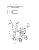
D) CUTTING HEIGHT ADJUSTMENT LEVER This lever serves to adjust the cutting height according to the type of terrain and the thickness of the turf to be cut. (Fig.2 Ref. A) F) COVER The cover ( Fig. 1, ref. F) prevents any contact with the moving parts of the machine. Use of the machine without the said cover is strictly prohibited.
6. ASSEMBLY INSTRUCTIONS FOR THE HANDLEBARS AND END PART OF THE CUTTING HEIGHT ADJUSTMENT LEVER The sod cutter is delivered with the handlebars and the end part of the cutting height adjustment lever disassembled. Remove the cardboard packaging (to be disposed of in an appropriate manner, in accordance with current regulations in force). To assemble proceed as follows : -Lift the handlebar (Fig. 3 Rif. C) and insert it in the supports shown in Fig. 3 rif. E.
8. SAFETY INFORMATION Before using the sod cutter it is essential that the operator has understood the warnings, do's and don'ts and precautionary measures given in this manual and in the engine manual: the prevention of injury to the operator, third parties, animals or objects directly depends on observance of these instructions. A) GENERAL INSTRUCTIONS ! Use of the sod cutter for purposes other than those envisaged is strictly prohibited.
! Supervise the clothing of personnel operating the machine: a long-sleeved jacket with close-fitting cuffs, long, close-fitting trousers, heavy-duty footwear, and a protective cap or helmet should be worn. Avoid wearing loose-tailed clothing, unbuttoned jackets or torn, undone or partially zipped up items to prevent them from being caught up in the moving parts. ! Safety goggles and ear protection devices must be worn. Safety gloves must also be worn during machine operation and maintenance.
WARNING. When working in a stony or obstacle-riddled area try to remove as many objects as possible before commencing cutting. Then work at a greater cutting height than usual. WARNING Stones and other objects may be thrown outwards in direction of the operator or of other persons in the vicinity. Keep at a safe distance from persons, animals and objects.
9.TRANSPORTATION OF THE MACHINE LOADING AND UNLOADING FROM A VEHICLE ! ! ! For transportation it is preferable to use a vehicle with an open bed. Choose firm, flat ground. Switch off the vehicle's ignition, put into reverse gear, pull on the hand brake and block the tires with chocks to prevent accidental movement of the vehicle.
10. DESCRIPTION OF THE SAFETY AND GUARD SYSTEMS WARNING The safety devices must never be tampered with. It is necessary to understand how they work and safeguard their efficiency and correct operation. In the instance of doubt, problems or malfunction contact your dealer. FORWARD CONTROL AND BLADE MOVEMENT LEVERS When released both of these levers instantly disengage the transmission connected to them. In this way they act as safety devices.
12. STARTING AND DRIVING THE SOD CUTTER The machine can be switched on once all the aforementioned preliminary operations have been carried out. Place the feed cock in the OPEN position (direction shown by the arrow) (fig. 4) Bring the choke to the CLOSED position for a cold start (direction shown by the arrow, Fig. 4a) Set the accelerator lever at the minimum position. Grip the engine pull lead handle (fig.
DRIVING THE MACHINE WARNING. When using the machine for the first time it is advisable to get the feel of it by executing manoeuvres on flat ground free of foreign objects. After switching on the engine following the instructions given in the previous paragraph: 1. Move the gear lever (fig. 2, ref. C) to the FORWARD position Warning. If the gear engages with difficulty, partially engage the clutch for an instant before trying to engage the gear again. 2.
14. - - CHECKS Adjust the belt and cable control tension after the first few working hours to compensate initial loosening. Briefly operate all the machine's components to detect any abnormal noises or overheating. During the initial running in period avoid heavy-duty usage to encourage proper settling of the mechanical parts. Never neglect maintenance operations after work and carry out all prescribed checks regularly. A) TIRE PRESSURE Regularly check the tire pressure.
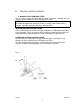
C)BELT REPLACEMENT AND ADJUSTMENT Switch off the engine and disconnect the spark plug wire before carrying out any maintenance or repair work on the machine. If a belt is worn or breaks it should be replaced as follows: - remove the metal guard ( fig. 6 ref. A), by unscrewing and taking out the screws shown in figure 6 ref. B and C. C1)BLADE BELT Disconnect the connecting rod (Fig. 7 Ref. B) by removing the nut and loosening the screw that secure it to the arm (Fig. 7 Ref.
Fig. 6 Fig.
Fig. 8 Fig.
D) SERVICE BRAKE CONTROL LEVER The service brake (Fig. 9 Ref. A) is connected to the forward control lever (Fig. 1 Ref. C). With the forward control lever released and the brake engaged ensure that there is play of approximately 2 or 3 mm between the adjustment screw and the brake cable (Fig. 9 Ref B and C) WARNING. If there is no such play restore it immediately since the brake will not stop the machine once the forward control lever is released.
FIG. 10 15. MAINTENANCE AND STORAGE ! ! ! ! ! ! ! ! ! ! ! ! All operations on the machine must be carried out exclusively by authorized personnel. Always switch off the engine when checking, adjusting or servicing the machine. Allow the machine to cool down before inspection. The cover ( Fig. 1 ref. F) must always be correctly installed and intact. If it becomes damaged, have it repaired before the machine is used again. Make sure that all the guards of rotating and moving parts are in place.
! ! After use store the machine in a place where fuel vapours cannot reach a naked flame or sparks. In the instance of a long period of non-use, drain the fuel tank completely. Use of the machine does not require specific lighting. However, the recommended minimum amount of light (e.g. 200 lux) to be able to read the notices on the machine and to operate it without running risks caused by poor light. CHECKING AND REPLACING THE TRANSMISSION OIL.
16. CLEANING THE MACHINE Proceed in the following order: - - - Switch off the engine and disconnect the spark plug wire; Clean the engine and the outside of the machine with a cloth soaked in a little oil. Clean all parts of the machine, particularly the starting unit, air filter, exhaust and carburetor. It is advisable to follow the instructions given in the engine manual. Clean the inside of the belt guard (fig. 1, ref. F) with a blast of compressed air. To clean the blade (fig. 1 ref.
18. DECOMMISSIONING AND SCRAPPING After the working life of the sod cutter the user must have it dismantled and its components removed as per EEC directives or in accordance with current legislation in force in his country, taking particular care over the dismantling of the following materials of environmental impact: - plastic parts - rubber parts - coated electric wiring - petrol engine - metal parts - toxic substances 19.
21. TROUBLESHOOTING The following table illustrates some problems which may arise during operation. FAULT CAUSE ACTION 1. Adjust the belt tension Belt slips 1. Belt tension inadequate 2. Too great a working depth 2. Reduce the working depth 3. Replace belt 3. Belt worn 1. Replace belt Machine vibrates excessively 1. Belt damaged 2. Replace blade 2. Blade bent or broken Engine overloads during work 1. Engine speed too low. operations 2. Blade worn 3. Forward speed too high 1. Accelerate to maximum 2.
ENGINE FAULT Engine sluggish at switch on CAUSE MEASURES TO BE TAKEN 1. Accelerator not in start-up 1. Move the accelerator to the intermediate position position 2. Close the choke when cold. 2. Choke not closed 3. Check the fuel tank and remove any water or sedi3. Petrol does not arrive ment. 4. Air bubbles or water inside 4. Make sure that the feed cock is open. the petrol lines 5. Thick oil prevents rotation 5. Check the lines and bands. Repair or replace if damaged 6. Winding or start mecha6.
NOTES _________________________________________________________________________ _________________________________________________________________________ _________________________________________________________________________ _________________________________________________________________________ _________________________________________________________________________ _________________________________________________________________________ ______________________________________________________________
370310 F112003A 31
PARTS LIST 1/6 1 2 3 4 5 6 7 8 9 10 11 12 13 14 15 16 17 18 19 20 21 22 23 24 28 29 34 35 36 37 38 39 40 41 42 43 44 47 48 49 50 54 60 62 65 370252 Lever Control (righthand ) 370257 Knob 370253 Lever Tightener (lefthand) 370178 Screw M6x55 UNI 5931 370107 Nut Lock M6 H6 370255 Lever Hand Accelerator 370112 Washer Flat M6 370254 Cable Accelerator 370148 Nut Lock M6 H8 370281 Screwcap M10x 20 370256 Clamp Accelerator 370186 Spring guide 370143 Spring 10x25 C X F 370187 Cable guide 370274 Handle 370243 Lever
PARTS LIST 1/6 CONTINUED 72 112 113 114 115 370102 Nut 8 H 6.
PARTS LIST 2/6 21 23 24 28 30 31 32 33 38 41 44 48 55 56 57 59 63 64 66 70 71 72 73 74 79 84 85 86 87 88 89 90 91 370110 Washer Flat M8 370259 Fork 03216055 370260 Clip Fork 370146 Nut M10 370147 Screwcap M10x50 P.F. 370145 Washer wave M10 370228 Support Handle 370247 Nut Special for handle support 370125 Nut Lock M8 370118 Screwcap M8x25 370130 Screwcap M8x20 370112 Washer Flat M6 370236 Connection tie-rod 370151 Pin Roll M30x2.
PARTS LIST 3/6 5 7 25 26 27 45 46 49 51 52 53 58 61 67 68 69 75 76 77 78 80 81 82 83 92 93 94 95 96 97 98 99 100 101 102 103 104 105 106 107 108 109 110 111 370107 Nut Lock M6 H6 370112 Washer Flat M6 370136 Nut M8 H5 370272 Screw Stud M8x20 UNI 5911 370224 Arm Control Blade (Righthand) 370157 Key 8x7x25 370177 Screw Allen M6 x 25 370128 Screwcap M6 x 14 370211 Pulley for shaft with eccentrics 370150 Nut M12 370197 Belt Short XDV48/290 370124 Washer Flat M12x24 370287 Screw Special 370138 Bearing 17x40x12
PARTS LIST 4/6 1 2 3 4 5 6 7 8 9 10 11 12 13 14 15 16 17 52 64 65 370126 Screwcap M8x16 370110 Washer Flat M8 370194 Rim Rear wheel 370277 Tube Inner Rear Wheel 370278 Tire Rear 370195 Hub wheel 370158 Pin Elastic 10x40 370288 Cover Dust 370289 Felt protection 370305 Ring Seal 25 X 52 X 7 370114 Ring Snap Internal 152 370131 Bearing 25x52x15 6205 370199 Gear Reduction-crown 370180 Dowel M8x14 370196 Axle Rear 370142 Shim adjustment 25x35x1 370290 Seeger E25 370136 Nut M8 H5 370170 Key 7x8x35 370121 Shim Ad
PARTS LIST 5/6 18 19 20 370182 Plastic knob Ø 12 370162 Cap Plastic 370163 Washer Fiber 1 1 1 21 22 370159 Screw Allen M 8 x 16 370226 Lever Engage-disengage 4 1 23 24 25 370264 Spring Gear Fork 6x25 370160 Ball 370233 Fork Engage-disengage 1 1 1 26 27 28 29 30 370161 Casing 370227 Fork pivot 370125 Nut Lock M8 370201 Gear Reverse-pinion 370164 Key 5x5x18 1 1 1 1 1 31 32 33 34 35 36 37 38 39 40 41 42 43 44 45 46 47 48 49 50 51 370139 Bushing PCM 1020 12M 370165 Pin Cylindrical 10x50 370202 Gear
PARTS LIST 5/6 CONTINUED 63 370171 O-ring 108 (8.73 x 1.
PARTS LIST 6/6 1 2 3 4 5 6 7 8 9 10 11 12 13 14 15 16 17 18 19 20 21 22 23 24 25 26 27 28 29 30 31 32 33 34 35 36 37 38 39 40 41 42 43 44 370193 Shim Engine 20x6 370110 Washer Flat M8 370234 Support Engine 370172 Screw TTQST 8x40 370175 Washer Toroidal M24 370125 Nut Lock M8 370126 Screwcap M8x16 370238 Guide Belt No.
PARTS LIST 6/6 CONTINUED 46 47 48 49 50 370263 Spring Accelerator Return 370107 Nut Lock M6 H6 370307 Drum Wire Holder 370297 Nut M6 H4 370308 Screwcap M6 X 18 1 2 1 1 1 45
370310 F112003A 46