Hardware Manual IntelliSense® Manual
IntelliSense® Manual Scope of this Manual This instruction manual supports Bimba standard components only. If special components, including but not limited to serial hubs, power supplies, and drivers, are included based on a customer’s specifications or special request, it is the customer’s responsibility to consult support materials and technical support specific to these special components provided by the third party manufacturers.
IntelliSense® Manual Contents IntelliSense® Operating Modes.................................................................................................................................... 4 Cylinder Monitoring............................................................................................................................................................................4 Pressure / Temperature Monitoring...........................................................................................
IntelliSense® Manual IntelliSense® Operating Modes The IntelliSense® Sensor Interface Module (SIM) can be operated in two modes, Cylinder Monitoring or Pressure / Temperature Monitoring. The general installation and setup for these two modes is the same. The modes differ in the status information that is displayed in the software and on the SIM. Figure 1 lists the information provided in each mode. This manual is focused on using IntelliSense® in the Cylinder Monitoring Mode.
IntelliSense® Manual IntelliSense® Architecture IntelliSense® is designed to be scalable in its implementation. It is easy to go from a single standalone SIM to multiple SIMs on a MODBUS RTU network with remote access using an IntelliSense® Data Gateway. The development of an IntelliSense® installation requires merging of four traditionally disparate sub-systems, Pneumatic, Data, Controls, and Power.
IntelliSense® Manual Power Architecture The IntelliSense® SIM should be connected to a Class 2, limited power source or limited-energy power source. The power supply may supply 11~24 VDC. There are two ways to connect power to the IntelliSense® SIM. Power can be supplied: a. over pin 3 (+) and pin 4 (-) of the 4-pin connector b. using pin 7 (+) and pin 8 (-) of the MODBUS port Using the IntelliSense® Junction Block (ISH-R04) is the preferred method of enabling power for option b.
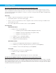
IntelliSense® Manual • Data Logging, Online Monitoring, and MODBUS RTU Network / and PLC discrete inputs All of these setups can support multiple SIM unit setups Basic Monitoring / and PLC Discrete Inputs (appendix drawing 1 and 2) This setup consists of a single SIM unit, power source, and user PC device. Both power options are available. With this setup, the user may connect to the SIM through PC port and visually monitor the current status of the SIM unit and attached pressure system.
IntelliSense® Manual Data Logging and Remote Monitoring / with PLC Discrete Input (appendix drawing 3 and 4) With this setup the user may connect to the SIM unit through the Data Gateway and visually monitor the current status of the SIM unit and attached pressure system. This setup also allows for data logging to be performed and stored in the Data Gateway unit, regardless of a user PC connection. If using the discrete outputs, the SIM must be powered using option b.
IntelliSense® Manual Functionality • Cylinder condition monitoring based on status LEDs on SIM unit • By configuring a MODBUS RTU network between the users’ PLC/HMI (Master Device) and the SIM unit(s) (Slave Device), the user can retrieve desired status values and alerts • User PC connects to SIM for initial configuration and/or real time monitoring of the SIM unit and attached pressure system • Use of EOT outputs with PLC installation and use of power option b List of Components Required Bimba Prod
IntelliSense® Manual Functionality • Cylinder condition monitoring based on status LEDs on SIM unit • By configuring a MODBUS RTU network between the users’ PLC/HMI (Master Device) and the SIM unit(s) (Slave Device), the user can retrieve desired status values and alerts • Data Gateway remains connected for data logging • User PC connects to Data Gateway for initial configuration and/or real time monitoring of the SIM unit and attached pressure system • Use of EOT outputs with PLC installation and
IntelliSense® Manual Sensor Installation Media Compatibility The IntelliSense® pressure sensor is designed to be used with clean dry air. A 5 micron filter should be used. If the sensor is used with other media, it is the user’s responsibility to confirm that it is compatible with the wetted materials in the sensor.
IntelliSense® Manual Sensor Cable 4‐Wire M8F‐M8F (CBL‐IS‐M8‐XX) Sensor 1 Sensor 2 Straight Connector to the SIM Max Torque Finger Tight (2.0 In.lb/0.23Nm) Angled connector to the Sensor Max Torque 3.5 In.lb/0.
IntelliSense® Manual IntelliSense® Data Gateway Installation (optional) Mounting the IntelliSense® Data Gateway The IntelliSense® Gateway is provided with a bracket and clips for mounting to a 35mm DIN rail. The DIN bracket clips can be attached to the bracket so that the Gateway can be mounted edgewise if panel space does not allow the width of the Gateway. Refer to the specifications section for mounted dimensions. Figure 31: Two options for mounting the gateway to a DIN rail.
IntelliSense® Manual The following user interface will then appear: Figure 33: Multi-SIM Monitoring Screen Configure the IntelliSense® Data Gateway Data Gateway Machine Settings Select the Configuration tab on the left of the screen, then the Machine tab on the top. On this page, the following parameters can be entered: Machine name: A name for the gateway Data retention period: The number of days that recorded temperature and pressure should be kept for, disk size permitting.
IntelliSense® Manual Data Gateway Cylinders / SIMs This page is for adding connections to SIMs that the Data Gateway will monitor. For more information, refer to the following section in this document: Add or Configure a SIM on the PC or Gateway. Data Gateway User Administration The Data Gateway has user access control and multiple users can be set up with three levels of access privileges.
IntelliSense® Manual Data Gateway Network Settings The Data Gateway is a TCP/IP v4 device and following network settings can be made to enable communication: Global Server Settings Figure 37: Global network settings Web Port: This defines the TCP port for connecting to IntelliSense®. Unless needed, keep the default value. Base URL: For reference, gives the full URL including port number, to access the current server. Save: All changes must be saved to become effective.
IntelliSense® Manual Figure 38: Wireless Network Settings WiFi When the included wireless adapter is connected to the Data Gateway, the following wireless settings can be entered. Press the save button to make any changes effective. IP Address Assignment DHCP: Configures the Gatway to receive TCP/IP settings from a DHCP server. Static: Allows the user to manually enter the TCP/IP address, subnet mask, gateway and DNS servers.
IntelliSense® Manual Figure 39: Wired network settings Update Gateway Software If connected to the internet, it is possible to update the software on the Data Gateway and download the latest SIM firmware. 1. Select the “About” tab on the left of the screen, then the “Software” tab. 2. Under the Component column, IntelliSense® indicates the Gateway software. The remaining items are for the SIM and sensor firmware. 3.
IntelliSense® Manual Figure 40: IntelliSense® Data Gateway Software Update 19
IntelliSense® Manual SIM Installation DIP Switch Settings The IntelliSense® SIM module has a bank of DIP switches that allow for a variety of different architectural configurations. The DIP switch bank is located under the rear cover of the SIM unit. Before mounting your SIM unit, it is important that the DIP switches are configured to match the installation type being used.
IntelliSense® Manual Network Configuration/MODBUS Settings DIP switches 1-4 should be treated as one switch, either all ON or all OFF. When this set is turned ON, the MODBUS Port and PC Port are internally connected to allow for a daisy chain layout. When OFF (default), the ports are not internally connected. DIP switches 5 and 6 should be treated as one switch, either both ON or both OFF. When this set is turned ON (default), the MODBUS Port is configured for 2-wire RS485.
IntelliSense® Manual DIN Rail Mount - included with the SIM are clips for mounting to 35mm DIN rail. The clips attach to the rear of the SIM back plate with the included #6 screws. When the screws are tightened down, the clips will grip onto the flanges of the DIN rail. The SIM may still side laterally on the rail even when screws are tightened. 1 2 Figure 7: SIM DIN Rail Mount Configuring the SIM An IntelliSense® SIM can be configured either through a PC or an IntelliSense® Data Gateway.
IntelliSense® Manual Connecting to the SIM The SIM connects to the USB port of a PC or Data Gateway with the USB programming cable or through a USB serial hub. Direct connection – Connect the RJ-45 connector of the programming cable (CBL-IS-RU-1.8) to the port labeled “PC” on the SIM and the other end to a free USB port on the PC or Data Gateway. With everything powered on, the USB connector will turn a solid green when connected to a properly working SIM and two sensors.
IntelliSense® Manual Add or Configure a SIM on the PC or Gateway Ensuring that the SIM has two sensors connected, with a SIM connected to a gateway using a programming cable or through a serial hub, the software has to be set up to recognize the SIM. The following steps illustrate how to do this: 1. On a PC, launch the IntelliSense® software using a web browser connected to the IntelliSense® Data Gateway that the SIM is connected to. The default address is http:\\10.10.20:3000. 2.
IntelliSense® Manual 7. The software will show a message indicating success and the SIM will appear in the Cylinder list as “unknown” and the full port address that was previously selected. Figure 12: Unknown cylinder 8. Select the “Status” tab on the left of the screen. The cylinder status list will show, and the newly registered SIM will have a status of “ID X not specified”. Multiple SIMs Multiple SIMS can be added to a Data Gateway by following the steps to add a single SIM.
IntelliSense® Manual Editing SIM Configuration Figure 14: Cylinder Config button Any SIM in the main list can be configured by selecting the “Config” button to the right of the SIM entry on the status screen. The following configuration page will show. Click the button marked Retrieve Current Settings to bring all of the current parameter values from the SIM memory into the web browser, including the SIM version, set-up and communication parameters.
IntelliSense® Manual button shown in the figure below. Figure 16: IntelliSense® Mode Selection Identification When in Cylinder Monitoring mode, three pieces of information can be entered for identifying the SIM. The first ID is the SIM name (60 characters max), the second is the cylinder location (40 characters) and the third is the cylinder part number (32 characters).
IntelliSense® Manual store these. These baseline values are then displayed in the Alert Detection section of the configuration screen. Figure 19: Baseline cycle count Alert Detection In the alert detection section, the user enters the limits that define failure for a cylinder, or pressure and temperature limits that will create an alert. Cylinder Mode Alert Detection Cylinder alerts indicate allowable ranges for cylinder performance and system parameters.
IntelliSense® Manual To aid in determining the parameter limits for the alerts, the values from the baseline of the cylinder are displayed for reference. Figure 21: Alert detection settings Cylinder Mode Pressure/Temperature Mode Alert Detection In sensor mode, limits are entered for the allowable minimum and maximum levels of pressure and temperature. The SIM will alert the users when the detected variable is outside of the defined range.
IntelliSense® Manual Event detection parameters define how often an estimate for the remaining cylinder life is made based on the observed change in cylinder performance. The following criteria can be entered: Cycle count limit: Number of cycles that define the life of the cylinder without taking into account any observed drop in performance. This can be entered for an existing application where the typical life of the cylinder and the average number of daily cycles are both known.
IntelliSense® Manual MODBUS Settings Enter the MODBUS parameters used on the network.
IntelliSense® Manual Update SIM Firmware If it is necessary to update the SIM firmware, this can be performed with a file downloaded to the user’s machine or one that resides on the data gateway. Select the Update SIM firmware command to launch the pop up window: Figure 26: SIM Firmware update PC update: 1. Download the latest SIM firmware to a location accessible from your computer. 2. Select the “Choose File” command. 3. With the file explorer in your browser, select the firmware update. 4.
IntelliSense® Manual 4. Return to the SIM “Config” screen Figure 28: Return to Cylinder Config Screen 5. Select the “Update SIM Firmware” command and select the upload icon to the right of the firmware file name to load it to the selected SIM. Figure 29: Update from Data Gateway 6. The updated firmware will be applied to the SIM.
IntelliSense® Manual Using IntelliSense® Sensor Interface Module Lights Boot load mode If the SIM is connected to a Data Gateway or a PC running the IntelliSense® software when it enters Boot load mode, the SIM will check if firmware update is available on the Gateway or PC. While the SIM is checking for the latest firmware, Status 1 and Status 2 will be lit. After the firmware update, the SIM will check that the installed firmware is valid. During this time, Status 1 will be lit.
IntelliSense® Manual Using IntelliSense® with a PC or Data Gateway Top Menu Bar The Top Menu bar is located in the top right corner of the screen and is accessible from any window in IntelliSense® and has the following functions: User Options: Logout: Allows the current user to log off the system Change Password: Allows the current user to change their password Switch to oC/oF: Toggles the temperature units used to display measurements Switch to mBar(a)/psia: Toggles the pressure units used to displ
IntelliSense® Manual Figure 44: Multi-SIM Status SIM Status The SIM status screen shows the current state of the SIM and connected cylinder, and gives a summary of all of the measured parameters and an overall health rating for the cylinder.
IntelliSense® Manual Operating Condition Seal Condition Extend Time: Current measured time for the cylinder to extend Retract Time: Current measured time for the cylinder to retract Sensor 1 Temp: Current measured temperature of sensor 1 Sensor 2 Temp: Current measured temperature of sensor 2 Line Pressure: Current high line pressure detected by the cylinder Sensor 1 Pressure: Current measured pressure of sensor 1 Sensor 2 Pressure: Current measured pressure of sensor 2 Ambient Pressure: Cu
IntelliSense® Manual Figure 45: Cylinder Status Screen SIM Configuration All of the parameters for the selected SIM can be reviewed and edited on this page. Please refer to the section in this manual on for more details. SIM Monitoring On the monitoring screen the user is able to see the pressure and temperature measurements from the SIM in real time as they are made. The pressure measurements are updated up to 1000 times per second (1 kHz) and the temperatures about every second (1 Hz).
IntelliSense® Manual Real-time plot of pressure and temperature Pressure and temperature measurements Figure 46: Cylinder Monitoring Screen Export From the export page, it is possible to download data logged to the Data Gateway. The two main categories are: Pressure and Data: Logged pressure, temperature and cylinder alert and performance data. This data is only available when accessing IntelliSense® via an IntelliSense® Data Gateway.
IntelliSense® Manual Figure 47: Data Export Screen Pressure and Data Export Logged data can be exported to the user’s local machine for further analysis. The format is comma separated text file (CSV) which can be easily opened and edited with spreadsheet or database program. The following data is available for export. Note that time and pressure measurements 1 and 2 are exported by default and cannot be selected by the user.
IntelliSense® Manual Alert Data – The following will output the state of the alarm at the time of the measurement. A value of 1 indicates that the alert was active, and 0 indicates that the alert was off.
IntelliSense® Manual 5. The date and time range for the exported data can be entered as an interval between two points in time, defined as a date and time, or as a period of seconds going back from the current time. Above the time period selection, the date and time when the gateway started logging data for the SIM is shown for reference. It should be noted that pressure data is recorded every millisecond, giving a thousand lines of information for each second of time.
IntelliSense® Manual baseline. If numerous snapshots are being taken within short periods of time that show an oscillation of performance, i.e. a decrease in the performance parameter followed by an increase, the sample size should be increased to reduce this fluctuation. For more details on setting up event detection, refer to the section in this manual: Event Detection The legend below, the table of data, explains each of the column names with units.
IntelliSense® Manual • A value of 16 means the event was triggered by the retract time window changing in the positive direction equal or greater than the value of the “Extend/Retract time” change parameter. • A value of 32 means the event was triggered by the retract time window changing in the negative direction equal or greater than the value of the “Extend/Retract time” change parameter.
IntelliSense® Manual Using IntelliSense® with MODBUS RTU Networks The IntelliSense® SIM unit has a dedicated port labeled MODBUS. This port is designed to allow the SIM to communicate over a MODBUS RTU serial network. This port can be configured either as 2-wire (default) or 4-wire RS-485. (See Setting the DIP Switch for more information.) The IntelliSense® SIM only utilizes READ request to its internal Holding Registers. For pin out and wiring diagrams, consult the Wiring Diagram section.
IntelliSense® Manual The IntelliSense® SIM also stores the Real Time Clock Data and Identification labels, configured by the user, as ASCII data in the following registers: Table 5: ASCII MODBUS Registries Register Description Size 40501 RTC Seconds 2 bytes 40502 RTC minutes 2 bytes 40503 RTC hours (24hr) 2 bytes 40504 RTC hours (12hr) 2 bytes 40505 RTC AM/PM 2 bytes 40506 RTC day 2 bytes 40507 RTC month 2 bytes 40508 RTC year (last 2 digits) 2 bytes 40510 ID 1 string 60 bytes
IntelliSense® Manual To use the 2 EOT outputs of the IntelliSense® SIM unit, confirm DIP switch 9 is OFF and use the following the diagram: Figure 57: I/O connector output wiring diagram with wire colors for cable CBL-IS-CF-0.5 Note: PLC input needs to accept sinking (NPN) sensors. To use the I/O Connector to power SIM, confirm DIP switch 9 is ON and follow the diagram below.
IntelliSense® Manual Technical Specifications IntelliSense® Sensor Interface Module 48
IntelliSense® Manual IntelliSense® Pressure / Temperature Sensor 49
IntelliSense® Manual IntelliSense® Data Gateway 50
IntelliSense® Manual IntelliSense® Fittings 51
IntelliSense® Manual Available Accessories Accessories Part Number IntelliSense Data Gateway ISG-01 IntelliSense Junction Block ISH-R04 IntelliSense® 2.0 Meter Sensor Cable CBL-IS-M8-2 IntelliSense 5.0 Meter Sensor Cable CBL-IS-M8-5 IntelliSense 0.5 Meter IO Cable CBL-IS-CF-0.5 IntelliSense 1.8 Meter USB Programming Cable CBL-IS-RU-1.8 IntelliSense 2.0 Meter DB9 to RJ45 Serial Cable CBL-IS-RD-2 IntelliSense® 0.5 Meter DB9 to RJ45 Serial Cable CBL-IS-RD-0.
IntelliSense® Manual IntelliSense® Troubleshooting FAQ Application Q: Can I use the IntelliSense® for single acting or reverse acting actuators? A: Not at this time. Q: Can I use IntelliSense® with SPCS valves? A: Not at this time. Q: Can I use a non-Bimba Actuator? A: Bimba does not support IntelliSense® being installed on other manufacturers cylinders. Q: What Bimba products is IntelliSense® compatible with? A: IntelliSense® is compatible with Bimba Original Line, Single Rod, and Double Acting Cylinders.
IntelliSense® Manual Q: Can I use IntelliSense® to only offer alarms when there are changes in temperature and/or pressure? A: IntelliSense® offers configurable alarm thresholds for temperature, pressure, extend and retract times. These values are utilized by the IntelliSense® SIM unit in the predictive algorithm. These values are also stored in the SIM’s MODBUS RTU Holding Registers and can be accessed by a controls system to create alarms or drive actions based on user programmed conditions.
IntelliSense® Manual Hardware IntelliSense® Pressure / Temperature Sensor Q: Does the location of the sensors matter in relation to the actuators pressure ports? (Does Sensor 1 have to go with the extend port? Does Sensor 2 have to go with the retract port?) A: Yes. While the sensors themselves are interchangeable, when installed the sensor connected to the “Sensor 1” connection of the IntelliSense® SIM unit needs to be installed in-line with the end cap port (extend).
IntelliSense® Manual Q: What is the recommended filtration for the sensors? A: It is recommended that IntelliSense® be installed with a Class 3 ISO-8573-1/5 micron filter. Q: What is the maximum pressure rating for IntelliSense®? A: The operation pressure rating for the IntelliSense® sensors is 0 psia [0 bar (a)] to 200 psia [14 bar (a)]. Q: What type of technology does the sensor utilize? A: The IntelliSense® sensors use a silicone gel coated MEMS pressure sensor element.
IntelliSense® Manual Software Q: Why does the Estimated Days Remaining, Estimated Cycles Remaining, and Estimated Life Remaining show a green check mark? A: This is an indication that the cylinder is operating normally and performance has not changed from the initial installation. When IntelliSense® predicts 90% of life remaining it will begin to display values for these fields.
IntelliSense® Manual Appendix Network Drawings Drawing 1 58
IntelliSense® Manual Drawing 2 59
IntelliSense® Manual Drawing 3 60
IntelliSense® Manual Drawing 4 61
IntelliSense® Manual Drawing 5 62
IntelliSense® Manual Drawing 6 63
IntelliSense® Manual Drawing 7 64
IntelliSense® Manual Drawing 8 65
IntelliSense® Manual Drawing 9 66
IntelliSense® Manual Drawing 10 67
IntelliSense® Manual Cable Pin Outs Pin on RJ45 Signal RXD0 1 RXD1 2 NA 3 TXD1 4 TXD0 5 NA 6 Option V+ 7 Common 8 Bimba Manufacturing Company P.O. Box 68 Monee, Illinois 60449-0068 Phone: 708-534-8544 Toll Free: 800-44-BIMBA Fax: 708-235-2014 Email: cs@bimba.com www.bimba.