
Owner's manual

IntelliSense
®
Manual
11
Sensor Installation
Media Compatibility
The IntelliSense
®
pressure sensor is designed to be used with clean dry air. A 5 micron lter should be used. If the
sensor is used with other media, it is the user’s responsibility to conrm that it is compatible with the wetted materials
in the sensor.
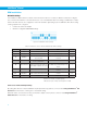
Table 1: Wetted Materials
Component Material
O-ring seals Buna-N
Sensor cap 303 stainless steel
Sensor element isolation barrier Silicone based gel
Port 303 and 304 stainless steel
Sensor Mounting
Mounting Location
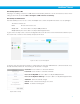
It is recommended that the sensor be placed between 2" (50.8 mm) and 6” (152.4 mm) of the cylinder. To avoid dam-
age to the sensor, do not directly mount the sensor to the cylinder. The maximum distance from the cylinder to the
sensor assembly is 4’ (1219 mm). Responsiveness of the sensor may be reduced due to longer tube lengths.
The sensor should be mounted so that it is part of the cylinder volume. Pneumatic accessories such as ow controls
and quick exhaust valves should not be located between the sensor and the cylinder.
The sensor assembly should be retained to minimize stress on the pneumatic connection and sensor cable.
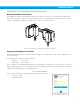
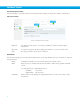
Sensor Orientation
The sensor should be oriented with the port pointed down. This will minimize the chance of debris clogging the port.
The pressure sensor is a dead-end device and cannot be cleaned. If the port becomes clogged, a new sensor should
be installed.
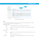
Assembly Torque
The sensors included with an IntelliSense
®
kit come pre-assembled to a pneumatic tting. A situation may arise
where a different tting is required. The port on the sensor is a 10-32 UNF thread. The maximum torque for the sen-
sor is 10 in-lb [1.13 N-m].
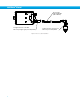
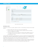
Sensor Cable
The SIM connects to each sensor with a four-wire Female M8 to Female M8 cable (part number CBL-IS-M8-XXX).
The maximum length of this cable is 325 feet (100 Meters). Care should be taken to not over tighten the connection
to the SIM.
The sensor connected to the port labeled Sensor 1 should be installed at the cap or rear of the cylinder. The sensor
connected to the port labeled Sensor 2 should be connected to the head or rod side of the cylinder.