
User Manual

Bimba Manufacturing Company
Monee, IL 60449
TEL 708/534-8544 • FAX: 708/235-2014
Visit our Web Site at: www.bimba.com
Technical Assistance: 1-800-44-BIMBA
Form PFCN-INST-1108
Bimba’s ISO9001 system verifi es that all products produced and delivered meet Bimba’s
rigid quality standards and meet or exceed the expectations of customers. This certifi cate
verifi es that the non-contact Position Feedback Cylinder shipped in this box is free of defects
in workmanship and materials and has been calibrated for 0 to 10 V DC output fully retracted
to fully extended, with 24 V DC applied. If you want to readjust for 0-10 V as fi xtured in your
application, follow the instructions below:
1. Install the PFCN in your application.
Remove the rear end cap exposing the
probe and four adjustment screws.
2. Position the actuator to full retract at 80
psi. Adjust the output as close to zero
as possible using the coarse adjustment
“RET(CS),” and then the fi ne adjustment
“RET(FN).”
3. Position the actuator to full extend at 80 psi. Adjust the output to 10 V DC using the
coarse adjustment “EXT(CS),” and then the fi ne adjustment “EXT(FN).
PFCN Instructions
PCS controller instruction manual – download the most up to date copy at
http://www.bimba.com/Products/PositionControl/.
Wires 6" Leads Plug
Input Red Blue
Ground Black Black
Output White Brown
For optimum performance:
1. Identify your minimum requirements for accuracy and repeatability and make sure they
are achievable before purchasing components.
2. If you are converting the analog feedback voltage into a digital signal, consider A/D
conversion accuracy and time, and use differential A/D conversion (not open ended).
3. Use a single point ground approach with a separate wire from each piece of equipment to
the single point ground location.
4. Physically separate electrically noisy components from sensitive devices and cables.
Noisy components include AC lines and magnetic fi elds.
5. Provide the PFCN and controls with clean, dedicated power supplies (do not share with
electrically noisy valves, relays or solenoids).
6. Order DC powered valves with diode suppression.
7. Order AC powered valves with R-C Snubber suppression.
8. If a valve or relay does not include internal noise suppression add an Okaya model
number XEB0471 RC Snubber across the items power leads (locate it as close as
possible to the noise source). Okaya’s US offi ce is located in Valparaiso, Indiana, and
their phone number is 219-477-4488.
9. Always use the lowest noise (ripple) regulated power supply you can afford for your
sensitive items. If a vendor offers any kind of noise suppression device as an accessory
for their component), order it. Locate it as close to the component as possible.
1 0. Always use twisted, shielded cable (preferably instrumentation grade) for any sensitive
signal path. Use cable with a drain wire (the drain wire is connected to the foil shield); it
is much easier to connect the drain wire to a ground than it is to connect the foil shield to
ground.
11. Always minimize the length of unshielded wire that extends beyond the conductor (try to
expose less than 0.10 inch of unshielded wire).
12. Do not attach both ends of the cable’s shield to ground; attach one end only, preferably at
the data acquisition end. If this is not possible, it is far better to leave both ends “fl oating”
than it is to attach both ends to ground.
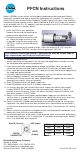
BLACK (Ground)
M8 DIN
WHITE
(Output)
RED (Input)
CONNECTOR