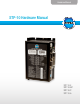
Hardware Manual STP-10 Hardware Manual STP-10-E STP-10-EIP STP-10-2 STP-10-5
Contents Introduction............................................................................................................................................... 3 Features..................................................................................................................................................... 3 Block Diagrams........................................................................................................................................ 4 Getting Started.................
STP-10 Hardware Manual Introduction Thank you for selecting a Bimba DC stepper motor control. We hope our dedication to performance, quality and economy will make your motion control project successful. If there’s anything we can do to improve our products or help you use them better, please call or fax. We’d like to hear from you. Our phone number is (800) 44-BIMBA, or you can reach us by fax at (708) 235-2014. You can also email support@bimba.com.
STP-10 Hardware Manual Block Diagrams 24 - 48 VDC* INPUT X1 INPUT X2 INPUT X3 INPUT X4 INPUT X5 INPUT X6 X7/CWLIM Internal Logic Supply Status MOSFET PWM Power Amplifier Optical Isolation X8/CCWLIM OUTPUT Y1 OUTPUT Y2 OUTPUT Y3 OUTPUT Y4 Option Card DSP Option Card ANALOG IN1 motor encoder RS485 (Optional on STP-10 Drives only) ANALOG IN2 to PC/MMI RS-232 *24 - 80 VDC for STP-10 STP-10-2, STP-10-5 24 - 48 VDC* INPUT X1 INPUT X2 INPUT X3 INPUT X4 INPUT X5 INPUT X6 X7/CWLIM Internal Logic Su
STP-10 Hardware Manual Getting Started This manual describes the use of six different drive models. What you need to know and what you must have depends on the drive model. For all models, you’ll need the following: • A 24-48 volt DC power supply. Please read the section entitled Choosing a Power Supply for help in choosing the right power supply. • A compatible Bimba stepper motor. See section on Recommended Motors. • A small flat blade screwdriver for tightening the connectors (included).
STP-10 Hardware Manual Connecting to the PC using RS-232 • Locate your computer within 8 feet of the drive. • If you have an Ethernet drive, this port is not used. All communcation uses the RJ45 Ethernet connector. • RS-232 drives are shipped with a communication cable. Plug the large end into the serial port of your PC and the small end into the PC/MMI jack on your drive. Secure the cable to the PC with the screws on the sides. Never connect a drive to a telephone circuit.
STP-10 Hardware Manual Connecting the Drive to Your PC using Ethernet This process requires three steps • Physically connect the drive to your network (or directly to the PC) • Set the drive’s IP address • Set the appropriate networking properties on your PC. Addresses, Subnets, and Ports Every device on an Ethernet network must have a unique IP address.
STP-10 Hardware Manual Rotary Switch IP Address 0 10.10.10.10 1 192.168.1.10 2 192.168.1.20 3 192.168.1.30 4 192.168.0.40 5 192.168.0.50 6 192.168.0.60 7 192.168.0.70 8 192.168.0.80 9 192.168.0.90 A 192.168.0.100 B 192.168.0.110 C 192.168.0.120 D 192.168.0.130 E 192.168.0.140 F DHCP Settings 1 through E can be changed using the Bimba IQ® Stepper software (use Bimba IQ® Servo for servo drives). Setting 0 is always “10.10.10.10”, the universal recovery address.
STP-10 Hardware Manual Option 1: Connect a Drive to Your Local Area Network If you have a spare port on a switch or router and if you are able to set your drive to an IP address that is compatible with your network, and not used by anything else, this is a simple way to get connected. This technique also allows you to connect multiple drives to your PC. If you are on a corporate network, please check with your system administrator before connecting anything new to the network.
STP-10 Hardware Manual 3. Scroll down until you see “Internet Properties (TCP/IP)”. Select this item and click the Properties button. On Windows 7 and Vista, look for “(TCP/IPv4)” 4. If the option “Obtain an IP address automatically” is selected, your PC is getting an IP address and a subnet mask from the DHCP server. Please cancel this dialog and proceed to the next section of this manual: “Using DHCP”. 5. If the option “Use the following IP address” is selected, life is good.
STP-10 Hardware Manual Option 2: Connect a Drive Directly to Your PC This is the simplest option: 1. Connect one end of a CAT5 Ethernet cable into the LAN card (NIC) on your PC and the other into the drive. You don’t need a special “crossover cable”; the drive will automatically detect the direct connection and make the necessary physical layer changes. 2. Set the IP address on the drive to “10.10.10.10” by setting the rotary switch at “0”. 3. To set the IP address of your PC: 4. a.
STP-10 Hardware Manual 5. Select the option “Use the following IP address”. Then enter the address “10.10.10.11”. This will give your PC an IP address that is on the same subnet as the drive. Windows will know to direct any traffic intended for the drive’s IP address to this interface card. 6. Next, enter the subnet mask as “255.255.255.0”. 7. Be sure to leave “Default gateway” blank. This will prevent your PC from looking for a router on this subnet. 8.
STP-10 Hardware Manual 4. 5. To set the IP address of the second NIC: a. On Windows XP, right click on “My Network Places” and select properties. b. On Windows 7, click Computer. Scroll down the left pane until you see “Network”. Right click and select properties. Select “Change adapter settings” You should see an icon for your newly instated NIC. Right click again and select properties. a. Scroll down until you see “Internet Properties (TCP/IP)”. Select this item and click the Properties button. b.
STP-10 Hardware Manual Two Wire Systems transmit and receive on the same pair of wires, which can lead to trouble. The host must not only disable its transmitter before it can receive data, it must do so quickly, before a drive begins to answer a query. The STP-10 drives include a “transmit delay” parameter that can be adjusted to compensate for a host that is slow to disable its transmitter. This adjustment can be made over the network using the TD command, or it can be set using the IQ® Stepper software.
STP-10 Hardware Manual Connecting the Power Supply If you need information about choosing a power supply, please read Choosing a Power Supply located on page 27 in this manual. Connect the motor power supply “+” terminal to the driver terminal labeled “V+”. Connect power supply “-” to the drive terminal labeled “V-”. Use 18 or 20 gauge wire. The STP drives contain an internal fuse that connects to the power supply + terminal. This fuse is not user replaceable.
STP-10 Hardware Manual Connecting the Motor Never connect or disconnect the motor while the power is on. Four lead motors can only be connected one way. Please follow the sketch at the right. Six lead motors can be connected in series or center tap. In series mode, motors produce more torque at low speeds, but cannot run as fast as in the center tap configuration. In series operation, the motor should be operated at 30% less than the rated current to prevent overheating.
STP-10 Hardware Manual Connecting an Encoder (Requires the Optional Encoder Feedback Card) The encoder connections use a HD-15 connector, which you must connect to your encoder as shown below. See back page for mating connector information. If your encoder is single ended, connect the encoder outputs to the A+, B+ and Z+ inputs. Leave A-, B- and Z- unconnected. (Z is the encoder index signal and is optional.) 3 4 5 5K 5K Z+ 8.3K Z8 Pin Assignments (facing drive) 12.
STP-10 Hardware Manual Connecting Input Signals The STP drives have three types of inputs: • High speed digital inputs for step & direction commands or encoder following, 5 volt logic • Digital inputs for other signals, 12 - 24 volt logic • Analog inputs for analog speed and positioning modes All drives include eight digital inputs and two analog inputs. • CW & CCW Limit: can be used to inhibit motion in a given direction, forcing the motor and load to travel within mechanical limits.
STP-10 Hardware Manual Connection diagrams follow.
STP-10 Hardware Manual Using High Speed Inputs with 12-24 Volt Signals Most PLCs don’t use 5 volt logic. You can connect signal levels as high as 24 volts to the STEP and DIR inputs if you add external dropping resistors, as shown below. • • For 12 volt logic, add 820 ohm, 1/4 watt resistors For 24 volt logic, use 2200 ohm, 1/4 watt resistors The maximum voltage that can be applied to an input terminal is 24 volts DC. Never apply AC voltage to an input terminal.
STP-10 Hardware Manual Other Digital Inputs 8 XCOM 7 X3/EN Single Ended Inputs The STP drives include four single ended, optically isolated input circuits that can be used with sourcing or sinking signals, 12 to 24 volts. This allows connection to PLCs, sensors, relays and mechanical switches. Because the input circuits are isolated, they require a source of power. If you are connecting to a PLC, you should be able to get power from the PLC power supply.
STP-10 Hardware Manual 12-24 VDC Power Supply + - + output NPN Proximity Sensor – XCOM X3..X6 DRIVE Connecting an NPN Type Proximity Sensor to an input (When prox sensor activates, input goes low). 12-24 VDC Power Supply + - + output PNP Proximity Sensor – X3..X6 DRIVE XCOM Connecting a PNP Type Proximity Sensor to a an input (When prox sensor activates, input goes low).
STP-10 Hardware Manual Connecting Limit Switches The CWLIMIT and CCWLIMIT inputs are used for connecting end of travel sensors. These inputs are differential, which allows you to use signals that are sinking (NPN), sourcing (PNP) or differential (line driver). By connecting switches or sensors that are triggered by the motion of the motor or load, you can force the motor to operate within certain limits. This is useful if a program or operator error could cause damage to your system by traveling too far.
STP-10 Hardware Manual If the sensor output goes low at the limit, select the option “closed” (in the software). If the output is open, or high voltage, choose “open”. Other sensors have sourcing outputs. That means that current can flow out of the sensor output, but not into it. In that case, wire the sensor this way: + DC Power Supply – + Proximity Sensor – output CW LIMIT+ DRIVE CW LIMIT- Analog Inputs A shielded cable is recommended for electrically noisy environments.
STP-10 Hardware Manual Programmable Outputs IN/OUT1 14 Y1 17 YCOM The STP drives feature four digital outputs. These outputs can be set to automically control a motor brake, to signal a fault condition, to indicate when the motor is moving or to provide an output frequency proportional to motor speed (tach signal). Or the outputs can be turned on and off by program instructions like Set Output.
STP-10 Hardware Manual relay 5-24 VDC Power Supply + – Y1/2/3 IN/OUT1 1N4935 suppression diode YCOM Driving a Relay Using Y1, Y2, Y3 relay 5-24 VDC Power Supply + Y4+ IN/OUT1 1N4935 suppression diode Y4- Driving a Relay Using Y4 26 –
STP-10 Hardware Manual Choosing a Power Supply When choosing a power supply, there are many things to consider. If you are manufacturing equipment that will be sold to others, you probably want a supply with all the safety agency approvals. If size and weight are an issue use a switching supply. You must also decide what size of power supply (in terms of voltage and current) is needed for your application.
STP-10 Hardware Manual Recommended Motors Holding Torque Drive Current Setting Resistance Inductance Rotor Inertia Part Number oz-in kg-cm amps ohms mH g-cm2 MTR-DC17T-275-F 62.8 4.52 2.0 1.7 3.0 68 MTR-DC23T-598-F 177 12.7 5.0 0.4 1.2 300 MTR-DC23T-598D-F 177 12.7 5.0 0.4 1.2 300 MTR-DC23T-598-S 177 12.7 5.0 0.4 1.2 300 MTR-DC23T-598D-S 177 12.7 5.0 0.4 1.2 300 MTR-DC23W-598-S 177 12.7 5.0 0.4 1.2 300 MTR-DC23W-598D-S 177 12.7 5.0 0.4 1.
STP-10 Hardware Manual Specifications and Sizing Speed/Thrust Performance, Vertical Orientation, Pounds and Inches/Second Maximum Continuous 29
STP-10 Hardware Manual 30
STP-10 Hardware Manual 31
STP-10 Hardware Manual Motor Heating Step motors convert electrical power from the driver into mechanical power to move a load. Because step motors are not perfectly efficient, some of the electrical power turns into heat on its way through the motor. This heating is not so much dependent on the load being driven but rather the motor speed and power supply voltage. There are certain combinations of speed and voltage at which a motor cannot be continuously operated without damage.
STP-10 Hardware Manual Motor Dimensions OLE-75, -150; No Encoder 120" SHIELDED CABLE A D F N B E L H C Code DC Motor M L H G A B C D E F P6 MTR-DC23T-598-S 0.79 0.25 0.23 0.59 1.498/1.502 0.06 P7 MTR-DC23W-598-S 0.79 0.25 0.23 0.59 1.498/1.502 0.06 P8 MTR-DC23T-601-S 0.79 0.25 0.23 0.59 1.498/1.502 0.06 P9 MTR-DC23W-601-S 0.79 0.25 0.23 0.59 1.498/1.502 0.
STP-10 Hardware Manual OLE-350; No Encoder 120" SHEILDED CABLE A B F N D H E L C G Code DC Motor A M L H B C D E F P10 MTR-DC34T-506-S 1.46 0.50 0.45 1.00 2.873/2.877 0.08 P11 MTR-DC34W-506-S 1.46 0.50 0.45 1.00 2.873/2.877 0.08 OLE-350; Encoder Version 120" ENCODER CABLE 120" SHIELDED CABLE A B F N D E K H L C G M P L H Code 34 DC Motor A B C D E F E10 MTR-DC34T-506-S 1.46 0.50 0.45 1.00 2.873/2.877 0.08 E11 MTR-DC34W-506D-S 1.
STP-10 Hardware Manual Mounting the Drive You can mount your drive on the wide or the narrow side of the chassis using #6 screws. If possible, the drive should be securely fastened to a smooth, flat metal surface that will help conduct heat away from the chassis. If this is not possible, then forced airflow from a fan may be required to prevent the drive from overheating. • Never use your drive in a space where there is no air flow or where other devices cause the surrounding air to be more than 40°C.
STP-10 Hardware Manual Technical Specifications Amplifier Digital MOSFET. 20 kHz PWM. ST5: 24 - 48 VDC, motor current: 0.5 to 5.0 amps/phase peak of sine STP-10: 24 - 48 VDC, motor current: 0.5 to 10 amps/phase peak of sine Digital Inputs Step & Direction: differential, optically isolated, 5V logic. 330 ohms internal resistance. 0.5 µsec minimum pulse width. 2 µsec minimum set up time for direction signal. All other digital inputs: optically isolated, 12 - 24V logic. 2200 ohms. Maximum current: 10 mA.
STP-10 Hardware Manual Mating Connectors and Accessories Mating Connectors Motor/power supply: PCD P/N ELV06100, included with drive. IN/OUT1: DB-25 male. Bimba P/N 5-747912-2. Shell Kit Bimba P/N 5-748678-3. Included. Optional encoder feedback: HD-15 male. Norcomp P/N 180-015-102-001. Shell Kit Bimba P/N 5-748678-1. Not included.
STP-10 Hardware Manual Alarm Codes In the event of an error, the red and green LEDs on the main board will flash in alternating red-green patterns as shown below. The pattern repeats until the alarm is cleared.
STP-10 Hardware Manual Bimba Manufacturing Company P.O. Box 68 Monee, Illinois 60449-0068 Phone: 708-534-8544 Toll Free: 800-44-BIMBA Fax: 708-235-2014 Email: cs@bimba.com www.bimba.