INSTALLATION MANUAL UL2 Front Mount MODELS 4400 FM 6600 FM HydroHoist Boat Lifts ® R HydroHoist Marine Group P.O. Box 1286 Claremore, OK USA 74018 1-800-825-3379 www.boatlift.com Pub.
HydroHoist Marine Group HydroHoist Marine Group Product Installation and Use Warning Disclaimer ASSEMBLY, INSTALLATION OR REPAIRS OF A HYDROHOIST BOAT LIFT SHOULD ONLY BE PERFORMED BY AN AUTHORIZED HYDROHOIST TECHNICIAN. IF ASSEMBLY, INSTALLATION AND/OR REPAIR IS PERFORMED BY UNAUTHORIZED PERSONS, SERIOUS PERSONAL INJURY AND/OR PROPERTY DAMAGE COULD OCCUR.
HydroHoist Marine Group Model: 4400/6600/ UL2FM Publication: 10/14/08 CONTENTS Getting Started - Section 1 Site Preparation - Section 2 Assembly - Section 3 Installation - Section 4 Final Adjustments - Section 5 Trouble Shooting - Section 6 Parts List - Section 7
Getting Started Sec. 1 Pg. 1 HydroHoist Marine Group Model: 4400/6600/ UL2FM Publication: 10/14/08 Getting Started Assembly Platform Assembly should be done on a flat, level surface. A flat-bed trailer is preferred, but a boat trailer with planks across the frame will work, provided that the assembly surface is flat and level Tools A list of tools needed for hoist assembly is given below. In addition to these, tools for boat dock preparation, dock bumper removal, etc. may also be required.
Site Preparation Sec. 2 Pg. 1 HydroHoist Marine Group Model: 4400/6600/ UL2FM Publication: 10/14/08 Site Preparation Verify The Boat Stall or Mooring Location. ♦ If the hoist is being installed in a commercial marina or multi-slip boat dock, confirm the correct mooring location for hoist and boat. The boat specifications. ♦ ♦ ♦ ♦ ♦ ♦ ♦ ♦ ♦ ♦ Inspect Make ____________________________ Model ___________________________ Length _____________ Beam ______________ Dry Weight of boat ________ lbs.
Assembly Sec. 3 Pg. 1 HydroHoist Marine Group Model: 4400/6600/ UL2FM Publication: 10/14/08 Assembly Instructions Description The assembly instructions presented within this section represent the steps for assembling the Model 4400FM & 6600FM HydroHoist Boat Lift. It is recommended that before assembling the components, you read and understand each procedural step to become familiar with how all parts are assembled.
HydroHoist Marine Group Model: 4400/6600/ UL2FM Publication: 10/14/08 Assembly Sec. 3 Pg.
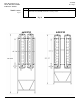
Assembly Sec. 3 Pg. 3 HydroHoist Marine Group Model: 4400/6600/ UL2FM Publication: 10/14/08 Tank Location Fig. B Step 1.1 Procedure Align the Tanks [1] parallel with each other and with the Air Injection Nipple to the front of the hoist assembly and in the 6 o'clock position. Fig.
Assembly Sec. 3 Pg. 4 HydroHoist Marine Group Model: 4400/6600/ UL2FM Publication: 10/14/08 Tank Bracket Assembly Step Procedure Fig. B 1.1 Fig B Place the tube brackets [9] in the longitudinal channels which span the top of the tanks. Step Procedure 1.2 Fig C Snap the UL2 side brackets [14] into place, followed by placing the Single Piece Tank Bracket [10] on top of the side bracket and attaching with fasteners. Fasteners per single piece/plastic bracket: (2ea.
Assembly Sec. 3 Pg. 6 HydroHoist Marine Group Model: 4400/6600/ UL2FM Publication: 10/14/08 Channel Assembly Step 3.1 Fig. E 3.2 3.3 Procedure Attach front and rear Cross Channel [11] to Single Piece Tank Brackets[10]. Note: Position Cross Channel [11] with flanges of Channel to rear of hoist. Fasteners per Upper Tank Band: (4 ea.) 1/2” x 1-1/2” bolt, nut & lockwasher.
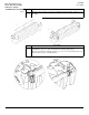
Assembly Sec. 3 Pg. 7 HydroHoist Marine Group Model: 4400/6600/ UL2FM Publication: 10/14/08 Note... Positioning... Fig. F Hull Support Assembly The parts installed in the next steps may have to be moved to better fit the bottom of the boat after it has been lifted. Accurate measurements of the boat’s hull before assembly and careful attention to these steps may prevent repositioning the parts over the water.
Assembly Sec. 3 Pg. 8 HydroHoist Marine Group Model: 4400/6600/ UL2FM Publication: 10/14/08 Frame Weldment Assembly Step 5.1 Procedure Under the Frame Sections [13 & 14] suspend by rope or chain, a 2x4 x 8 foot board as shown in Fig. G 5.2 With the “Square Tube Section” of the Frame Weldment Assembly [12] still on the ground, lift the “Drop V” Section of the Weldment Assembly [12] and place on top of the 2x4 board and in position to (later) be bolted to the frame.
HydroHoist Marine Group Model: 4400/6600/ UL2FM Publication: 10/14/08 Mooring Tube Assembly Sec. 3 Pg. 9 Step 7.1 Fig. H 7.2 7.3 7.4 Procedure Determine the location of the Mooring Tube Assembly: FM 4400 - the rear Cross Channel [11] is preferred, the center Cross Channel is optional. FM 6600 - the center Cross Channel [11] is mandatory. Attach Mooring Pipe Clamp [18] to Cross Channel [11]. Fasteners: (4 ea.) 1/2” x 11/2” bolt, nut & lockwasher. Tighten these bolts at this time.
HydroHoist Marine Group Model: 4400/6600/ UL2FM Publication: 10/14/08 Assembly Sec. 3 Pg. 10 Hose Assembly Step 9.1 Procedure Cut Hose [16] in half and secure one end of each hose to the nipple of the tank and one end to the valve in the control. Secure with Hose Clamps. Launching the Hoist Step 10.1 Procedure Secure the Control Unit [15] to a Hull Support Column [4] in the front of the Hoist. Make sure that all valves are closed in the “Dry-Dock” position. 10.2 Insert Tank Plugs (Pt. No.
Installation HydroHoist Marine Group Model: 4400/6600/ UL2FM Publication: 10/14/08 Installation Sec.4 Pg. 1 Step Procedure Selecting Position for Hoist 1.1 Move the hoist fully into the boat stall and position the Mooring Tube [19] 2 inches from the side of the dock. Fig. I 1.2 With the hoist held in the proper position, place a mark on the dock at TWO points: 1-The location of the Pivot Bushing of the left/port Side Channel [14].
Installation Sec.4 Pg. 2 HydroHoist Marine Group Model: 4400/6600/ UL2FM Publication: 10/14/08 Front Mooring Attachment Step Procedure 3.1 Attach Pivot Connecting Bracket [7], with the pivot hole 10 inches above the water line, to Vertical Angle [32] . Fasteners per Bracket: (2 ea.) 1/2" x 1-1/2" bolt, nut & lockwasher. Tighten these fasteners at this time to 40 ft-lbs. 3.
Installation Sec.4 Pg. 3 HydroHoist Marine Group Model: 4400/6600/ UL2FM Publication: 10/14/08 Side Mooring Attachment Step 4.1 Fig. L&M 4.2 4.3 Fig. L Procedure Assemble Mooring Collar Assembly [20] to Side Dock Bracket [8]. Fasteners: (2 ea.) 3/8" x 4-1/2" Bolt, Nut and Lockwasher. Note: The Collar Assembly may be positioned high or low, by attaching to the Dock Bracket with either the Center and Top holes, or Center and Bottom holes.
Installation Sec.4 Pg. 4 HydroHoist Marine Group Model: 4400/6600/ UL2FM Publication: 10/14/08 Lowering the Hoist Step Procedure 6.1 Rotate the Control Unit Handle to the Lift/Launch position. Note: It may be necessary to turn blower on for three or four seconds to purge any water trapped in the air hoses; additionally, without the weight of the boat, air will exhaust slowly from the tanks.
Installation Sec.4 Pg. 5 HydroHoist Marine Group Model: 4400/6600/ UL2FM Publication: 10/14/08 Lifting the Boat Balance and Load Step Procedure 7.3 Hold the front of the boat centered over the hoist, pushing the boat to stern gently until the Guide Ropes are taut. The Guide Ropes center the boat's stern over the hoist, and keep the transom aligned over the Hull Support Pads. 7.
HydroHoist Marine Group Model: 4400/6600/ UL2FM Publication: 10/14/08 Final Adjustments Sec. 5 Pg. 1 Final Adjustments Final Inspection Wrapping Up CAUTION: DESTRUCTIVE WIND OR WATER CONDITIONS Step 1.1 Procedure Operate the hoist again - launch then lift - checking for proper positioning of the boat and Pads, and for proper operation of the lift, and Moorings. ♦ ♦ ♦ ♦ Loosely, secure a bow line to the boat and to the boat dock. Confirm that the operating Instructions are in the Control Unit.
HydroHoist Marine Group Model: 4400/6600/ UL2FM Publication: 10/14/08 Trouble Shooting Sec. 6 Pg. 1 Trouble Shooting CONDITION: Hoist will not completely lift boat from water or stern remains low. CAUSE: A B C Boat loaded too far to rear. Water or equipment in boat creating additional weight. Boat weight exceeds lifting capacity of hoist. CORRECTION: A Reposition boat forward to balance weight over hoist and adjust the Guide Ropes to maintain proper positioning. Remove water or equipment.
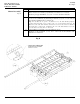
Parts List Sec. 7 Pg. 1 1 2 3 4 5 6 7 8 9 10 11 12 13 14 15 16 18 19 20 21 22 5015500 5015510 4442000 5025600 3031700 4031150 4210001 5049000 4440040 4440050 4220501 4210070 4440012 4440000 4441200 4441000 4441300 4441100 5822005 3072512 4440020 4440034 4440054 2914702 2908400 6966400 TANK ASSEMBLY - UL2 4400 TANK ASSEMBLY - UL2 6600 PAD ASSY.-12' HULL SUPT. PAD - HULL SUPPORT-14' BRACE-HULL PAD-25 3/4 IN ANGLE HULL SUPT COL UNIV UL2 SIDE BRACKET - PLASTIC DK BRKT- HVY DUTY PIVOT - CONNECTING BRKT.
UL2 Front Mount R