Operating Manual APT.line™ C 150 (E2) CO2 Incubators with FPI-sensor system and display controller RP1 Model C150 C150 C150-UL C150-UL C150 C150 Art. No. 9040-0078, 9140-0078 9040-0081, 9140-0081 9040-0079, 9140-0079 9040-0082, 9140-0082 9040-0080, 9140-0080 9040-0083, 9140-0083 Door hinges right left right left right left Voltage 230 V 230 V 115 V 115 V 100 V 100 V BINDER GmbH Address Post office box 102 D-78502 Tuttlingen Tel. +49 7462 2005 0 Fax +49 7462 2005 100 Internet http://www.binder-world.
EC – declaration of conformity EG – KONFORMITÄTSERKLÄRUNG EC - DECLARATION OF CONFORMITY CE - DECLARATION DE CONFORMITE Anbieter / Supplier / Fournisseur: BINDER GmbH Anschrift / Address / Adresse: Im Mittleren Ösch 5, D-78532 Tuttlingen Produkt / Product / Produit: CO2 -Inkubator CO2 Incubator Incubateur à CO2 Typenbezeichnung / Type / Type: C 150 Die oben beschriebenen Produkte sind konform mit folgenden EG-Richtlinien: The products described above are in conformity with the following EC guidelin
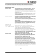
Die oben beschriebenen Produkte sind konform mit folgenden harmonisierten Normen: The products described above are in conformity with the following harmonized standards: Les produits décrits ci-dessus sont conformes aux normes harmonisées suivantes: Sicherheit / safety / sécurité: EN 61010-1:2010 Sicherheitsbestimmungen für elektrische Mess-, Steuer-, Regel- und Laborgeräte – Teil 1: Allgemeine Anforderungen (DIN EN 610101:2011, VDE 411-1:2011) Safety requirements for electrical equipment for measurement,
D-78532 Tuttlingen, 21.08.2012 BINDER GmbH P. M. Binder B.
Product registration C 150 (E2) 12/2012 page 5/90
Contents EC – declaration of conformity ...................................................................................................................... 2 Product registration ....................................................................................................................................... 5 1. SAFETY .................................................................................................................. 9 1.1 1.2 Legal considerations ................................
8. CONTROLLER RP1 SETTINGS .......................................................................... 41 8.1 8.2 Altitude of the installation site above sea level ................................................................................. 41 Entering the set points of temperature and CO2 ............................................................................... 43 9. TEMPERATURE SAFETY DEVICES ................................................................... 44 9.1 9.
16. MAINTENANCE, AND SERVICE ......................................................................... 71 16.1 16.2 16.3 16.4 Maintenance intervals, service .......................................................................................................... 71 Checking the air jacket heating fan ................................................................................................... 71 Gas inlet fine filter ...................................................................................
Dear Customer, For the correct operation of the CO2 incubator C 150, it is important that you read this operating manual completely and carefully and observe all instructions as indicated. Failure to read, understand and follow the instructions may result in personal injury. It can also lead to damage to the unit and/or poor equipment performance. 1. Safety This operating manual is part of the components of delivery. Always keep it handy for reference.
WARNING Indicates a potentially hazardous situation which, if not avoided, could result in death or serious (irreversible) injury CAUTION Indicates a potentially hazardous situation which, if not avoided, may result in moderate or minor (reversible) injury CAUTION Indicates a potentially hazardous situation, which, if not avoided, may result in damage to the product and/or its functions or to property in its proximity. 1.2.2 Safety alert symbol Use of the safety alert symbol indicates a risk of injury.
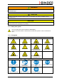
Prohibition signs Do NOT touch Do NOT spray with water Do NOT climb Information to be observed in order to ensure optimum function of the product. 1.2.4 Word message panel structure Type / cause of hazard. Possible consequences.
Figure 3: Position of labels on the CO2 incubator C 150-UL (door hinged right) Figure 4: Position of labels on the CO2 incubator C 150-UL (door hinged left) Keep safety labels complete and legible. Replace safety labels that are no longer legible. Contact BINDER Service for these replacements. 1.
Nominal temperature 190 °C 374°F Enclosure protection IP 20 Temp. safety device DIN 12880 Class 3.1 Art. No. 9040-0078 Project No. 1,40 kW 230 V 1 N ~ 6,1 A 50/60 Hz US PATS 4585923 / 5222612 / 5309981 5405194 / 5601143 / 5773287 / 6079403 D 78532 Tuttlingen / Germany Tel. + 49 (0) 7462/ 2005-0 Internet: www.binder-world.com C 150 Serial No. 00-00000 Made in Germany Figure 6: Type plate C 150 (standard unit) Indications of the type plate BINDER C 150 Serial No.
1.5 General safety instructions on installing and operating the CO2 incubator With regard to operating the CO2 incubator C 150 and to the installation location, please observe the guideline BGI/GUV-I 850-0 on safe working in laboratories (formerly BGR/GUV-R 120 or ZH 1/119 laboratory guidelines issued by the employers’ liability insurance association) (for Germany).
The CO2 incubators were produced in accordance with VDE regulations and were routinely tested in accordance to VDE 0411-1 (IEC 61010-1). CAUTION The glass door and the inner chamber will become hot during operation. Danger of burning. ∅ Do NOT touch the glass door, the inner surfaces or the charging material during operation. WARNING Stability hazard. Danger of injury. Damage to the unit and the charging material. Housing cover breakaway. ∅ Do NOT climb on the lower housing cover.
1.7 Precautions when handling gas cylinders General information for safe handling of gas cylinders: • Store and use gas cylinders only in well-ventilated locations. • Open the gas cylinder valve slowly to avoid pressure surges • Secure gas cylinders during storage and use against falling (chaining). • Transport gas cylinders with a cylinder cart, do not carry, roll, or throw them. • Always close the valve even with apparently empty cylinders; screw on the cap when not in use.
Always use proper protective equipment (clothing, gloves, safety glasses, etc.). Always follow good hygienic practices according to GLP/SOP protocols. Each individual operating the C 150 incubator is responsible for his or her own safety 2. Unit description The CO2 incubators C 150 are equipped with a microprocessor controller for temperature and CO2 levels and a digital display accurate to one-tenth of a degree resp. 0.1 vol.
2.
2.3 Connection panel at the rear of the unit (11) (12) (13) (14) (15) Figure 8: Rear connection panel C 150 (11) Power cable (12) Miniature fuse (13) Connection socket for zero-voltage relay alarm contact (14) Quick acting closure socket for CO2 gas cylinder (15) Ethernet interface for computer communication (option) 2.
2.5 Unit doors The outer door of the C 150 is equipped with a heater on its inner side. The door must be closed while the unit is operating normally in order to ensure stable climatic conditions in the inner chamber. An additional glass door enables viewing of the samples without disturbing the temperature in the interior and contaminating the samples sealing the interior of the C 150. When the outer door is open, the CO2 intake valve automatically closes.
3.2 Guidelines for safe lifting and transportation After operation, please observe the guidelines for temporarily decommissioning the unit (chap. 17.2). Empty the water pan before moving the incubator. In case of any spilling of the contents, shut down the incubator and dry it out carefully and completely CAUTION Sliding or tilting the unit. Damage to the unit. Risk of injury by lifting heavy loads. Transport the unit in its original packaging only.
3.3 Storage Intermediate storage of the unit is possible in a closed and dry room. Observe the guidelines for temporary decommissioning (chap. 17.2). • Permissible ambient temperature range for storage: -10 °C / 14°F to +60 °C / 140°F. • Permissible ambient humidity: max. 70% r.H., non-condensing When after storage in a cold location you transfer the unit to its warmer installation site, condensation may form in the inner chamber, on the housing or in the sensor compartment of the CO2 measurement.
Avoid direct solar radiation on the unit. • Permissible ambient humidity: 70% r.H. max., non-condensing. • Installation height: max. 2000 m / 6561.7 ft above sea level. After the incubator has been turned on for the first time, enter the altitude of the site above sea level into the RP1 controller (chap. 8.1). • Wall distances: rear 100 mm / 3.94 in, sides 50 mm / 1.97 in. Notes on handling carbon dioxide (CO2) Carbon dioxide (CO2) in high concentrations is hazardous to health.
4.2 CO2 sensor 4.2.1 General notes Connect or remove the CO2 sensor without rotating and only when the incubator is turned off. Remove the CO2 sensor before removing or replacing its filter cap. The PTFE filter of the CO2 sensor prevents dirt and humidity from intruding into the measuring cell. It is available as a spare part. Replace it whenever it is damaged or soiled. The accuracy of the indicated values of CO2 depends on the ambient air pressure (approx. 0.08 vol.-% per 10 mbar / 0.15 psi).
4.3 Water pan The water pan permits high humidity without condensation on the inner walls of the incubator. Place the positioning frame on the two marks at the bottom of the inner chamber. Then put the water pan in the positioning frame. Make sure that the water pan has firm contact with the inner chamber bottom and rests tightly on it. Figure 13: Placed positioning frame Figure 14: Placed water pan Fill the water pan with 300 ml of distilled, sterilized water. We recommend cleaning (chap. 15.
The valve of the gas cylinder always must be closed before screwing on or unscrewing the gas hose. WARNING Opening the cylinder valve when the cylinder is not connected. Sudden release of the stored pressure energy. Risk of injury. Close the gas cylinder valve before connecting or removing the gas hose. After connecting the gas cylinder, check all gas connections for leaks (e.g. with leak spray or diluted soap solution). 4.4.
The following steps are required: Ensuring the correct CO2 output pressure A gas supply pressure above 2.5 bar / 36 psi will result in unit damage. Use a pressure reducer and make sure to avoid any excessive outlet pressure when connecting the gas hose to the incubator. The real outlet pressure of gas cylinders, sets of gas cylinders or central gas supplies am on the second manometer must not exceed 2.5 bar / 36 psi. CAUTION Excessive outlet pressure > 2.5 bar / 36 psi. Damage to the unit.
4.4.2 Connecting the gas hose to the unit rear The gas hose, which will be used to establish the connection to a gas cylinder, is already attached to the hose nozzle and secured by a hose clamp. Plug the hose nozzle into the corresponding quick acting closure socket (a) located at the rear of the unit. This quick acting closure socket is closed by a rubber cover (b). Only use the supplied hose nozzle to connect to the quick acting closure socket.
4.4.3 Gas cylinder connection kit (option) The gas cylinder connection kit for CO2 (Art. no.
4.5 Electrical connection • The CO2 incubator C 150 has a fixed power supply connection cable 1800 mm / 70.87 inches in length and a shock-proof plug. Voltage 230 V (1N~) +/- 10%, 50/60 Hz • Prior to connection and start-up, check the power supply voltage. Compare the values to the specified data located on the unit’s type plate (centrally located at the bottom of the left-hand side of the unit, see chap. 1.
5. Start up After connecting the supply lines, turn on the unit by the main power switch (2). After turning on the incubator for the first time, enter the altitude of the site above sea level into the controller RP1 (chap. 8.1). Warming chambers may release odors in the first few days after commissioning. This is not a quality defect. To reduce odors quickly we recommend heating up the chamber to its nominal temperature for one day and in a well-ventilated location. 6.
Figure 18: Normal Display of controller Upper display: current inner chamber temperature LED “ °C” lit: inner chamber temperature displayed in °C Lower display: current CO2 concentration LED “%CO2” lit: CO2 concentration displayed in vol.-% CO2 6.1 Preset factory parameters The unit is supplied with the following basic preset parameters: Temperature set point CO2 set point Safety controller class 3.
Open the CO2 supply's pressure reducer valve and set a CO2 primary pressure of 2.0 bar / 29 psi. Set the main power switch (2) to position I. The pilot lamp shows the unit is ready for operation. There is a subsequent brief startup phase in which the display items at the edges of the upper controller display light up successively. After a few seconds, the upper display shows the current interior temperature of the C 150 and the lower display shows the current CO2 interior concentration.
7.1 Selecting and setting the operating functions The controller's lower display always shows the operating function (e.g. “SP” = temperature set point) and the upper display shows the associated value (e.g. 37.0). When the value in the upper display shows the temperature in °C or a CO2 concentration in % CO2, the corresponding yellow LED to the right of the display will light up.
Operating functions that can be set in operating mode HAND Display Setting range Operating function 0.0 °C to 50.0 °C Temperature set point Must be at least 7 °C / 12.6°F above the ambient temperature in order to ensure a stable temperature inside the C 150. 0.0 vol.-% to 20.0 vol.-% CO2 set point Common value: 5.0 vol.-% (factory setting), or depending on the NaHCO3 concentration of the culture medium (Figure 27 page 55). 0.0 °C to 60.
7.3 Operating mode USER: Advanced settings • In Normal display, press “MODE” and “EXIT” simultaneously for 3 seconds to access the options for selecting the C 150's operating modes. Figure 21: Selecting the operating mode • Press “▲”until the value “OP.U” (operating mode USER) appears in the upper display. • Press “MODE”. The display to enter the password appears. The operating mode USER is password-protected by a number. The password is preset to "1" in factory.
Operating functions in operating mode USER Display Setting range Operating function 0.0 °C to 50.0 °C Temperature set point Must be at least 7 °C / 12.6 °F above the ambient temperature in order to ensure a stable temperature inside the C 150. 0.0 vol.-% to 20.0 vol.-% CO2 set point Common value: 5.0 vol.-% (factory setting), or depending on the NaHCO3 concentration of the culture medium (Figure 27 page 55). 0.0 km to 2.
Display Setting range Operating function 0.0 °C to 60.0 °C Safety controller set point when set point type is “Limit” (Lit) Limit value, i.e., maximum permitted absolute temperature value. When exceeded, the safety controller triggers an alarm. For technical reasons, the limit value should exceed the temperature set point by at least 2 °C. Typical value: 39.0 °C / 102.2°F. 0.1 K to 10 K Safety controller set point when set point type is “Offset” (OFS) Offset value, i.e.
Display Setting range Operating function Firmware revision of safety controller for service / maintenance purposes. Data record (year) for service / maintenance purposes. Data record (month) for service / maintenance purposes. Data record (day) for service / maintenance purposes. Data set version for service / maintenance purposes. OFF, or -199,9 °C to +300 °C Temperature adjustment serves to adjust the temperature sensor. OFF, or -10.0 vol.-% to 110.0 vol.
7.4 Operating mode LOCK: Locking/unlocking of the operating functions’ settings by operating mode HAND To avoid operating functions being changed by unauthorized persons, you can lock the operating functions’ settings. • In operating mode HAND, define a 3-digit numeric password in operating function “PA.H”. Locking the operating functions of operating mode HAND: • In Normal display, press “EXIT” and “MODE” simultaneously for 3 seconds to access operating mode selection. In the upper display, “OP.
• Enter the password using the “▲” and “▼”buttons. • Confirm the entry with “MODE”. The controller returns to Normal display. If you have selected any password other than zero, operating mode HAND is temporarily unlocked. Changing the operating functions in operating mode HAND is now possible until a period of 30 sec. has passed with no activity. 30 seconds after the last keypad entry, the operating functions are relocked (display “OP.L”). To permanently unlock the settings, set operating function “PA.
Toggle to operating mode USER Operating mode HAND Operating mode USER If operating mode HAND appears, toggle to operating mode USER with the arrow keys. Password request Password entry (factory setting: “1”). 4x Entry of altitude Entry of the current altitude [km] above sea level with arrow keys. After 30 seconds the controller reverts to Normal Display automatically. Unit of altitude above sea level for entry and displayed value: kilometer [km] Correlation feet [ft] to kilometer [km]: see chap. 19.
8.2 Entering the set points of temperature and CO2 Normal Display Entry of temperature set point Entry of temperature set point with arrow keys. Entry of CO2 set point Entry of CO2 set point with arrow keys. After 30 seconds the controller reverts to Normal Display automatically. When setting a lower temperature set point, in order to save time, we recommend cooling down the unit by turning it off and opening both doors of the unit.
Note when setting high gas concentrations Carbon dioxide (CO2) in high concentrations is hazardous to health. It is colorless and almost odorless and therefore practically imperceptible. Any CO2 gas that may escape must be safely led out via good room ventilation or a suitable connection to an exhaust system. We recommend installing a CO2 warning system. WARNING High concentration of CO2 (> 4 Vol.-%). Danger of death by suffocation. Danger of poisoning. ∅ Do NOT set up units in non-ventilated recesses.
The settings of the safety controller are inactive during sterilization (chap. 15.4). They become functional again following abortion of the sterilization and/or the restart of the unit at the main power switch. 9.2.1 Setting the safety controller set point type Select the safety controller set point type in operating mode USER (chap. 7.3). The operating function “At.S” specifies the safety controller set point type “Limit” (Lit) or “Offset” (OFS).
12 x Selecting the set point type Selecting set point type “Limit” Selecting set point type “Offset” Change using the arrow keys Select the desired set point type. After 30 seconds the controller reverts to Normal Display automatically. 9.2.2 Setting the safety controller set point You can check and set the safety controller set point in operating modes HAND (chap. 7.2) or USER (chap. 7.3). • With set point type “Limit” (Lit), operating function “AL.
Toggle to operating mode USER Operating mode HAND Operating mode USER If operating mode HAND appears, toggle to operating mode USER with the arrow keys. Password request Password entry (factory setting: “1”). 10 x Depending on the selected set point type (chap. 9.2.1) a different display appears: Entry of limit value or offset value With set point type Limit: Enter a limit value With set point type Offset: Enter an offset value or Entry of limit value using the arrow keys.
10. Alarm functions 10.1 Alarm functions overview When operational faults occur, the controller triggers visual and audible alarm signals. The LED “ALARM” always flashes when an alarm signal is emitted. A zero-voltage relay alarm output (13) (chap. 10.3) permits transmission of the alarm e.g., to a central monitoring system.
10.3 Zero-voltage relay alarm output Collective alarm output via the zero-voltage relay alarm contact The CO2 incubator is equipped at the rear with a zero-voltage relay output (13) for the temperature and CO2, which permits the transmission of alarms to an external monitoring system in order to monitor and record the alarm signals. The zero-voltage relay alarm output switches immediately, as soon as the red LED “ALARM” lights up on the controller display.
10.4 Safety controller temperature alarm The set temperature value (set point type “Limit” or “Offset”) was exceeded. • Immediate alarm • Visual display LED Upper display, alternating Temperature Alarm code Flashes continually lit • Audible alarm: buzzer (ongoing sound) • Switching the zero-voltage relay alarm output. Actions: • Check the setting of the operating function “Al.S” (limit temperature) or “Ot.S” (offset temperature) in operating modes HAND (chap. 7.2) or USER (chap. 7.3).
Temperature too low (under temperature alarm): • Check that the outer door is closed properly. • Check the door's seals for any damage. Replace any damaged seals. Temperature too high (over temperature alarm): • Check whether samples were inserted into the C 150 that produce heat under the climate conditions in the unit. • Check the ambient conditions. The ambient temperature must be at least by 7 °C / 12.6 °F below the temperature set point of the C 150. Protect the C 150 from direct sunlight.
10.7 CO2 tolerance range alarm (CO2 over/under concentration) The main controller CO2 alarm. The CO2 concentration has risen above or fallen below the CO2 alarm threshold. • The alarm signal is usually emitted immediately upon the fault occurring, but no alarm signal is emitted during the CO2 alarm delay time after the outer door is closed.
Actions: • Check that you have set the pressure on the pressure reducer at 2.0 bar / 29 psi above the ambient air pressure, and that all the valves are open for the gas supply. • Where the CO2 supply is a pressurized gas cylinder, check that the cylinder still contains sufficient CO2. If necessary, replace the gas cylinder. Observe the precautions when handling gases and the correct outlet pressure (chap. 4.4). • Check whether the primary pressure is high enough at the central CO2 supply.
10.10 Failure of CO2 sensor A sensor fault alarm display takes priority over all other operational displays and alarm signals on the controller. • Immediate alarm • Visual display: Lower Display, flashing Alarm code LED Meaning Failure of CO2 sensor: CO2 intake valve closed Flashes • Audible alarm: buzzer (intermittent sound) • Switching the zero-voltage relay alarm output Actions: • Turn off the C 150. • If necessary, clean, disinfect and sterilize the C 150. • Please contact BINDER Service. 11.
12. Reference measurements You can take reference measurements of the temperature and CO2 via the silicone measuring port (8) located the inner glass door. Reference temperature measurements always take place under equilibrated conditions with both doors closed. 12.1 CO2 reference measuring There are three possibilities to perform CO2 test measurements between the recommended annual maintenance procedures. To test the CO2 concentration inside an incubator, see chapters 12.1.1 to 12.1.3. 12.1.
Example: If a pH of 7.2 is measured in a medium buffered with 2.20 g NaHC03 per liter, there must be 8 vol.-% CO2 surrounding this medium. 12.1.2 Measuring CO2 directly via chemical indicator tubes This is a common do-it-yourself test for many users. A chemical color reaction in a glass tube shows the CO2 concentration. A standardized volume of air from inside the incubator has to be suctioned through this glass tube to get a quantitative test result.
12.1.3 Measuring CO2 directly with an electronic infrared measuring device The easiest way of measuring the CO2 concentration is by electronic sensor systems. BINDER offers the portable measuring device model CTM 01 that was specifically designed to measure temperature and CO2 concentration inside CO2 incubators. The CTM 01 is suitable both for reference measurements in certified laboratories, and for service purposes. Please contact the BINDER INDIVIDUAL team. 12.
WARNING High concentration of CO2 (> 4 Vol.-%). Risk of death by suffocation. Danger of poisoning. Tightly close each access port with two plugs during operation. 13.2 Base on castors (option) In order to obtain easy access to the incubator and to avoid contamination of the incubator caused by soil pollution, BINDER recommends using the base on castors. The mounting instructions 7001-0147 delivered with the base on castors describe its installation (Art. No. 9051-0024). 13.
14. Avoiding microbial contamination The main types of microbial contaminants in cell and tissue culture are bacteria, fungi, yeast, mycoplasma, and viruses. This chapter gives an overview of potential sources of contamination and precautions and measures to eliminate them. 14.1 Cells and media • Primary cultures from the original tissue • Cells/cell lines from unknown sources or from cell banks: Use only cells of known and tested origin. Monitoring and routine screening of new cultures.
Examples of general rules to reduce the contamination risks • Reduce hand germ count (wash hands with antimicrobial soap, dry with paper tissues, and rub dry hands with alcoholic solution). • Wear appropriate clothing (work coat, shoes, face mask) • Keep as few personnel as possible in the cell culture lab. Examples of sterile working method • Work "clean-to-dirty", i.e.
14.5 Handling the CO2 incubator C 150 Any manipulation of the CO2 incubator involves some contamination risks, from installation to opening of the doors and regular cleaning. Installation away from sources of contamination • Do not place the CO2 incubator on the floor or close to windows and doors. Use the optional stand, if appropriate. Reduce the periods in which the door is open. • Do not open the door too frequently. • Placing items in order inside the incubator results in shorter door opening times.
15. Cleaning, decontamination / disinfection, and sterilization DANGER Electrical hazard. Danger of death. ∅ Do NOT spill water or cleaning agents over the inner and outer surfaces. Before cleaning, turn off the unit at the main power switch (2) and disconnect the power plug. Completely dry the appliance before turning it on again. 15.1 Cleaning Disconnect the CO2 incubator from the power supply before cleaning. Disconnect the power plug. Wipe the surfaces with a moistened towel.
With every cleaning method, always use adequate personal safety controls. Following cleaning, leave the unit door open or remove the access port plugs. The neutral cleaning agent may cause health problems in contact with skin and if ingested. Follow the operating instructions and safety hints labeled on the bottle of the neutral cleaning agent. Recommended precautions: To protect the eyes use sealed protective goggles.
In case of eye contact, the disinfectant spray may cause eye damage due to chemical burns. Follow the operating instructions and safety hints labeled on the bottle of the disinfectant spray. Recommended precautions: To protect the eyes use sealed protective goggles. VORSICHT Eye contact. Eye damage due to chemical burns. ∅ Do NOT empty into drains. Wear protective goggles.
Recommended procedure: • Turn off the unit • Pull out the sensor • Spray the sensor head with alcohol or wipe it clean with a soaked cloth. Observe the reaction time of the disinfectant used. • Before reinserting the CO2 sensor, it must be completely dry. • The filter in the front of the sensor only needs replacing when damaged or dirty. The CO2 sensor head was especially adjusted for the specific chamber. To avoid confusion, an adhesive label with a serial number is adhered to the sensor head.
The precise duration of the entire sterilization cycle depends on the ambient temperature at the installation site and can thus vary. At an ambient temperature of 25 °C / 77 °F, the total duration is approx. 12 hours. You can shorten the cooling-down time by aborting the sterilization cycle (chap. 15.5) during the cooling-down phase, i.e. no sooner than after 6 hours. During sterilization, the CO2 valve is closed and the CO2 controller turns off entirely. 15.4.
Figure 33: Initial sterilization display No sterilization can be started if the CO2 sensor is still plugged-in. You cannot start the sterilization if the operating mode HAND is locked. This is displayed by an error message. If this happens, unlock the operating mode HAND (chap. 7.4). Figure 34: Error message if operating mode HAND is locked or if the CO2 sensor is still plugged-in. • Press “▲”. The upper display toggles from “OFF” to “ON”. • Press “MODE” to start the sterilization cycle.
CAUTION The glass door and inner chamber become hot during sterilization. Danger of burning. ∅ Do NOT touch the glass door and inner surfaces during sterilization. CAUTION Interruption of the temperature reaction time. Ineffective sterilization. ∅ Do NOT open the unit doors during sterilization. • The sterilization cycle ends after approx. 12 hours, when the lower display shows “End”. Figure 36: Alternating display at the end of sterilization • Turn off the unit or press “180 °C”, or open the outer door.
CAUTION Glass door and inner chamber become hot during sterilization. Danger of burning. ∅ Do NOT touch the glass door and inner surfaces for approx. 4 hours after aborting sterilization. Aborting sterilization after less than 6 hours When aborting the sterilization prematurely, it may be that the cells/pathogens inside the unit have not all been killed. You should repeat the sterilization. CAUTION Interruption of temperature reaction time. Ineffective sterilization. Repeat the sterilization.
• After a manual abortion, the C 150 reverts to its standard operational status. The indication “ - - - “ in the lower display shows that the CO2 sensor is disconnected. As long as the interior temperature remains above the temperature set to trigger the temperature alarm, the C 150 will trigger alarm signals. You can ignore this alarm and turn off the buzzer of the safety controller by pressing “EXIT”. • If necessary, repeat the sterilization.
16. Maintenance, and service 16.1 Maintenance intervals, service DANGER Electrical hazard. Danger of death. ∅ The unit must NOT become wet during operation or maintenance work. ∅ Do NOT remove the rear panel of the unit. Before conducting maintenance work, turn off the unit at the main power switch (2) and disconnect the power plug Ensure all maintenance work is conducted by licensed electricians or experts authorized by BINDER. Ensure regular maintenance work is performed at least once a year.
16.4 Sending the unit back to BINDER GmbH If you return a BINDER product to us for repair or any other reason, we will only accept the product upon presentation of an authorization number that has previously been issued to you. An authorization number will be issued after receiving your complaint either in writing or by telephone prior to your sending the BINDER product back to us.
17.1.2 Packing inside the unit, equipment Packing element Door protection Packing box equipment Insulating air cushion foil Paperboard Material PE foam Cardboard PE foil Cardboard Silica gel bag Paper with silica gel Sensor packing Bag for operating manuals Cardboard PE foam PE foil Disposal Plastic recycling Paper recycling Plastic recycling Paper recycling Do not open.
CAUTION Violation against existing law. ∅ Do NOT dispose of BINDER devices at public collecting points. Have the device disposed of professionally at a recycling company that is certified according to the German national law for electrical and electronic equipment (Elektro- und Elektronikgerätegesetz, ElektroG) from 23 March 2005, BGBl. I p. 762. or Instruct BINDER Service to dispose of the device.
CAUTION Violation against existing law. ∅ Do NOT dispose of BINDER devices at public collecting points. Have the device disposed of professionally at a recycling company that is certified according to conversion of the directive 2002/96/EC into national law. or Instruct the distributor who sold you the device to dispose of it. The agreements apply that were agreed with the distributor when purchasing the unit (e.g. his general terms of payment and delivery).
18. Troubleshooting Fault description General Possible cause No power supply. Wrong voltage. Unit without function. Message “dor” is displayed. Nominal temperature exceeded by 10 °C due to unit failure. Over temperature protective device (class 1) responds (chap. 9.1). The miniature fuse for overcurrent protection has triggered (chap. 19.2). Controller defective. The outer unit door is not closed properly. Required measures Check connection to power supply.
Fault description Heating (continued) Temperature inside too low. Message “otc” is displayed (safety controller alarm). Temperature inside too high. Message “otc” is displayed (safety controller alarm). Chamber heating permanently, set point not held. Message “End” is displayed Gas Possible cause Required measures Limit temperature reached. Safety controller (chap. 9.2) set too low. Controller defective. Safety controller (chap. 9.2) defective. Semiconductor relay defective. Controller defective.
Fault description Heating (continued) Unusually high gas consumption. Possible cause Required measures Door gaskets defective. Gas sensor defective. Gas fine filter not connected correctly Replace door gaskets. Contact BINDER service. Contact BINDER service. Humidity No or too low humidity inside. Water pan empty. Water pan filled with water when Condensations inside the cham- incubator is not operating Doors not closed. ber. Door gaskets defective. Doors not closed. Door gaskets defective.
19. Technical description 19.1 Factory calibration and adjustment This unit was calibrated and adjusted in the factory. Calibration and adjustment were performed using standardized test instructions, according to the QM DIN EN ISO 9001 system applied by BINDER (certified since December 1996 by TÜV CERT). All test equipment used is subject to the administration of measurement and test equipment that is also a constituent part of the BINDER QM DIN EN ISO 9001 systems.
19.4 C 150 technical data Exterior dimensions Width Height (incl. feet) Depth Depth plus door handle, I-triangle Depth plus power supply connection and gas connection Wall clearance rear Wall clearance side Number of doors Number of inner glass doors Interior dimensions Width Height Depth Interior volume Number of shelves, series / max. Size of shelf, width x depth Weight (empty) Temperature data Temperature range, 7 °C / 12.
C 150-UL electrical connection data (for the USA and Canada) Electrical Data IP system of protection acc. to EN 60529 Nominal voltage (±10 %) 50/60 Hz Nominal power Energy consumption 2) at 37 °C/ 98.6°F Power plug Installation category acc. to IEC 61010-1 Pollution degree acc. to IEC 61010-1 Unit fuse IP V kW Wh/h NEMA 20 115 1N~ 1.40 120 5-20P II 2 6.
19.7 Equipment and options C 150 To operate the CO2 incubator, use only original BINDER accessories or accessories / components from third-party suppliers authorized by BINDER. The user is responsible for any risk arising from using unauthorized accessories.
19.8 Accessories and spare parts BINDER GmbH is responsible for the safety features of the unit only, provided skilled electricians or qualified personnel authorized by BINDER perform all maintenance and repair, and if components relating to chamber safety are replaced in the event of failure with original spare parts. The user is responsible for any risks arising from using unauthorized accessories/components.
19.
20. Contamination clearance certificate Unbedenklichkeitsbescheinigung 20.1 For units located outside North America and Central America Declaration regarding safety and health Erklärung zur Sicherheit and gesundheitlichen Unbedenklichkeit The German Ordinance on Hazardous Substances (GefStofV), and the regulations regarding safety at the workplace require that this form be filled out for all products that are returned to us, so that the safety and the health of our employees can be guaranteed.
3.3 Measures to be taken in case of skin contact or release into the atmosphere / Maßnahmen a) ____________________________________________________________________________ b) ____________________________________________________________________________ c) ____________________________________________________________________________ d) ____________________________________________________________________________ 3.
We hereby declare that the following measures have been taken / Wir erklären, dass folgende Maßnahmen getroffen wurden: Hazardous substances were removed from the unit including component parts, so that no hazard exists for any person in the handling or repair of these items / das Gerät/Bauteil wurde von Gefahrstoffen befreit, so dass bei Handhabung/Reparaturen für die betreffenden Person keinerlei Gefährdung besteht The unit was securely packaged and properly identified / das Gerät wurde sicher verpa
20.2 For units in North America and Central America Product Return Authorization Request Please complete this form and the Customer Decontamination Declaration (next 2 pages) and attach the required pictures. E-mail to: IDL_SalesOrderProcessing_USA@binder-world.com After we have received and reviewed the complete information we will decide on the issue of a RMA number.
Customer (End User) Decontamination Declaration Health and Hazard Safety declaration To protect the health of our employees and the safety at the workplace, we require that this form is completed by the user for all products and parts that are returned to us. (Distributors or Service Organizations cannot sign this form) NO RMA number will be issued without a completed form. Products or parts returned to our NY warehouse without a RMA number will be refused at the dock.
4. Declaration of Decontamination For toxic, radioactive, biologically and chemically harmful or hazardous substances, or any other hazardous materials. We hereby guarantee that 4.1 Any hazardous substances, which have come into contact with the above-mentioned equipment / component part, have been completely listed under item 3.1 and that all information in this regard is complete. 4.2 That the unit /component part has not been in contact with radioactivity 4.