
User Manual


Technical Support: 1-800-4BIORAD • 1-800-424-6723 • www.bio-rad.com 35
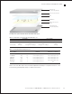
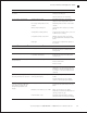
Table 13.1. Placement of cassettes in the Trans-Blot Turbo cell.
Acceptable Unacceptable
Option 1 Option 2 Option 1 Option 2
Upper bay (A) 1 mini gel 2 mini gels -or- 1 midi gel 1 mini gel 2 mini gels -or- 1 midi gel
-and/or- -and/or- -and- -and-
Lower bay (B) 1 mini gel 2 mini gels -or- 1 midi gel 2 mini gels -or- 1 midi gel 1 mini gel
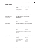
Table 13.2. Trans-Blot Turbo transfer protocols.
Protocol Name
MW, kD Time, Min
1 Mini Gel
2 Mini Gels or 1 Midi Gel
STANDARD SD Any 30 Up to 1.0 A, 25 V constant Up to 1.0 A, 25 V constant
1.5 MM GEL Any 10 2.5 A constant, up to 25 V 1.3 A constant, up to 25 V
HIGH MW >150 10 2.5 A constant, up to 25 V 1.3 A constant, up to 25 V
LOW MW <30 5 2.5 A constant, up to 25 V 1.3 A constant, up to 25 V
MIXED MW 5 –150 7 2.5 A constant, up to 25 V 1.3 A constant, up to 25 V
1 Mini TGX 5–150 3 2.5 A constant, up to 25 V N/A
Refer to the Trans-Blot Turbo Instruction Manual (bulletin 10020688) for complete instructions or the
Protein Blotting Guide (bulletin 2895) for additional information.
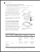
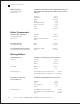
Top ion reservoir stack
Gel
Cassette top
(–) electrode (cathode)
Membrane
Cassette bottom
(+) electrode (anode)
Bottom ion reservoir
stack
Assembly of the gel blot sandwich with the Trans-Blot Turbo system.
Instruction Manual and Application Guide