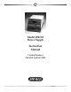
Model 200/2.0 Power Supply Instruction Manual Catalog Numbers 165-4761 and 165-4762 For Technical Service Call Your Local Bio-Rad Office or in the U.S.
Table of Contents Page Section 1 General Information....................................................................................1 1.1 1.2 1.3 1.4 1.5 General Information ...................................................................................................1 Safety ..........................................................................................................................1 Specifications ...................................................................................
Note To insure best performance from the Model 200/2.0 Power Supply, become fully acquainted with these operating instructions before use. Model Catalog No. Date of Delivery Warranty Period Serial No. Invoice No. Purchase Order No. Warranty Bio-Rad Laboratories warrants the Model 200/2.0 Power Supply against defects in materials and workmanship for 1 year. If any defects occur in the instrument during this warranty period, Bio-Rad Laboratories will repair or replace the defective parts free.
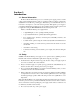
Section 1 Introduction 1.1 General Information Bio-Rad’s Model 200/2.0 microprocessor controlled power supply provides constant voltage to dual output jacks under a variety of operating conditions. Voltage is continuously adjustable from 5 to 200 volts, producing up to 200 watts of power. Current limits can be set from 0.01 to 2.0 amperes to control the current generated.
1.3 Specifications Output voltage 5-200 volts DC, continuously adjustable Output current 0.01-2.0 A, continuously adjustable Output terminals Floating dual output jacks in parallel Set limits Current: Power: 0.01-2.0 A, 0.01 A steps, fully adjustable 200 watts maximum output Automatic crossover upon reaching limit. Timer control 0.1-99.9 hours, 0.1 H steps, continuously adjustable Set point resolution Voltage: Current limit: Time set: ± 1 V, 5-200 VDC ± .01 A, .01-2.0 A + 0.1 H, 0.1-99.
1.4 Diagram of Front Panel Membrane Control Pad 1.5 Description of Membrane Control Pad 1. LED display Displays the current limit, voltage, and timer parameters while they are being set. Displays the operating parameters of current, current limit, voltage, time, load resistance, power output, and volt-hours during a run. 2. Mode indicator lights When a function button is pressed, the indicator light above it will illuminate, indicating that the LED is displaying that parameter.
Section 2 Operation 2.1 Standard Mode Operation General Application: The standard mode is used in blotting applications and in nucleic acid electrophoresis experiments where timing the run is not important. In this mode, the supply is programmed to run at constant voltage within set current limits. Set the Current Limit 1. Press LIMIT. The red indicator light above the button should be on. The LED should read 2.00. 2. Press and hold LOWER.
Turn the Power Supply Off There are three different ways to turn the power supply off. 1. Press VOLTS. The red indicator light should be on. Press LOWER until the LED display reads OFF. Using this method preserves the volt-hour reading until the voltage is reset, but resets all of the other functions to their default values. 2. An alternative method to turn the power supply off is to press VOLTS. The red indicator light should be on. Press RAISE and LOWER simultaneously. The LED will display OFF.
3. Press LIMIT to view the set current limit. The red indicator light above the button should be on, and the set limit will be shown on the LED display. To adjust the current limit, follow the procedure in Section 2.1. 4. Press TIMER to view the remaining time on the timer. The red indicator light above the button should be on, and the time remaining will be shown on the LED display. To change the time remaining for the run, follow the steps detailed in Section 2.2, item 2. 5.
8. Sponge pads can not dissipate heat as effectively as Scoth Brite® gel pads. For high power, high intensity applications, it is advisable to use gel pads in place of sponge pads to minimize localized heating effects. 9. Do not increase voltage settings beyond those indicated in Table 1 for overnight operation. If overnight transfers at low voltages are ineffective for your application and you must increase the voltage, you must also decrease the transfer time and/or provide external cooling. Table 1.
Section 4 Troubleshooting Guide Condition 1. With the power supply on, the LED fails to illuminate. Cause 1a. Power cord is not properly connected. Remedy 1a. Check connections. 1b. The fuse has blown. 1b. Replace fuse. 2. With the power supply on, and the current limit and voltage set, there is not current registered when AMPS is pressed. 2a. The electrophoresis cell (load) is not connected 2a. Check the electrophoresis cell for circuit interruption. 3.
Bio-Rad Laboratories Life Science Group 2000 Alfred Nobel Drive Hercules, California 94547 Telephone (510) 741-1000 Fax: (510) 741-1060 Eastern Regional Office, 85A Marcus Dr., Melville, New York 11747 • Phone (516) 756-2575 • Fax (516) 756-2594 Australia, Bio-Rad Laboratories Pty Limited, Unit 11, 112-118 Talavera Rd P.O. Box 371, North Ryde, NSW 2113 • Phone 02-805-5000 • Fax 02-805-1920 Austria, Bio-Rad Laboratories Ges.m.b.H.