Link Load Prog View AUTO ZERO Edit Clea Prog rO Even off 0 ts: 2 on / Hold Run 0 1 1 2 SCAN 6 Signa [ au l 1 ] Tim e (min) 7 3 8 Signa [ au l 2 ] Setup 1 (nm ) 4 9 5 2 (nm ) GLP 0 BioLogic Q uad T ec ™ UV/VIS Detector Instruction Manual
SAFETY SAFETY ! Caution/Warning Disconnect the QuadTec’s power cable from its power source before servicing. Refer to Chapter 5, Maintenance, for instructions on servicing the BioLogic QuadTec system. The BioLogic QuadTec UV/Vis detector is certified to meet the I.E.C. 1010-1* standard for safety of laboratory equipment. Certified products are safe to use when operated in accordance with the instruction manual.
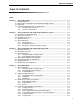
TABLE OF CONTENTS TABLE OF CONTENTS Safety Chapter 1 1.1 1.2 1.3 1.4 General Description .................................................................................................. Using this Manual........................................................................................................ Optical Path of the QuadTec UV/Vis Multi-wavelength Detector ................................ Unpacking ...............................................................................................
TABLE OF CONTENTS 4.5 Scanning UV Spectra.................................................................................................. 4.5.1 Scan Menu ..................................................................................................... 4.5.2 Scan Auto-Zero .............................................................................................. 4.5.3 Performing Wavelength Scans ....................................................................... 4.5.4 Output of Scan Data .....
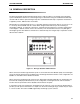
SYSTEM OVERVIEW INTRODUCTION 1.0 GENERAL DESCRIPTION The BioLogic QuadTec multi-wavelength UV/Vis detector adds versatility to your biologic chromatography system. The QuadTec detector has a wavelength range of 190–370 nm using the standard deuterium lamp and 370–740 nm with the optional halogen lamp. The standard deuterium lamp is required for the detection of peptides, proteins, DNA and other nucleotides.
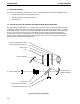
INTRODUCTION SYSTEM OVERVIEW 1.1 USING THIS MANUAL The instructions provided in this manual are for use of the QuadTec Detector with the following systems: • The BioLogic DuoFlow chromatography system • The BioLogic HR chromatography system • Stand-alone use 1.2 OPTICAL PATH OF THE QUADTEC UV/VIS MULTI-WAVELENGTH DETECTOR The light emitted from the lamp [1] is focussed by a lens [2] and a slit [4].
SYSTEM OVERVIEW INTRODUCTION 1.3 UNPACKING When you receive the QuadTec detector and system accessory kit, carefully inspect the shipping containers for any damage, which may have occurred in shipping. Severe damage to a container may indicate damage to its contents. If you suspect damage to the contents, immediately file a claim with the carrier in accordance with their instructions. If necessary, contact your local Bio-Rad office or Bio-Rad technical support at 1-800-4-BIORAD.
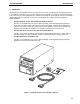
INTRODUCTION SYSTEM OVERVIEW 1.4 PREPARING THE QUADTEC DETECTOR FOR OPERATION 1.4.1 Installation of the Flow Cell The QuadTec detector is shipped with a “dummy” flow cell installed. Before operating the detector, you need to install the biocompatible 3 mm PEEK flow cell. Refer to Figure 1-4 and the procedure below. 1. Make sure the detector power is OFF. 2. Loosen the two knurled screws on the front of the flow cell and gently pull them out. This allows the flow cell housing to slide out. 3.
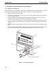
SYSTEM OVERVIEW INTRODUCTION 1.4.2 Power Up and Self-Test The QuadTec detector is equipped with a universal power supply, which operates with supply voltages from 90 to 260 Volts AC. A manual setting of the supply voltage is not required. Caution! system. Make sure to use a properly grounded power outlet and the power cable provided with the Before connecting the QuadTec to the Biologic DuoFlow or BioLogic HR system, perform the following operation: 1.
SYSTEM INSTALLATION AND SETUP USE WITH THE BIOLOGIC DUO-FLOW SYSTEM 2.0 USING THE QUADTEC WITH THE BIOLOGIC DUOFLOW SYSTEM The QuadTec UV/Vis detector provides a powerful addition to the analytical capabilities of the BioLogic DuoFlow system. An instrument communication module (ICM) provided with the detector permits complete programming and control by the BioLogic DuoFlow software version 3.0 or greater.
USE WITH THE BIOLOGIC DUO-FLOW SYSTEM SYSTEM INSTALLATION AND SETUP 2.1 INSTRUMENT CONTROL MODULE (ICM): FOR USE WITH THE DUOFLOW ONLY The ICM translates the signal from the QuadTec detector and transmits it to the BioLogic DuoFlow workstation. The ICM contains the following: Front View • Address setting: The dial should always be set to position 1 • Instrument bus connector: This connector is for System Cable 17 which connects to the BioLogic Workstation and the Model 2128 Fraction Collector if used.
SYSTEM INSTALLATION AND SETUP USE WITH THE BIOLOGIC DUO-FLOW SYSTEM 2.2 ELECTRICAL CONNECTIONS TO THE DUOFLOW SYSTEM The QuadTec communicates with the BioLogic DuoFlow system via the ICM module. To connect the QuadTec to the DuoFlow system: 1. Use System Cable 25 to connect from the RS232 connector on the back of the QuadTec to the COMM connector on the ICM module. 2. Use System Cable 26, the ICM power cord, to connect to the back of the workstation. 3.
USE WITH THE BIOLOGIC DUO-FLOW SYSTEM SYSTEM INSTALLATION AND SETUP 2.3 PLUMBING CONNECTIONS TO THE DUOFLOW SYSTEM The QuadTec has a PEEK flow cell that must be installed by the user. The detector fittings which have been provided are standard HPLC 10-32 fingertight fittings. The BioLogic system uses 1/4-28 fittings. To plumb the QuadTec to the BioLogic DuoFlow system: • Plumb the detector after the column and before the conductivity monitor with the orange or green PEEK tubing provided with the DuoFlow.
SYSTEM INSTALLATION AND SETUP USE WITH THE BIOLOGIC DUO-FLOW SYSTEM 2.4 SYSTEM POWER UP To power up the QuadTec Detector with the BioLogic DuoFlow system: 1. Important: Ensure that the BioLogic DuoFlow software application is not running. 2. Turn on power to the DuoFlow workstation. The ICM power LED should light, since it receives power from the workstation. If it doesn’t, ensure that the ICM power cable is connected to the workstation. 3.
USE WITH THE BIOLOGIC DUOFLOW SYSTEM SYSTEM INSTALLATION AND SETUP BioLogic Duo-Flow - - - View Utilities Options Window Help File New 1 2 New Edit Method Method Run Browser Report Gradient pump: F-10 100 % 0 % Start Tube: Inlet B: High limit: Low limit: psi 1000 psi 0 Run Notes PostRun Fraction size: 1.
SYSTEM INSTALLATION AND SETUP USE WITH THE BIOLOGIC DUO-FLOW SYSTEM The traces shown on the Manual screen chromatogram and printed report are chosen in the Chromatogram Settings window, shown in Figure 2-6. From the system toolbar, select the Settings button to display the Manual screen Chromatogram Settings window. Select the traces from the Trace Device drop-down menu. Select up to eight traces. Select the Visible checkbox to indicate whether or not the trace is to be visible on the screen.
USE WITH THE BIOLOGIC DUO-FLOW SYSTEM SYSTEM INSTALLATION AND SETUP 2.5.2 Setup Editor Screen The Setup screen selects devices to be included in a method. BioLogic DuoFlow software versions 3.0 and later includes the QuadTec Detector. Use the Detectors button in the Setup screen to display the Edit Detector window. Select the QuadTec button and enter the desired wavelengths for your method. The Time Constant value smooths the signal with a time filter.
SYSTEM INSTALLATION AND SETUP USE WITH THE BIOLOGIC DUO-FLOW SYSTEM BioLogic Duo-Flow - - - - Window File View Utilities Options Help New Edit Method Method Frac. Collector 1 2 New Run Browser Report wash load Manual Setup Protocol Notes PostRun Run Log Abort Pause QuadTec-1 (280 nm) Hold Full View Conductivity Fractions Advance Divert Valve Collect 0.0400 100% Buffer B 4000.0 0.0350 3500.0 0.0300 3000.0 0.0250 2500.0 0.
SYSTEM INSTALLATION AND SETUP USE WITH THE BIOLOGIC HR SYSTEM 3.0 USING THE QUADTEC WITH THE BIOLOGIC HR SYSTEM The QuadTec UV/Vis detector provides a powerful addition to the analytical capabilities of the BioLogic HR system. The QuadTec can simultaneously monitor two different wavelengths when connected to the BioLogic HR via two SIM-HR modules. UNO Q-1 COLUMN AV7-3 INJECT VALVE SIM MODULES QUADTEC DETECTOR CONTROLLER WORKSTATION MODEL 2128 FRACTION COLLECTOR Figure 3-1.
USE WITH THE BIOLOGIC HR SYSTEM SYSTEM INSTALLATION AND SETUP 3.1 ELECTRICAL CONNECTIONS TO THE BIOLOGIC HR SYSTEM Set up the BioLogic HR system with the QuadTec detector on the bottom tray. Do not turn power on. 1. Connect one SIM-HR to the HR Workstation with System Cable 17, and ensure that the SIM’s device address number (Device Number) is set to 1. 2. "Daisy-chain" a second SIM-HR to the first SIM-HR using a second System Cable 17.
SYSTEM INSTALLATION AND SETUP USE WITH THE BIOLOGIC HR SYSTEM 3.2 PLUMBING CONNECTIONS TO THE BIOLOGIC HR SYSTEM After making all the cable connections make the plumbing connections, as shown in Figure 3-3. WASTE V7-3 or AV7-3 INJECT VALVE 2 CHART RECORDER 1 3 WORKSTATION COLUMN 7 6 4 5 INSTRUMENT BUS A B WASTE INJECT PORT RINSE QUADTEC DETECTOR CONDUCTIVITY MONITOR BUFFER A and B CONTROLLER AND COLOR MONITOR COLLECT TO MODEL 2128 FRACTION COLLECTOR Figure 3-3.
USE WITH THE BIOLOGIC HR SYSTEM SYSTEM INSTALLATION AND SETUP 3.3.2 Changing Operating Parameters To change any parameter value: 1. Use the green arrow keys to move the blinking cursor to the desired position on the display. 2. Press the numeric keys to enter or change values. Important: Confirm and leave this position by pressing any arrow key. Input is disabled automatically if a time limit of 60 seconds is reached without pressing any key, and the screen returns to the main menu.
SYSTEM INSTALLATION AND SETUP USE WITH THE BIOLOGIC HR SYSTEM 2. Configure SIM 1 and 2 “Units” value for the desired wavelengths (e.g., AU 280 nm and AU 260 nm.) Unit Range, Minimum = 0 Unit Range, Maximum = 2 Device Output Range (Volts), Minimum = 0 Device Output Range (Volts), Maximum = 1 3. The Device Output Voltage maximum should be set to 1 V, which is the output from the QuadTec Detector integrator outputs. 4. From the Options drop-down menu in the Manual Screen, select Chromatogram Settings.
USE WITH THE BIOLOGIC HR SYSTEM SYSTEM INSTALLATION AND SETUP AUTO CALIBRATION From Time Constant, press the green Right arrow to move to this field. Pressing the green Up arrow starts the procedure for the calibration of the wavelength scale. It searches automatically for reference points within the spectra of the lamp for reliability and reproducibility of the wavelength. The points used for calibration are the zero order reflection of the grating (000 nm) and the Ha spectral line of Deuterium (656 nm).
SYSTEM INSTALLATION AND SETUP USE AS A STAND-ALONE SYSTEM 4.0 STAND-ALONE MODE Turn on power to the QuadTec detector and wait while it completes its self test. If successful, the lamp will warm to a constant working temperature. During warm up, the display shows HEA in the lower left position. The initialization routine is completed by an automatic calibration procedure, and the device is ready for operation when ON is shown in the lower left position. 4.1 SYSTEM OPERATION IN STAND-ALONE MODE 4.1.
USE AS A STAND-ALONE SYSTEM SYSTEM INSTALLATION AND SETUP 4.2 DISPLAY AND MENU STRUCTURE After the QuadTec has been switched on and the self-test routine has been successfully run, the device is ready for operation and the main menu or operation screen will be displayed. Load Prog LINK Menu Link VIEW Menu View Edit Prog Clear 0 Events: 2 off 0 on / Signal 1 [ au ] Signal 2 [ au ] Setup GLP Hold 0 Run 1 Time (min) 1 (nm) SETUP Menu GLP Menu 2 (nm) Figure 4-1.
SYSTEM INSTALLATION AND SETUP USE AS A STAND-ALONE SYSTEM AUTO CALIBRATION This procedure searches automatically for reference points within the spectra of the lamp for reliability and reproducibility of the wavelength. The points used for calibration are the zero order reflection of the grating (000 nm) and the Ha spectral line of deuterium (656 nm). Auto calibration is performed automatically when power to the detector is switched on.
USE AS A STAND-ALONE SYSTEM ANALOG OUT FULL SCALE SYSTEM INSTALLATION AND SETUP Absorbance signals come from the two integrator outputs on the rear of the detector and may be scaled. Full scale may be set from 0.0001 to 10 AU (in 16 steps) using the Up/Down arrow keys. The maximum output voltage may be set to 0.1, 1, and 10 V. Load Prog Edit Prog Clear 0 Events: 2 off 0 on / Signal 1 [ au ] Signal 2 [ au ] Link Setup View GLP Hold 0 Run 1 Time (min) 1 (nm) 2 (nm) Figure 4-4.
SYSTEM INSTALLATION AND SETUP USE AS A STAND-ALONE SYSTEM Use the Right arrow key to access the output field and select E1 or E2 as appropriate. Use the right arrow key to access the signal level. Set the minimum signal level that must be exceeded before fraction collection starts. Both functions, level and event, are evaluated in a timetable to control fraction collection.
USE AS A STAND-ALONE SYSTEM SYSTEM INSTALLATION AND SETUP 4.2.3 VIEW Menu The View menu gives an overview of existing programs and program links. The following figure shows an example where programs 01, 02, 03, 04, and 11 and link 21 have been defined. Link View Figure 4-7. Overview of the View Menu 4.
SYSTEM INSTALLATION AND SETUP USE AS A STAND-ALONE SYSTEM 4.3.1 Selecting Wavelength(s) Use the green Left arrow to select the View menu and then: 1. Position the cursor on one of the two wavelength fields and select the wavelength by entering the desired values with the numeric keys. If you want to use one single wavelength, enter a zero in the unused fields. Entering zero deactivates the respective wavelength. 2.
USE AS A STAND-ALONE SYSTEM SYSTEM INSTALLATION AND SETUP 4.4 PROGRAMMING THE QUADTEC UV/Vis DETECTOR 4.4.1 Creating Programs When creating programs, note the following: • The QuadTec can store up to 20 programs. By moving the cursor to the VIEW menu, you can check the availability and allocation of program numbers. • All programs are saved permanently until overwritten. • Time displays are given in minutes with decimal calculation of seconds, i. e. 0.3 min = 18 s.
SYSTEM INSTALLATION AND SETUP USE AS A STAND-ALONE SYSTEM 4.4.3 Time Programming of Absorption Wavelengths Use this instruction for programming the absorption wavelengths as a function of time. 1. Access the Operation/Main menu screen. 2. Move cursor to the field “Edit Prog” and select a number (1 to 20) for the new program. 3. Press any arrow key to confirm and enter Edit mode for the new program. 4. The cursor is automatically moved to Time 000.0, which is the fixed start time. 5.
USE AS A STAND-ALONE SYSTEM SYSTEM INSTALLATION AND SETUP 4.4.4 Programming Events for Control of a Fraction Collector This example demonstrates a program to control a fraction collector via the QuadTec UV/Vis detector event output using signal level and a defined time window. 1. Enter the Setup menu and proceed to the window Fraction. 2. Enter the desired value for the signal level, e.g. 0.32 AU, the delay volume if needed, and select E1 for relay output. 3. Return to the operation screen 4.
SYSTEM INSTALLATION AND SETUP USE AS A STAND-ALONE SYSTEM 4.4.5 Program Execution Programs must be activated prior to execution. To execute a program: 1. Enter the desired program number in the “Load Prog” field and confirm by pressing an arrow key. The detector settings are adjusted to all presets of that program. 2. An autozero is performed automatically every time a new program is loaded. 3.
USE AS A STAND-ALONE SYSTEM SYSTEM INSTALLATION AND SETUP 3. In the LINK menu, the momentary status of the running link is shown. To access this menu move the cursor to the “Load Prog” field and press the Left arrow. 4. To return from the LINK menu press the Right arrow. To delete a program or a link, it has to be loaded first and then: 1. Entering 0 in the Edit Prog and pressing an arrow key will produce the message “Delete this program? Confirm by cursor”.
SYSTEM INSTALLATION AND SETUP USE AS A STAND-ALONE SYSTEM The number of the scan to be performed or given out is selected by moving the cursor to the scan number, (e.g. no.:1 with the Right arrow.) The scan number can be changed using the Up/Down arrows.
USE AS A STAND-ALONE SYSTEM SYSTEM INSTALLATION AND SETUP 4.6 QUADTEC DETECTOR WAKE-UP PROGRAM Program # 30 is reserved for the Wake-Up function, enabling the lamp to be turned on or to preset a wavelength program time or date. For example, if the lamp was switched off overnight, the Wake-Up function can be used to switch on and preheat it the next day.
SYSTEM INSTALLATION AND SETUP USE AS A STAND-ALONE SYSTEM 4.8 CONNECTING OTHER INSTRUMENTS TO THE QUADTEC DETECTOR 4.8.1 Using the Event and Remote Connectors Located on the rear of the QuadTec detector are two electrical connectors (Event and Remote) that serve to send or receive signals from other instruments. The Event and Remote interfaces are controlled by programs or the SETUP menu.
SYSTEM INSTALLATION AND SETUP MAINTENANCE 5.0 MAINTENANCE 5.1 CHECKING THE STATUS OF THE DEUTERIUM LAMP The deuterium lamp used with the QuadTec has an extended life time to ensure long-time functionality and reliable measurements with low noise and baseline drift as well as high sensitivity. The lifetime of the lamp depends on different factors, like the number of lamp starts, average burning time, and user requirements for noise and sensitivity.
MAINTENANCE SYSTEM INSTALLATION AND SETUP 5.2 CHANGING THE LAMP 1. Let the lamp cool down for at least 15 minutes after switching it off. Caution: Remove the power plug before opening the QuadTec case. 2. Unscrew the six screws around the base of the detector housing and remove it by lifting. 3. The lamp is located in a black housing on the right side of the instrument. The Deuterium lamp is shown in Figure 5-1; the Halogen lamp is shown in Figure 5-2. 4.
SYSTEM INSTALLATION AND SETUP Link Load Prog View AUTO ZER O Edit Cle Prog ar O Even off 0 ts: 2 on / Hol Rund 0 1 1 2 SCA N 6 Sign al [ au 1 ] Tim (mine ) 7 3 8 Sign al [ au 2 ] Setu 1 (nm ) 4 9 5 MAINTENANCE p 2 (nm ) GLP 0 Figure 5-2. Replacing a Halogen Lamp 6. Insert the lamp’s electrical supply cable connector into the appropriate socket. The deuterium lamp has a three-pole plug, the halogen lamp a two-pole one.
MAINTENANCE SYSTEM INSTALLATION AND SETUP 3. From the Extended Setup menu, press the Down arrow to access the desired menu items. Make the following modifications: a. LAMP: The lamp type is specified using the Up arrow to toggle between deuterium and halogen. Changing the lamp type prompts a question on whether to reset the lamps’ working time. Pressing any green arrow key will reset the time. The lamp number is incremented automatically and cannot be edited.
SYSTEM INSTALLATION AND SETUP TROUBLESHOOTING 6.0 TROUBLESHOOTING Problem Possible Cause QuadTec detector faceplate does not show up in BioLogic DuoFlow software Manual screen. Communications problem between the QuadTec Instrument Control Module and the DuoFlow Controller software Suggested Solutions 1. In the DuoFlow Manual screen, click on the detector faceplate toggle button to switch between QuadTec and optics module faceplates. 2.
TROUBLESHOOTING SYSTEM INSTALLATION AND SETUP Problem Possible Cause Wavelengths chosen in the Setup editor detector devices box do not show up on the Run screen chromatogram. Software options are not configured appropriately. 1. Click on the Run screen Settings button to choose which traces are visible. 2. Zero the baseline as appropriate. 3. Re-scale the chromatogram traces using the scroll bars as appropriate. No traces are seen on the Manual screen or Run screen chromatogram.
SYSTEM INSTALLATION AND SETUP TROUBLESHOOTING Problem Possible Cause Suggested Solutions Excessive pump pulsations exhibited as a sinusoidal baseline or “regular noise” on the detector baseline. Air bubbles trapped in the pump heads can produce exaggerated pulsation, which appear as a noisy baseline. 1. Purge the pump heads to remove trapped air bubbles. See the Troubleshooting section of the BioLogic DuoFlow instruction manual.
TROUBLESHOOTING SYSTEM INSTALLATION AND SETUP Problem Possible Cause Negative peaks. The sample is applied to the column in a different buffer from that used to equilibrate and elute the column. Refractive index changes may be responsible for the negative peaks. 1. Apply the sample in the same buffer used to equilibrate the column. The elution buffer may have a higher UV absorbance than the sample components. 2. Check the elution buffer’s UV absorbance.
APPENDIX A SPECIFICATIONS APPENDIX A SPECIFICATIONS Lamp type Deuterium (standard) Halogen (option) User-replaceable Wavelength range 190–740 nm with deuterium lamp, automatic edge filter used at 380 nm 370–740 nm with halogen lamp No. of simultaneous wavelengths 4 with Biologic DuoFlow system 2 with Biologic HR system 2 in stand-alone mode Bandwidth 8 nm Wavelength accuracy 1 nm Measurement range 0–4 AU Sensitivity 2 x 10⁻⁵ AU at 240 nm and time constant 1.
APPENDIX B WAVELENGTH SELECTION APPENDIX B WAVELENGTH SELECTION FOR TYPICAL BIOLOGICAL MOLECULES Wavelength Absorbing Species Applications Comments 206 nm Carboxyl groups, ester links, amide or peptide bonds Proteins, peptides, amino acids, steroids, nucleotides, fatty acids, carbohydrates Virtually all biological macromolecules will absorb at this wavelength. Detection at this wavelength will give high sensitivity and/or permit the detection of compounds that don’t absorb at other wavelengths.
APPENDIX C ORDERING INFORMATION APPENDIX C ORDERING INFORMATION. SPARE PARTS AND ACCESSORIES 760-1300 QuadTec DuoFlow Detector Kit; 100/110 V; 200/240 V Includes QuadTec Detector, 3 mm flowcell, System Cable 25 RS232 null modem cable, 4 x 10-32 Fingertight fittings and QuadTec Accessory kit for the DuoFlow. This accessory kit includes Instrument Control Module (ICM), System Cable 26 ICM power cable, System Cable 17 BioLogic communication cable, DuoFlow software version 3.
Bio-Rad Laboratories, Inc. Web site www.bio-rad.