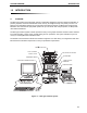
BioFrac Franction Collector F1 A F2 F3 F4 F5 1 2 3 4 5 6 7 8 9 0 B VALVE A VALVE B B IO L OGIC D UO F LOW™ CHROMATOGRAPHY SYSTEM INSTRUCTION MANUAL (BioLogic DuoFlow™ Software Version 5.0) Copyright © (2003) Bio-Rad Laboratories, Inc. All rights reserved.
TABLE OF CONTENTS TABLE OF CONTENTS SAFETY SECTION 1. Chapter 1.0 1.1 1.2 1.3 1.4 1.5 SYSTEM OVERVIEW Introduction ...............................................................................................................1-1 Overview .....................................................................................................................1-1 Features ......................................................................................................................1-2 Unpacking ........
TABLE OF CONTENTS 2.9.8 Model 1327 Chart Recorder...........................................................................2-52 2.9.9 Generic Chart Recorders ...............................................................................2-52 2.9.10 Uninterruptible Power Supply.........................................................................2-53 2.9.11 Printers ...........................................................................................................2-53 2.
TABLE OF CONTENTS SECTION 3. SYSTEM OPERATION Chapter 5.0 5.1 5.2 5.3 Introduction to the System Software ......................................................................5-1 System Interface .........................................................................................................5-1 Standard Mouse and Keyboard Functions .................................................................5-2 System Menus ..................................................................................
TABLE OF CONTENTS Chapter 10.0 Buffer Blending .........................................................................................................10-1 10.1 Doubled Flow Rate Capacity Using a Maximizer .......................................................10-1 10.2 Buffer Blending with the Maximizer.............................................................................10-2 10.3 pH Measurement and Corrections ..............................................................................
TABLE OF CONTENTS LIST OF FIGURES 1-1. 2-1. 2-2. 2-3. 2-4. 2-5. 2-6. 2-7. 2-8. 2-9. 2-10. 2-11. 2-12. 2-13. 2-14. 2-15. 2-16. 2-17. 2-18. 2-19. 2-20. 2-21. 2-22. 2-23. 2-24. 2-25. 2-26. 2-27. 2-28. 2-29. 2-30. 2-31. 3-1. 3-2. 3-3. 3-4. 3-5. 3-6. 3-7. 3-8. 3-9. 3-10. 3-11. 3-12. 3-13. 3-14. 3-15. 3-16. 3-17. 3-18. 3-19. 4-1. 4-2. 4-3. 4-4. BioLogic DuoFlow System .......................................................................................................
TABLE OF CONTENTS 4-5. 4-6. 4-7. 5-1. 6-1. 6-2. 6-3. 6-4. 6-5. 6-6. 6-7. 6-8. 6-9. 7-1. 7-2. 7-3. 7-4. 7-5. 7-6. 7-7. 7-8. 7-9. 7-10. 7-11. 7-12. 7-13. 7-14. 7-15. 7-16. 8-1. 8-2. 8-3. 8-4. 8-5. 8-6. 9-1. 9-2. 9-3. 10-1. 10-2. 11-1. 11-2. 11-3. 11-4. 11-5. 11-6. 11-7. 11-8. 11-9. viii Plumbing Connections to the Workstation Pump ....................................................................4-5 Inject Valve Plumbing for an AVR7-3 ......................................................................
TABLE OF CONTENTS LIST OF TABLES 1-1. 2-1. 2-2. 2-3. 2-4. 2-5. 2-6. 2-7. 2-8. 2-9. 2-10. 2-11. 2-12. 2-13. 2-14. 2-15. 3-1. 4-1. 5-1. 5-2. 5-3. 5-4. 5-5. 5-6. 5-7. 5-8. 6-1. 6-2. 6-3. 6-4. 6-5. 6-6. 7-1. 7-2. 7-3. 7-4. 7-5. 7-6. 7-7. 7-8. 7-9. 7-10. 7-11. 7-12. 7-13. 9-1. 10-1. B-1. DuoFlow System Configurations..............................................................................................1-4 Front View of the Dell PC Computer as the DuoFlow Controller.......................................
SYSTEM OVERVIEW INTRODUCTION 1.0 INTRODUCTION 1.1 OVERVIEW The BioLogic DuoFlow chromatography system is specifically designed for the high resolution purification of proteins, peptides, and other biomolecules where recovery of biological activity is of primary concern. The DuoFlow F10 pumphead operates at up to 20 ml/min and 3500 psi (233 bar, 23 MPa) when used with the Maximizer. The DuoFlow F40 pumphead operates at up to 80 ml/min and 1000 psi (66 bar, 6.6 MPa) when used with the Maximizer.
INTRODUCTION 1.2 SYSTEM OVERVIEW FEATURES BioLogic DuoFlow systems provide the following features: 1-2 • Setup Flexibility. A space saving modular design that is stackable and easily configured to meet your exact needs and fit into your desired bench space. Trays and vertical bars are moveable and removable. Horizontal bars can be placed in the optimal position for valves, columns, detectors, etc. The system fits easily into a cold box.
SYSTEM OVERVIEW • 1.3 INTRODUCTION Third party detectors, such as refractive index or fluorescence, may be utilized with the DuoFlow systems via a Signal Import Module (SIM) or Maximizer. • Conductivity Monitor. Monitors salt concentration to assure reliable gradient formation and pump function. • Fraction Collection. The DuoFlow system supports a wide variety of fraction collection options including: Collect All, Threshold Collection, Collection Windows and Threshold & Collection Windows.
INTRODUCTION 1.
SYSTEM OVERVIEW 1.5 INTRODUCTION QUICK START PROCEDURE The general procedure used to create and run a chromatography experiment on a DuoFlow system is described below. 1. Install the required devices and instruments on the system (see Figures 3-4 and 5-5 for cable connections and 4-1 and 4-3 for plumbing connections). 2. Flush all plumbing with DDI H2O to ensure that the system is clean and free of air and then prime the pumps with starting buffer. See Chapter 4 for more detail. 3.
SYSTEM OVERVIEW 2.0 DESCRIPTION OF SYSTEM COMPONENTS DESCRIPTION OF SYSTEM COMPONENTS The DuoFlow’s modular design supports many types of system components, and allows for a wide variety of system configurations. This section discusses in detail the function of each component and its connection to the system. • Dell PC Computer/Controller and USB Bitbus Communicator (Section 2.1) • Workstation (Section 2.2) • Maximizer (Section 2.3) • Mixers: MX-1 and Maximizer mixers: (Section 2.
DESCRIPTION OF BIOLOGIC DUOFLOW SYSTEM 2.1 SYSTEM OVERVIEW CONTROLLER AND USB BITBUS COMMUNICATOR The DuoFlow system is controlled by a PC computer, referred to throughout this document as the Controller. The Dell Controller available from Bio-Rad includes a color display monitor, a keyboard, a mouse device, a CD-ROM drive, and a floppy disk drive. The Controller communicates with the workstation and other external devices through its USB connector.
SYSTEM OVERVIEW DESCRIPTION OF BIOLOGIC DUOFLOW SYSTEM Table 2-1. (continued) Front View of a Dell PC Computer as the DuoFlow Controller Feature Description CD ROM Drive To load updates of the BioLogic DuoFlow operating software. To open the drive, press the button on the front of the drive. Keyboard, Mouse, & Function Keys The keyboard and mouse interface devices control the system. They are standard PC compatible input devices.
DESCRIPTION OF BIOLOGIC DUOFLOW SYSTEM SYSTEM OVERVIEW Table 2-2.
SYSTEM OVERVIEW 2.1.2 DESCRIPTION OF BIOLOGIC DUOFLOW SYSTEM USB Bitbus Communicator The USB Bitbus Communicator is used to connect the Controller to DuoFlow system instrument bus and to supply power to the instrument bus when a Signal Import Module (SIM) is used Table 2-3. USB Bitbus Communicator POWER USB PWR SELECT BUS PWR INSTR BUS ON EXT INT +5V FRONT VIEW Feature USB REAR VIEW Description Used to connect to the Controller USB port by way of a USB cable (catalog number 760-2032).
DESCRIPTION OF BIOLOGIC DUOFLOW SYSTEM 2.2 SYSTEM OVERVIEW WORKSTATION The Workstation contains the following: • Dual pumpheads, each consists of two biocompatible dual piston pumpheads. A built-in pressure transducer is located on the workstation at the pump outlet. The pressure transducer measures system pressure, which is displayed on the lower status bar of the software Manual and Run screens. Purge and Pause buttons (Purge A, Purge B, and Pause) are present on the front of the Workstation.
SYSTEM OVERVIEW DESCRIPTION OF BIOLOGIC DUOFLOW SYSTEM Table 2-5. Workstation Front Panel Controls PUMPHEAD WASHOUT INLET PORTS PRIMING PORT A PRESSURE TRANSDUCER INLET PORTS PRESSURE TRANSDUCER OUTLET PORT BioLogic DuoFlow Workstation PUMPHEAD OUTLET PORTS PAUSE PRIMING PORT B ALERT LEDs POWER WASHOUT OUTLET A B INLET PORTS A & B PURGE Feature Description Power Button Turns power on/off to the Workstation and to the components connected to it.
DESCRIPTION OF BIOLOGIC DUOFLOW SYSTEM SYSTEM OVERVIEW Table 2-5. (continued) Workstation Front Panel Controls Description Feature Plumbing Connections Ports on the front of the Workstation: a. Pumphead Inlet ports: Buffer inlet lines attach to the bottom of each pumphead using standard 1/4-28 flat-bottom fittings. The pumphead inlet tubing is 1/8” (3.2 mm) OD, 0.062” (1.6 mm) ID PTFE tubing with flat bottom fittings which are supplied in the Fittings kit. b.
SYSTEM OVERVIEW DESCRIPTION OF BIOLOGIC DUOFLOW SYSTEM 6 UV LAMP Connector 10..25V 2 3 1. INJECT 2. n/c 3. n/c 4. n/c 5. FC ADV 6. AUX PUMP 7. n/c 8. n/c 9. GND INSTR. BUS 5 AUTOMATED VALVES 1 MIXER 4 SOLENOID VALVES Table 2-6. Workstation Rear Panel Connectors UV CHART COND CHART UV OPTICS COND FLOWCELL 0.3A MAX. Description Solenoid Valves: To connect DuoFlow low pressure solenoid valves (SV5-4 and SVT3-2) to the system.
DESCRIPTION OF BIOLOGIC DUOFLOW SYSTEM SYSTEM OVERVIEW Table 2-6. (continued) Workstation Rear Panel Connectors Description Conector UV Chart: For UV signal output to a single or dual pen chart recorder. When the Bio-Rad Model 1327 is used, chart recorder Pen Up/Down, Stop/Start commands, and event marks are sent from this connector. The Bio-Rad Model 1327 dual pen recorder needs an 8-pin mini-DIN to standard DIN cable (System Cable 2) and a mini-DIN to banana plugs cable (System Cable 4).
SYSTEM OVERVIEW 2.3 DESCRIPTION OF BIOLOGIC DUOFLOW SYSTEM BIOLOGIC MAXIMIZER VALVE SYSTEM The Maximizer enables buffer blending applications, doubles the accessible pump flow rate, and doubles valving capacity to 6 low pressure valves and 6 high pressure valves. The Maximizer includes a separate Maximizer mixer (see Section 2.4.2) and pH monitor (see Section 2.5.4).
DESCRIPTION OF BIOLOGIC DUOFLOW SYSTEM SYSTEM OVERVIEW Table 2-7. Maximizer Front Panel Controls LCD DISPLAY VALVES A & B ARROW KEYS VALVE A VALVE B A1 A2 B1 B2 ACID BASE WATER SALT ENTER KEY VALVE INLET SELECT BUTTONS POWER ON/OFF VALVE INLET STATUS LEDs SOFT KEYS Description Feature Power On/Off Controls power to the unit. Valves A & B Proportioning valves used for Buffer Blending and inlet selection. Each valve has two inlet ports and one outlet port.
SYSTEM OVERVIEW DESCRIPTION OF BIOLOGIC DUOFLOW SYSTEM Table 2-7. (continued) Maximizer Front Panel Controls Feature Softkeys Enter and Arrow Keys Description For limited local operation of the Maximizer. This is discussed further in Table 2-9. To operate the Maximizer in conjunction with the softkeys, as discussed above.
DESCRIPTION OF BIOLOGIC DUOFLOW SYSTEM SYSTEM OVERVIEW Table 2-8. Maximizer Rear Panel Connectors SV PORT 7 SV PORT 8 SV PORT 9 AV PORT 10 AV PORT 11 9 GND pH 8 SIM 7 COND 6 AUX PUMP INSTR. BUS 5 FC ADV COM2 4 COM1 3 MIXER 2 1 INJECT 100-240V 2 - 2A MAX 50 - 60 Hz POWER ENTRY AUX PORT AV PORT 12 ATC MAXIMIZER REAR Description Connector Solenoid Valves: To connect DuoFlow low pressure solenoid valves (SV5-4 and SVT3-2) to the system.
SYSTEM OVERVIEW DESCRIPTION OF BIOLOGIC DUOFLOW SYSTEM Table 2-8. (continued) Maximizer Rear Panel Connectors Description Connector Instrument Bus: The RJ-45 modular phone connectors and their bus communication cables connect the Maximizer to the Controller and the Workstation (via the USB Bitbus Communicator). The Instrument Bus handles all communications between the Controller and each of the components in the system. Components can be connected in any order in the system.
DESCRIPTION OF BIOLOGIC DUOFLOW SYSTEM SYSTEM OVERVIEW Table 2-9. Maximizer Screens Function and Description on Maximizer Faceplate in Local Mode Screen Inlet Selection BLEND PREV A POS 0 NEXT BLEND PREV B POS 1 NEXT Arrow buttons switch between Inlets A1(0) and A2(1). PREV changes to previous screen. NEXT changes to next screen. Arrow buttons switch between Inlets B1(0) and B2(1). Valve Control POS 0 PREV NEXT Arrow buttons select a port on valve .
SYSTEM OVERVIEW DESCRIPTION OF BIOLOGIC DUOFLOW SYSTEM Table 2-9. (continued) Maximizer Screens Function and Description Screen pH Calibration (continued) 1ST pH PT. _4.00 CURSOR CANCEL 1ST: CANCEL 35.22 mV SET 2ND pH PT. _7.00 CURSOR CANCEL 2ND: CANCEL 35.22 mV SET CURSOR moves the cursor to the next digit of the pH set point. UP/DOWN arrows adjust the pH set point. CANCEL aborts the calibration. ENTER accepts the pH value of the first calibration buffer and moves to the next screen.
DESCRIPTION OF BIOLOGIC DUOFLOW SYSTEM 2.4 SYSTEM OVERVIEW MIXERS Bio-Rad’s DuoFlow mixers improve gradient quality by mixing the output from the DuoFlow Workstation pumps. There are two PEEK biocompatible mixers for DuoFlow systems. • MX-1 mixer: A low volume mixer for use with a DuoFlow system not equipped with the Maximizer. • Maximizer mixer: A large volume mixer for use with the Maximizer. The mixer cable plugs into the connector labeled Mixer on the rear of the Maximizer or Workstation.
SYSTEM OVERVIEW 2.4.2 DESCRIPTION OF BIOLOGIC DUOFLOW SYSTEM Maximizer Mixer The Maximizer mixer provides the larger capacity required when the Maximizer is used. The Maximizer mixer may be used with or without a mixer barrel: the mixer body, mixer top, and mixer barrel are provided with the system; an optional mixer barrel extender is available. The mixer barrels fit between the mixer body and the mixer top and are used for higher flow rates.
DESCRIPTION OF BIOLOGIC DUOFLOW SYSTEM SYSTEM OVERVIEW 2.4.3 Changing Mixer Capacity Be sure to follow these directions carefully. The mixer may leak if it is assembled incorrectly, or if an O-ring is not correctly placed in the O-ring groove. Note: Flush any hazardous material from the system. Drain fluid from the mixer and disconnect the mixer plumbing and cables. 1.
SYSTEM OVERVIEW 2.5 DESCRIPTION OF BIOLOGIC DUOFLOW SYSTEM DETECTION SYSTEMS The DuoFlow system supports the following detection and monitoring devices: • UV Detector • Conductivity Monitor • QuadTec UV/VIS Detector • pH Monitor 2.5.1 UV Detector The UV detector is a single beam, fixed wavelength UV absorbance detector specifically designed for high resolution protein chromatography. • Available in several configurations.
DESCRIPTION OF BIOLOGIC DUOFLOW SYSTEM SYSTEM OVERVIEW Two flow cells are available with the detector. Both use 1/4-28 flat-bottom fittings. • Analytical 5 mm flow cell. This flow cell is recommended for high resolution detection. This flow cell has a 5 mm path length, a volume of 16 µl, and is rated to 750 psi at flow rates between 0.1 and 10 ml/min.
SYSTEM OVERVIEW 2.5.2 DESCRIPTION OF BIOLOGIC DUOFLOW SYSTEM Conductivity Monitor The Conductivity monitor, included with all DuoFlow systems, measures fluid conductivity to track the accuracy of a salt gradient. This data is useful for optimizing purification protocols and column cleaning procedures. Conductivity monitor sensitivity ranges from 0 to 500 mS/cm.
DESCRIPTION OF BIOLOGIC DUOFLOW SYSTEM SYSTEM OVERVIEW • System Cable 25, RS232. To connect to the Instrument Control Module (ICM). If a Maximizer is in use, connect to its COM1 port instead of the ICM. • Power cord An optional 2 mm PEEK flow cell (2.2 µl flow cell volume, 18 µl including flow cell inlet and outlet tubes) is available for flow rates up to 80 ml/min including 10-32 long Fingertight fittings (quantity 4).
SYSTEM OVERVIEW 2.5.4 DESCRIPTION OF BIOLOGIC DUOFLOW SYSTEM pH Monitor The BioLogic DuoFlow pH monitor enables direct monitoring of pH conditions during a run. The pH monitor is optional for all DuoFlow systems. The pH monitor consists of the following: • Flow cell: The PEEK flow cell has a swept volume of approximately 80 µl when the pH electrode is inserted.
DESCRIPTION OF BIOLOGIC DUOFLOW SYSTEM 2.6 SYSTEM OVERVIEW VALVES BioRad offers an extensive variety of valves that enable greater flexibility for multiple sample and advanced application options. The DuoFlow system controls 3 AVR high pressure valves and 3 SV low pressure valves. DuoFlow systems with a Maximizer double the number of valves to 6 AVR high pressure and 6 SV low pressure valves.
SYSTEM OVERVIEW DESCRIPTION OF BIOLOGIC DUOFLOW SYSTEM The three valve positions are Load (position 1), Inject (position 2), and Purge (position 3). See Figure 2-11. Load is the default position when the system is powered up or at the end of a method run unless configured differently from the Edit User Preferences window, available from the Options menu in the system software.
DESCRIPTION OF BIOLOGIC DUOFLOW SYSTEM SYSTEM OVERVIEW LARGE VOLUME SAMPLE LOADING WORKSTATION PUMP WASTE 6 WASTE 7 5 4 AVR7-3 1 LOW PRESSURE COLUMN 3 2 AUX PUMP PURGE AUX PUMP SAMPLE LOADING AND AFFINITY CHROMATOGRAPHY AVR7-3 VALVE FOR SAMPLE LOADING WORKSTATION PUMP 6 AVR7-3 VALVE AS "CHANGE FLOW" VALVE 5 7 4 INJECT 1 2 6 FORWARD FLOW 3 SAMPLE LOOP COLUMN 5 7 4 1 LOAD SAMPLE INJECT 3 2 WORKSTATION PUMP 6 UV MONITOR & FRACTION COLLECTOR 5 7 LOAD 1 2 4 6 REVERSE FLOW 3 SAM
SYSTEM OVERVIEW 2.6.2 DESCRIPTION OF BIOLOGIC DUOFLOW SYSTEM AVR9-8 Stream Select Valve The AVR9-8 stream select valve is an 9-port 8-position valve. This valve is optional for all DuoFlow systems. The valve is rated at 3500 psi (233 bar) and is designed with non-metallic wetted parts for bio-compatibility and minimal internal dead volumes. • The AVR9-8 is ideal for stream selection, column switching, and large volume fraction collection.
DESCRIPTION OF BIOLOGIC DUOFLOW SYSTEM SYSTEM OVERVIEW Position 1 on the AVR9-8 is the default position when the system is powered up or at the end of a method run unless configured differently from the Edit User Preferences window, available from the Options menu. The valve uses 1/4-28 fittings and 1/16” (1.6 mm) OD PEEK tubing supplied with the fitting kit when plumbing these valves.
SYSTEM OVERVIEW 2.6.3 DESCRIPTION OF BIOLOGIC DUOFLOW SYSTEM SV5-4 Buffer Select and Automated Sample Loading Valve The SV5-4 valve is a low pressure, 5-port, 4-position valve used for automatic buffer selection and sample loading. The SV5-4 valve may be used for: • Buffer and/or sample selection when placed before the Workstation pumps or an auxilary load pump. An SV5-4 valve connected to a Workstation pump inlet enables access to four separate solutions.
DESCRIPTION OF BIOLOGIC DUOFLOW SYSTEM SYSTEM OVERVIEW SV5-4 FOR BUFFER AND SAMPLE LOADING TO COLUMN WORKSTATION A RUNNING BUFFER STORAGE SOLUTION (I.E., 20% ETHANOL) SV5-4 B SAMPLE RUNNING BUFFER SANITIZING SOLUTION (I.E.
SYSTEM OVERVIEW 2.6.4 DESCRIPTION OF SYSTEM COMPONENTS SVT3-2 Diverter Valve The SVT3-2 diverter valve is a low pressure 3-port, 2-position valve. This valve may be used in a number of ways: • To divert the eluant stream from the detectors to a fraction collector or a waste container. • As a sample select valve when placed before Workstation pump A. The Maximizer may not be used in this application. • As a water rinse valve when placed before Workstation pump B.
DESCRIPTION OF SYSTEM COMPONENTS SYSTEM OVERVIEW WORKSTATION UV MONITOR A B SAMPLE SELECT VALVE CONDUCTIVITY FLOW CELL DIVERTER VALVE WATER RINSE VALVE B A SAMPLE WATER RINSE WASTE COLLECT TO MODEL 2110 OR GENERIC FRACTION COLLECTOR Figure 2-18. Two Configurations of the SVT3-2 Valve When used as a diverter valve with a Model 2110 or generic fraction collector, this valve should be named as such from the Setup screen. Position 1 of this valve is Waste; position 2, Collect.
SYSTEM OVERVIEW DESCRIPTION OF SYSTEM COMPONENTS 2.7 FRACTION COLLECTORS The DuoFlow features several options for fraction collection: • BioFrac fraction collector • Model 2110 fraction collector • Model 2128 fraction collector • Non-Bio-rad fraction collectors The BioFrac fraction collector, the Model 2110 fraction collector, and the Model 2128 fraction collector are programmable and can be run via BioLogic software version 4.0 or higher. 2.7.
DESCRIPTION OF SYSTEM COMPONENTS • SYSTEM OVERVIEW The BioFrac collects fractions in a serpentine pattern for all racks but may be changed to a row or column pattern for microplates and microtiter tubes. Fourteen collection choices are possible with a total of nine racks. The BioFrac accommodates 12-20 mm and 30 mm tube diameters, microtubes, and scintillation vials in a variety of diameters.
SYSTEM OVERVIEW DESCRIPTION OF SYSTEM COMPONENTS 2.7.2 Model 2110 Fraction Collector The Model 2110 is programmed in the DuoFlow software and can function as a stand-alone fraction collector with non Bio-Rad systems. It uses a stationary, drop-dispensing head and collects up to 80 fractions in a motor-driven carousel. It also uses standard 13 x 100 test tubes. An optional adapter is available for use with 1.5 ml microcentrifuge test tubes.
DESCRIPTION OF SYSTEM COMPONENTS 2.7.3 SYSTEM OVERVIEW Model 2128 Fraction Collector The Model 2128 provides X/Y motion drop-dispensing across 5 available racks which accommodate a wide range of tube diameters and lengths, microtiter plates, microtubes, and “bottle size” fractions. It is suited for both analytical and preparative applications. MOD E FRA L 2128 CTIO N CO L LEC TOR Thre sh Next old tu Drain be 2 in ADV g COL L STO P 7 4 1 HELP CE 8 5 2 0 9 6 3 . Figure 2-21.
SYSTEM OVERVIEW DESCRIPTION OF SYSTEM COMPONENTS The Model 2128 is controlled by the DuoFlow Controller via the Instrument Bus. See Chapter 3.8.3 for connection instructions. The Model 2128 is plumbed to the DuoFlow system using 1/16” (1.6 mm) OD inlet tubing and either of the following fittings: • To connect directly to the dispenser head, use 1/4-28 flat bottom fittings. • To connect to the optional on-arm diverter valve, use the 10-32 nut and ferrule fittings supplied with the valve.
DESCRIPTION OF SYSTEM COMPONENTS SYSTEM OVERVIEW 2.8 SAMPLE LOADING OPTIONS The BioLogic DuoFlow system supports several methods for sample loading. Typically a sample is loaded through a static fixed volume loop on the AVR7-3 inject valve. When large volume sample injections are required, the following options are available: • Sample loading through the Workstation pumps: The SV5-4, SV3-2 or AVR9-8 valve may be used to load large sample volumes through the Workstation pumps. Refer to Sections 2.
SYSTEM OVERVIEW DESCRIPTION OF SYSTEM COMPONENTS WORKSTATION PUMP WASTE 6 5 7 1 LOOP OVERFILL TO WASTE 4 AVR7-3 2 3 DYNALOOP COLUMN SYRINGE OR AUXILIARY LOAD PUMP Figure 2-24. Plumbing the DynaLoop for use with an Inject Valve When plumbed directly to the AVR7-3 inject valve, the DynaLoop functions just like a static sample loop. The sample end of the DynaLoop should be plumbed to port 3 and the buffer end to port 6 of the inject valve.
DESCRIPTION OF SYSTEM COMPONENTS SYSTEM OVERVIEW 2.8.2 Model EP-1 Econo Pump The Model EP-1 Econo pump is a two-channel, bi-directional, variable speed peristaltic pump for lowpressure chromatography. The EP-1 offers a full range of features to facilitate ease of use as a stand-alone pump or as an accessory to the DuoFlow System to load large volumes onto low pressure columns. This instrument is described in detail in its separate documentation.
SYSTEM OVERVIEW DESCRIPTION OF SYSTEM COMPONENTS 2.8.3 EGP Econo Gradient Pump The Econo Gradient Pump (EGP) is a two-channel, bi-directional, variable speed peristaltic pump for lowpressure chromatography and general laboratory use. The EGP has the following features: • The EGP can be programmed to run a gradient. • The EGP controls a splitter valve for stream splitting. • The EGP may be used with most flexible tubing having an inner diameter less than or equal to 3.
DESCRIPTION OF SYSTEM COMPONENTS SYSTEM OVERVIEW 2.8.4 Other Gradient Pumps The BioLogic DuoFlow system sends a TTL signal to control an external pump. This signal is normally TTL high (5 volts). The DuoFlow system commands the external pump to run by holding Pin 4 "low". Any pump accepting this signal may be used with the DuoFlow system as a sample loading pump. Refer to your pump’s separate documentation when connecting the pump to the DuoFlow system.
SYSTEM OVERVIEW DESCRIPTION OF SYSTEM COMPONENTS 2.9 SYSTEM PERIPHERALS A number of system peripherals are available for use with DuoFlow systems. The following system peripherals are discussed in this section: • System rack • Starter kit • Fittings kit • Fittings tightener • Backpressure regulator • SIM • F10 and F40 Pump kits • Chart recorders, including the Model 1327 chart recorder • Uninterruptable power supply (UPS) • Printers 2.9.
DESCRIPTION OF SYSTEM COMPONENTS SYSTEM OVERVIEW 2. Insert the rods into the holes at each corner of a tray. Insert the rods from underneath the tray such that they produce a firm fit in the holes. 3. For a 2 or 3-tray rack, attach sleeves to the middle of all four long vertical bars. Remember that the sleeves should be oriented so that the wide part of the taper is nearest the rod’s bottom end. COLUMN CLAMPING ARRANGEMENT TRAY TAPERED COLLAR Figure 2-26. Rack Assembly 4.
SYSTEM OVERVIEW DESCRIPTION OF SYSTEM COMPONENTS 2.9.2 Starter Kit The Starter kit is included with each DuoFlow system. The kit includes step-by-step instructions for programming and running a separation of a premixed anion exchange standard containing equine myoglobin, conalbumin, chicken ovalbumin, and soybean trypsin inhibitor, using a 1.3 ml UNO Q1 Column. The Starter kit includes the following items for running a separation: • 50 ml of Buffer A, 250 mM Tris buffer pH 8.
DESCRIPTION OF SYSTEM COMPONENTS • SYSTEM OVERVIEW F40 Tubing kit The F40 Tubing kit is identical to the F10 kit (described previously), however, all orange PEEK tubing is replaced with PEEK, green, 1/16” OD x 0.03” ID tubing. The large bore tubing is designed for use with the higher flow rates when using the Maximizer or F40 Workstation pumps. • Maximizer Tubing kit The tubing kit that accompanies the Maximizer for connecting the reagent bottles to the valves is composed of FEP PTFE, 1/8” OD x 0.
SYSTEM OVERVIEW DESCRIPTION OF SYSTEM COMPONENTS The following procedure describes ferrule installation. 1. Slide the nut, stainless steel compression ring and the ferrule, in that order, onto the tubing as shown at left. The flattened end of the ring should face the nut. The tapered end of the ferrule should face the ring. 2. Allow tubing to extend slightly beyond the end of the ferrule. 3. Place the fitting into the green fittings tightener. Do not allow the tubing to slip out of the ferrule. 4.
DESCRIPTION OF SYSTEM COMPONENTS 2.9.6 SYSTEM OVERVIEW Signal Import Module (SIM) The Signal Import Module digitizes an analog signal and transmits it to the DuoFlow Controller. It is used to import signals from non Bio-Rad detectors into the DuoFlow software. • The SIM allows for connection of any pH probe and detector that outputs an analog signal between -2.5 Volts to +2.5 Volts.
SYSTEM OVERVIEW 2.9.7 DESCRIPTION OF SYSTEM COMPONENTS Pump Kits The Workstation pumps are easily converted to either a F10 or F40 pumphead to expand functional pump flow rates as indicated in the table below. Table 2-14. Workstation Pump Configuaration Flow Rates Workstation Pump Flow Rate Flow Rate with Maximizer F10 0.01-10 ml/min 0.5-20 ml/min F40 0.5-40 ml/min 1.0-80 ml/min There are two kits, the F10 Pump kit and the F40 Pump kit.
DESCRIPTION OF SYSTEM COMPONENTS 2.9.8 SYSTEM OVERVIEW Model 1327 Chart Recorder The Model 1327 chart recorder is a dual-pen chart recorder that is compatible with many detection devices. The chart recorder includes the following features: • Two-channel, dual-pen capability. • Compact in size (31 x 23 x 7.6 cm). • Voltage ranges from 1 mV to 20V. • Twelve chart speeds for recording methods. Figure 2-31.
SYSTEM OVERVIEW DESCRIPTION OF SYSTEM COMPONENTS 2.9.10 Uninterruptible Power Supply (UPS) A UPS may be required in laboratory environments that experience power outages or where the quality of power varies. Bio-Rad can supply a UPS in both 110 V and 220 V configurations. For questions about this UPS, consult your local Bio-Rad representative. 2.9.11 Printers Any Windows® 2000 compatible printer may be used with the DuoFlow systems. The printer must include a connection cable and a printer driver.
DESCRIPTION OF SYSTEM COMPONENTS SYSTEM OVERVIEW 2.10 COLUMNS AND COLUMN FITTINGS Bio-Rad offers a variety of column chemistries and formats. The following pages provide a summary of the different column types and column fittings for use with BioLogic DuoFlow systems. Bio-Rad columns for the DuoFlow use the following matrices: • UNOTM columns use the new Continuous Bed matrix which contains an advanced polymer matrix that is completely homogeneous.
SYSTEM OVERVIEW DESCRIPTION OF SYSTEM COMPONENTS • Econo-Pac High S Low Pressure Chromatography Cartridges: These cartridges are available in 1 ml and 5 ml formats to accommodate most sample loads. They are recommended for method scouting and for first step purification of crude samples. They are based on 50 µm Macro-Prep® supports. Refer to bulletin 1985. • Macro-Prep® High S Support: This is a strong cation exchanger containing sulfonic acid functional groups with a 50 µm particle size.
DESCRIPTION OF SYSTEM COMPONENTS • SYSTEM OVERVIEW Macro-Prep® CHT Support: Macro-Prep® ceramic hydroxyapatite (CHT) overcomes the physical and chemical instability of crystalline hydroxyapatite and is available in two types. Type I has a high protein binding capacity and better binding capacity for acidic proteins. Type II is better suited for proteins that elute early and for nucleic acids. Refer to bulletins 1842 (C-100), 1927, 1971, and 2156. 2.10.
SYSTEM OVERVIEW DESCRIPTION OF SYSTEM COMPONENTS 2.10.9 Affinity Chromatography Affinity chromatography is available in the following formats: • Econo-Pac Protein A Low Pressure Chromatography Cartridges: These cartridges are available in 1 ml and 5 ml formats to accommodate most sample loads. They are recommended for monoclonal antibody purification. Refer to bulletin 1946.
DESCRIPTION OF SYSTEM COMPONENTS SYSTEM OVERVIEW 2.10.11 Column Fittings Table 2-15. Columns and Column Fittings Column Type Description Fittings Required Econo-Pac® Cartridge The Econo-Pac cartridge has one male and one female luer-lock fitting. To connect it to the BioLogic system use 1/4-28 to male and 1/4-28 to female luer adapters, provided in the kit shown to the right. One set is included in the Fittings kit.
SYSTEM OVERVIEW DESCRIPTION OF SYSTEM COMPONENTS Table 2-15. (continued) Columns and Column Fittings Column Type Description Fittings Required HPLC Column, or Pharmacia’s RESOURCE™ Column These columns accept 10/32 nuts. To connect this type of column to the system, use two 1/4-28 to 10-32 adapters. Catalog # 750-0564 HPLC Column to BioLogic System Adapters UNO™ Column to FPLC system This kit includes two nuts and four ferrules to connect an UNO column to an FPLC system.
SYSTEM INSTALLATION AND SETUP 3.0 SYSTEM SETUP SYSTEM SETUP The modular design of BioLogic DuoFlow systems permits you to arrange the system to best meet application and space requirements. Each of the following subsections discuss how to set up the different components. Setup of each component is the same, regardless of the system you have. The Workstation and the Maximizer have many rear panel connectors that are identical.The conductivity monitor must be connected to the Maximizer.
SYSTEM SETUP SYSTEM INSTALLATION AND SETUP The compact design of the Workstation and rack are ideal for laboratories with limited space or for systems that must go into a cold box or cold room. For these instances the Controller can be placed away from the Workstation (see Figure 3-2 below). Bus communication cables of lengths up to 100 feet can be purchased from Bio-Rad, and USB cables can be purchased from any computer supply store.
SYSTEM INSTALLATION AND SETUP 3.2 SYSTEM SETUP USB BITBUS COMMUNICATOR CABLE CONNECTIONS The USB Bitbus Communicator allows communication between the Controller and the rest of the DuoFlow system. To connect the USB Bitbus Communicator: 1. Connect System Cable 31 from the USB Bitbus Communicator to the computer USB connector. Refer to the illustration below. 2. If a Signal Import Module (SIM) is to be used with the system (see lower half of Figure 3-3). a.
SYSTEM SETUP 3.3 SYSTEM INSTALLATION AND SETUP WORKSTATION CABLE CONNECTIONS 1. Confirm the voltage setting for the Workstation power supply. A red switch on the back of the Workstation allows you to switch between 110 VAC and 240 VAC. 2. Connect the power cable to the Workstation. Do not turn on this device yet. 3.3.1 Systems without a Maximizer If the Maximizer is NOT to be part of the system, follow the procedure below to connect the Workstation to the USB Bitbus Communicator. 1.
SYSTEM INSTALLATION AND SETUP SYSTEM SETUP 3.3.2 Systems with a Maximizer If the Maximizer is to be part of the system, follow the procedure below to connect the Maximizer to the Workstation and the USB Bitbus Communicator. 1. Place the Workstation on top of the Maximizer. 2. Note the two connectors marked “Instr Bus.” These connectors are identical: either may be used when connecting instrument bus cables. 3.
SYSTEM SETUP 3.4 SYSTEM INSTALLATION AND SETUP SYSTEM RACK SETUP Assemble the system rack before placing it on the Workstation. Detailed discussion of system rack assembly is provided in Section 2.9.1. Keep in mind that the illustration is only an example. Alternative rack arrangements include setting up the rack to use only one or two trays. To mount the system rack on the Workstation, remove the four green caps covering the holes at the four corners on top of the Workstation.
SYSTEM INSTALLATION AND SETUP 3.5 SYSTEM SETUP MIXERS Two mixers have been designed for use with the DuoFlow system: the MX-1 mixer and the higher capacity Maximizer mixer. The mixers are shipped pre-assembled with their mixer barrel. The mixer barrel may be removed or replaced increasing or decreasing the internal volume to provide the mixer capacity appropriate to the flow rate. Refer to table 3.1 when selecting a mixer volume.
SYSTEM SETUP SYSTEM INSTALLATION AND SETUP To attach the Mixer to the rack: 1. Confirm that the selected mixer and its capacity volume is appropriate for the flow rate. If it is not, refer to the previous chapter for the procedure for changing the mixer capacity. 2. Attach the mixer to a vertical bar using its rod clamp. The mixer should be positioned between the pump and the AVR7-3 inject valve. Attach the mixer to the rack so that the mixer outlet port faces upward. 3.
SYSTEM INSTALLATION AND SETUP 3.6 SYSTEM SETUP DETECTION SYSTEM CONNECTIONS This section discusses how to connect the UV detector, the Conductivity monitor, the QuadTec detector, and non-Bio-Rad UV detectors. 3.6.1 UV Detector and Conductivity Monitor Two flow cells are available for use with the UV detector. • Analytical 5 mm flow cell for high resolution protein chromatography applications and low flow rates. It has a path length of 5 mm for maximum sensitivity and a volume of only 16 µl.
SYSTEM SETUP 3.6.2 SYSTEM INSTALLATION AND SETUP QuadTec UV/Vis Detector The QuadTec detector is shipped with a “dummy” flow cell installed. Before operating the detector, you need to install the biocompatible 3mm PEEK flow cell. For complete discussion of the QuadTec detector, including the procedure for installing the flow cell, refer to the QuadTec Instruction Manual. 1. Make sure the detector power is OFF. 2. Loosen the two knurled screws on the front of the flow cell and gently pull them out.
SYSTEM INSTALLATION AND SETUP SYSTEM SETUP The ICM translates the signal from the QuadTec detector and transmits it to the DuoFlow Workstation. COMM POWER ON RX TX 6 7 4 5 0 1 3 DEVICE INSTR. BUS NUMBER INSTR. BUS 2 FRONT VIEW 9...25 V _ _ _ 0.3A MAX REAR VIEW Figure 3-10.
SYSTEM SETUP 3.6.3 SYSTEM INSTALLATION AND SETUP pH Monitor The pH monitor, available as an option from Bio-Rad, (refer to section 2.5.4 for more information) may be connected to the DuoFlow system in one of two ways: • To a Workstation connect the Signal Import Module (SIM) included with the pH Monitor. The SIM connects to the DuoFlow Workstation through the bus communication cables (System Cables 17, 18, 19, 21, or 30). • To a Maximizer, if in use, connect to the rear BNC connector labeled pH.
SYSTEM INSTALLATION AND SETUP 3.6.4 SYSTEM SETUP Non-Bio-Rad Detectors The Signal Import Module (SIM), available from Bio-Rad, allows you to connect a variety of additional devices such as UV, fluorescence, and RI detectors. Before connecting the detector to the SIM, consult the documentation provided with the detector to determine the cable requirements for connecting to the 3-pin connector (+, -, Gnd) on the SIM.
SYSTEM SETUP 3.7 SYSTEM INSTALLATION AND SETUP VALVE CONNECTIONS The DuoFlow system is shipped with an AVR7-3 inject valve. The connection of all valves is similar, as discussed below: • To connect either the AVR7-3 inject valve or an AVR9-8 stream select valve, mount the valve to a vertical bar on the system rack and connect its cable to any of the connectors labeled Automated Valves 10, 11, or 12 on the rear of the Maximizer, if available.
SYSTEM INSTALLATION AND SETUP 3.8 SYSTEM SETUP FRACTION COLLECTOR CONNECTIONS This section discusses the connections for the following instruments and devices: • BioFrac fraction collector • Model 2110 fraction collector • Model 2128 fraction collector Refer to section 2.7 for more detailed information about the fraction collectors. 3.8.1 BioFrac Fraction Collector The BioFrac fraction collector is controlled by the DuoFlow software version 4.0 or greater via the Instrument Bus.
SYSTEM SETUP 3.9 SYSTEM INSTALLATION AND SETUP PUMP CONNECTIONS This section discusses the connections for the following instruments and devices: • Model EP-1 Econo pump • Econo Gradient Pump (EGP) 3.9.1 Model EP-1 Econo Pump The EP-1 Econo pump is connected to the system as discussed below: To connect the EP-1 Econo pump with the DuoFlow system, make the following cable connections: ECONO PUMP REAR PANEL AUX 6 2 3 UV LAMP 10..25V 0.3A MAX. 1. INJECT 2. n/c 3. n/c 4. n/c 5. FC ADV 6.
SYSTEM INSTALLATION AND SETUP SYSTEM SETUP WASTE WASTE WORKSTATION PUMP 6 5 7 4 AVR7-3 1 2 WASTE LOW PRESSURE COLUMN 3 EP-1 PUMP PURGE EP-1 ECONO PUMP Figure 3-15. Example of Direct Inject Sample Loading using an Econo Pump The EP-1 Econo pump can be used to load up to 7 samples sequentially when used with an AVR9-8 at the pump’s inlet valve, as shown below.
SYSTEM SETUP SYSTEM INSTALLATION AND SETUP In Remote mode, the EGP keys provide limited control, allowing only basic observation of EGP operating parameters. For a complete discussion of the EGP, refer to its separate documentation. The illustration below shows the Aux pump connected to port 3 of the inject valve. WASTE WASTE WORKSTATION PUMP 6 5 7 4 AVR7-3 1 LOW PRESSURE COLUMN 3 2 WASTE EGP PUMP PURGE ECONO GRADIENT PUMP Figure 3-17.
SYSTEM INSTALLATION AND SETUP SYSTEM SETUP 3.10 MODEL 1327 CHART RECORDER CONNECTIONS The Model 1327 chart recorder is optional. It may be positioned on the rack shelf or on the bench. 1. Connect System Cable 2 between the Workstation and the recorder as follows: a. The mini-DIN connector is connected to the connector marked “UV Chart” on the rear of the Workstation. Refer to Figures 3-4 and 3-5. b. The DIN connector is connected to the single DIN connector on the side of the chart recorder.
SYSTEM SETUP SYSTEM INSTALLATION AND SETUP 3.11.3 BioLogic Configuration Utility Software The BioLogic Configuration utility is used anytime the pumpheads are changed or a Maximizer is installed. It is also used to choose between Bio-Rad’s BioFrac and Model 2128 fraction collectors. To run this software: 1. Exit the BioLogic DuoFlow software by selecting Exit from the File drop-down menu. 2. Double-click on the BioLogic Configuration icon. 3.
SYSTEM INSTALLATION AND SETUP 4.0 SYSTEM PLUMBING SYSTEM PLUMBING This chapter discusses recommended plumbing practices and provides general guidelines for system setup. The system will work more efficiently if tubing lengths are as short as possible. Bio-Rad provides precut and 1/4-28 fitted, labeled tubing in the Fittings Kit. The illustration below shows where the tubing is designed to be connected. Discussion of how to create your own tubing can be found in the following section. Use 1/16” (1.
SYSTEM PLUMBING 4.1 SYSTEM INSTALLATION AND SETUP GENERAL GUIDELINES FOR CREATING YOUR OWN TUBING CONNECTIONS The DuoFlow system uses three types of tubing. Use the following table to select the appropriate tubing. The Fittings Kit comes with fittings, tubing, and an F10 Tubing Kit, with the necessary tubing cut and fitted for each system connection (see Figure 4-1). Complete description of each of these items is provided with the Fittings kit. Table 4-1.
SYSTEM INSTALLATION AND SETUP SYSTEM PLUMBING 2. Slide the nut, stainless steel compression ring, and the ferrule, in that order, onto the tubing as shown in Figure 4-2. The flattened end of the compression ring should face towards the nut with the tapered end facing the tapered end of the brown ferrule. The stainless steel lock ring is not in the fluid path, so biocompatibility is maintained. 3. 4. Allow the tubing to extend slightly beyond the end of the ferrule.
SYSTEM PLUMBING 1. SYSTEM INSTALLATION AND SETUP Plumbing the Maximizer. The Maximizer Tubing Kit provides colored FEP PTFE 1/8” OD, 0.062” ID, prefitted, tubing lengths. Plumbing the Buffer Reservoirs to the Inlets on Maximizer Valves A and B a. From the Maximizer Tubing Kit, identify the following: The red tubing labeled Inlet A1 connects the buffer container to the Maximizer valve port A1. The blue tubing labeled Inlet A2 connects the buffer container to the Maximizer valve port A2.
SYSTEM INSTALLATION AND SETUP 2. SYSTEM PLUMBING Plumbing the Workstation pump Inlets. a. Workstation pump inlets, attach two fittings to 1/8” (3.2 mm) OD PTFE tubing as described earlier. (See Section 4.1, General Guidelines for Creating Your Own Tubing.) To connect the SV5-4 buffer select valve or the SVT3-2 valve before the pump inlet, 1/8” (3.2 mm) OD PTFE tubing is used. b. Screw the tubing into the inlet connectors on the bottom of the Workstation pump housing.
SYSTEM PLUMBING 6. SYSTEM INSTALLATION AND SETUP Plumbing the AVR7-3 Inject Valve. a. The inject port assembly and needle are included with each AVR7-3 inject valve. Screw this assembly into port 2 of the valve until it is secure. b. Connect the sample loop to ports 3 and 6. c. Plumb the inject valve according to Figure 4-6. Use the tubes labeled "waste" or make fittings using 1/16” (1.6 mm) OD Tefzel tubing and 1/4-28 fittings for waste lines 1 and 7. d.
SYSTEM INSTALLATION AND SETUP SYSTEM PLUMBING FLOW DIRECTION Figure 4-7. Backpressure Regulator The backpressure regulator is required to help eliminate bubbles from becoming trapped in the detector flow cell. When using low pressure columns such as an Econo-Pac® cartridge or Econo column, plumb the 40 psi backpressure regulator at the Workstation pump outlet. This aids in seating the check valves, preventing permanent damage to the cartridge or column. Refer to section 2.9.5, for more information. 8.
SYSTEM PLUMBING 4.3 SYSTEM INSTALLATION AND SETUP PRIMING THE SYSTEM Before a method can be run, the system must filled with buffer and all air bubbles purged from the system. The following procedure should be used to prime the system for the first time and when changing buffers. 1. Priming the Workstation pump. a. Immerse the Workstation pump A and B or Maximizer A1, A2, B1 and B2 inlet lines into a container of HPLC grade (filtered, degassed) or other high quality water. b.
SYSTEM OPERATION 5.0 INTRODUCTION TO THE SYSTEM SOFTWARE INTRODUCTION TO THE SYSTEM SOFTWARE The BioLogic DuoFlow system software is run on computers running the Microsoft Windows® 2000 operating system. This chapter discusses the DuoFlow system software version 5.0. 5.1 SYSTEM INTERFACE The Manual screen (Figure 5-1) is the first screen displayed when the BioLogic software is started. This screen, like all DuoFlow screens, is grouped into the system menus, the control window, and the status bar.
INTRODUCTION TO THE SYSTEM SOFTWARE SYSTEM OPERATION The DuoFlow system is controlled and monitored using the following: • Toolbar: The toolbar is the primary navigation tool for the system software. • Drop-down menus: The drop-down menus provide access to advanced functions. Some functions found on the toolbar are duplicated in the drop-down menus.
SYSTEM OPERATION 5.3 INTRODUCTION TO THE SYSTEM SOFTWARE SYSTEM MENUS The system menus consist of both drop-down menus and the toolbar. In some cases, identical functions are found in both areas. Advanced features are located only in the system drop-down menu. 5.3.1 Toolbar Buttons The function of each toolbar button defined in Table 5-2 is duplicated in the File and View drop-down menus.. Table 5-2.
INTRODUCTION TO THE SYSTEM SOFTWARE SYSTEM OPERATION Table 5-2. Toolbar Buttons (continued) Button 1 2 wash load Protocol Run Notes PostRun Log Integ. Settings Setup 5-4 Description Opens the Protocol screen for creating and editing a method. Opens the Run screen, from which you can start a run of the currently open method. You will be prompted for a new run name prior to launching the run. Opens the Notes screen that allows you to enter additional information about your method and/or run.
SYSTEM OPERATION 5.3.2 INTRODUCTION TO THE SYSTEM SOFTWARE Drop-down Menus The drop-down menus are discussed in the following tables. Many menus and tool bar functions will be grayed out and inacessible until you select, or enter a User name in the Browser, refer to chapter 6. Table 5-3. File Drop-down Menu BioLogic Duo-Flow - - - < File Options View Tools Window Help New Method Copy and Edit Method New Run Open... Close Select User and Project Change Name, Author...
INTRODUCTION TO THE SYSTEM SOFTWARE SYSTEM OPERATION Table 5-3. File Drop-down Menu (continued) • Print Report: Allows you to print a report for the currently open method, including its setup and run data, run results, and the run log report. • Data Management: Displays the Browser screen, from which you can copy and move run data. Refer to Chapter 6, Browser Screen. • Export Data: This feature is used to set data export parameters and export data text files.
SYSTEM OPERATION INTRODUCTION TO THE SYSTEM SOFTWARE Table 5-4. Edit Drop-down Menu Edit menu: Setup Screen BioLogic Duo-Flow - - - Edit View Utilities Options Window Help File Edit... Delete Select All Edit menu: Protocol Screen BioLogic Duo-Flow - - - Edit View Utilities Options Window Help File Edit...
INTRODUCTION TO THE SYSTEM SOFTWARE SYSTEM OPERATION Table 5-4. Edit Drop-down Menu (continued) Run Screen (continued) • Start run: Starts the run. • Pause buffer pump: Pauses progression of method’s protocol. Stops gradient pumps and the method time (volume) does not advance. From Pause, you can Abort, Continue, or Edit-During-Run. • Hold gradient: Holds the current %B gradient pump conditions and halts the advance of the method’s protocol (including fraction collection).
SYSTEM OPERATION INTRODUCTION TO THE SYSTEM SOFTWARE Table 5-5. View Drop-down Menu BioLogic Duo-Flow - - - < File View Options Utlilties Window Help Manual Setup Protocol Run Post-Run Run Notes Run Log TraceCompare Bio-Rad webpage BioFrac tube format: Rack and Tube # BioFrac tube format: Rack and Grid # Volume-based Chromatogram The contents of View menu remain the same in each displayed screen.
INTRODUCTION TO THE SYSTEM SOFTWARE SYSTEM OPERATION Table 5-6. Utilities Drop-down Menu BioLogic Duo-Flow - - - View Options Window Help File Edit Utilities Validate Method Check Hardware connections System Information Diagnostics Information Gradient Pump Calibration Conductivity Flow Cell Constant Calibration pH Probe Calibration EGP Calibration The Utilities menu selections relate to system options, and remain the same in each displayed screen.
SYSTEM OPERATION INTRODUCTION TO THE SYSTEM SOFTWARE Table 5-7.
INTRODUCTION TO THE SYSTEM SOFTWARE SYSTEM OPERATION Table 5-8. Window Drop-down Menu BioLogic Duo-Flow - - - Edit View Utilities Options Window Help File 1 BioLogic Online - 2 BioLogic Offline - The BioLogic DuoFlow software allows you to continue working while a run is in progress (Offline). A complete discussion of this function is provided in section 7.4.2, Working Offline.
SYSTEM OPERATION 6.0 INTRODUCTION TO THE BROWSER SCREEN INTRODUCTION TO THE BROWSER SCREEN The Browser is the organizational tool for Users, Projects, and chromatography data. It is a database that is displayed as a tree hierarchy which can be sorted by Users, Projects, Methods, and Runs. Figure 6-1 shows the layout of the Browser screen. A User must be selected or a new user added to the list and then selected in order to gain access to any program function except Manual.
INTRODUCTION TO THE BROWSER SCREEN • SYSTEM OPERATION Icon colors in the database tree indicate the following: Green: Currently open in the active window. The active window may be the online window or the off-line window. For more detailed information about online and offline, refer to the discussion in Section 7.4.2, Working Offline. Red: Currently open in the window that is not active.
SYSTEM OPERATION INTRODUCTION TO THE BROWSER SCREEN Browser toolbar buttons New... To create a new User, Project, Method, Run, Queue or Compare depending on which icon within the Browser is highlighted. Open... Allows you to open a selected Method or Run from the database tree. Opening a Run allows you to view, analyze, and print the run data. Edit... When a User or Project is selected, Edit allows you to change that User name or Project name and/or description.
INTRODUCTION TO THE BROWSER SCREEN SYSTEM OPERATION BioLogic Duo-Flow - - - - File View Utilities Options Window Help New 1 2 New Edit Method Method Run Browser Report wash load Manual Setup Protocol Run Notes PostRun Log Name New... ... Bio-Rad Web Settings Date Users.............1 ... ... Open... Default.........................................................................................08/04/2001 11:55AM [1] .... ... Default........
SYSTEM OPERATION INTRODUCTION TO THE BROWSER SCREEN BioLogic Duo-Flow - - - - File View Utilities Options Window Help New 1 2 New Edit Method Method Run Browser Report wash load Manual Setup Protocol Run Notes PostRun Log Bio-Rad Web Settings Name ... All Users [1 user] ... New... Date ... Default.........................................................................................5/20/2001 [1 project] ... ......... Open... ...
INTRODUCTION TO THE BROWSER SCREEN SYSTEM OPERATION Compare Places runs in a list for overlay comparison. Highlight the Run(s) you wish to compare and select Compare. The run will appear in the tab screen. See Section 6.4 for detailed description of trace compare. Reset Updates and refreshes the Browser screen by collapsing all folders to the single user icon. There are several options available for how information is displayed in the Browser screen.
SYSTEM OPERATION 6.2 INTRODUCTION TO THE BROWSER SCREEN METHOD TEMPLATES The BioLogic software includes Method Templates to simplify the method creation process. These templates can be used as is, or modified to fit experimental requirements. The templates that are available depend on the system configuration (BioLogic DuoFlow, BioLogic DuoFlow QuadTec, BioLogic DuoFlow Maximizer and BioLogic DuoFlow Pathfinder systems).
INTRODUCTION TO THE BROWSER SCREEN SYSTEM OPERATION Procedures for creating a run in the Browser 1. Enter a New User. Enter a new User to allow you to define your Methods and to group Projects, Methods, and Runs within the Browser. a. Click once on the Users icon in the Browser. b. Click once on the New... button and select New User. You will be prompted for a new User Name. Enter the name you would like to use. c. Press OK to accept the new name.
SYSTEM OPERATION 6.3 INTRODUCTION TO THE BROWSER SCREEN CREATING AND RUNNING A QUEUE Queue allows you to run multiple methods in sequence. Methods placed in a queue must have identical hardware setups or the system will not permit them to run. BioLogic Duo-Flow - - - - File Edit View Utilities Options Window Help New Edit 1 2 New Method Method Run Browser Report wash load Manual Setup Protocol Run Notes PostRun Log Name ... New...
INTRODUCTION TO THE BROWSER SCREEN SYSTEM OPERATION 4. To place methods in a Queue, highlight the method in the Browser and click the Queue icon on the sidebar. Repeat until all desired methods are in the project Queue. This places each method into your Project Queue and the Queue Tab window at the bottom of the screen. • Whenever you highlight the Queue icon under the Project Queue, the list of methods will appear in the Tab window.
SYSTEM OPERATION 6.4 INTRODUCTION TO THE BROWSER SCREEN CREATING AND VIEWING A COMPARE Trace Compare allows you to view and compare an unlimited number of chromatogram runs simultaneously in either tile or overlay mode. BioLogic Duo-Flow - - - - File View Utilities Options Window Help New Edit 1 2 New Method Method Run Browser Report wash load Manual Setup Protocol Run Notes PostRun Log Name ... ... ... 0 Mary Jones..........................
INTRODUCTION TO THE BROWSER SCREEN SYSTEM OPERATION Description of the Compare Icons Open Run: Opens a highlighted run in the PostRun screen. Open Run Remove Run: Deletes a highlighted method from the compare. Remove Run Compare Traces: Opens the Trace Compare window. Compare Traces Edit Compare: Permits editing of the compare name, description and author. Edit Compare 6.5 TRACE COMPARE Trace Compare is a tool used to simultaneously visualize and compare chromatography data.
SYSTEM OPERATION INTRODUCTION TO THE BROWSER SCREEN File Options View Tools Tiled Run Cascade Overlays Select Window Colors Help Full View Report BioLogic Shift Up Shift Down 0.100 0.100 0.075 0.075 0.050 0.050 0.025 0.025 0.000 -0.000 0.00 2.00 4.00 6.00 AU Min.
INTRODUCTION TO THE BROWSER SCREEN 6.5.2 SYSTEM OPERATION Toolbar Buttons The function of each toolbar button is provided in Table 6-1. Table 6-1. Toolbar Buttons Button Tiled Run Cascade Description Tiled Run: Displays Trace Compare chromatograms in in tile view. Cascade: Displays Trace Compare chromatograms in in cascade view. Overlays: Displays Trace Compare chromatograms in in overlay view. Overlays Select Colors Select: Allows you to select which traces will appear in overlay view.
SYSTEM OPERATION 6.5.3 INTRODUCTION TO THE BROWSER SCREEN Drop-down Menus Table 6-2. File Drop-down Menu View Options Window File Report... Export Overlay Image... Copy Overlay Image to Clipboard Help The File menu consists of the following: • Report: Allows you to preview and print a report of the currently open compare, including an Overlay Report, Trace Compare Report: Chromatograms, Trace Compare Report:Legends and Trace Compare Report:Summary.
INTRODUCTION TO THE BROWSER SCREEN SYSTEM OPERATION Table 6-4. View Drop-down Menu File Options View Tools Window Help Tiled Run Chromatograms Overlay Chromatogram All Chromatograms Cascade Chromatograms Legend... Full View Full View for All Chromatograms Volume-based chromatograms The View menu consists of the following: • Tiled Run Chromatograms: Places Trace Compare in Tiled view and displays the run chromatograms side-by-side.
SYSTEM OPERATION INTRODUCTION TO THE BROWSER SCREEN 6.5.4 Active Traces and Values at Cursor The Active traces and values in the “at cursor” window located in the upper left of the post run screen, contain two drop-down menus that control which trace axis is displayed on the left and right sides of the active chromatogram. The scroll bars on the left and right sides of the information box control the scaling of the trace associated with the left or right drop-down menu.
SYSTEM OPERATION 7.0 MODES OF OPERATION MODES OF OPERATION There are two primary modes of system operation: the user can operate the system manually (from the Manual screen) or through the use of a user-defined method. Each of these modes of operation is discussed below, as well as the screens involved in setting up, defining, and running a method. • Operating the system using the Manual screen: This allows you to individually control the devices and instruments connected to the Workstation.
MODES OF OPERATION 7.1 SYSTEM OPERATION MANUAL SCREEN The Manual screen is used to control and monitor the operation of the DuoFlow Workstation and each of its peripheral devices. This interface is divided into three basic groups of dialogs and includes control panels, a real time chromatogram display and a status bar.
SYSTEM OPERATION MODES OF OPERATION Maximizer + Gradient Pump: This panel is displayed in place of the Gradient Pump panel when a Maximizer is connected to the system and is used to control buffer composition, flow rate and pressure limits (see Table 2-3) as well as to start and stop the pumps. When Buffer Blending is turned on, composition is determined by pH and % Inlet B. When Buffer Blending is turned off, composition is determined by percent Inlet A1 or A2 and percent Inlet B1 or B2.
MODES OF OPERATION 7.2 SYSTEM OPERATION SETUP SCREEN The Setup screen (see Figure 7-3) is used to select instruments and devices for use in a user-defined method, name (alias) the Workstation and Maximizer inlets and create Buffer Blending buffer systems (Buffer Editor).
SYSTEM OPERATION MODES OF OPERATION 7.2.1 Device Selection The devices that can be defined in the device setup are described below. The actual devices available on your DuoFlow system may vary. All DuoFlow systems are delivered with a detector, conductivity monitor and an AVR7-3 valve. All other devices are optional (See Appendix D for information about ordering additional devices).
MODES OF OPERATION SYSTEM OPERATION 7.2.2 Inlet and Valve Naming One of the DuoFlow Software's most powerful features is the ability to define a valves function and to name inlet and valve positions. This greatly simplifies programming individual steps in the Protocol Editor. Each DuoFlow inlet (A, B, or A1, A2, B1, B2 on a system configured with a Maximizer) can be assigned to a specific valve (Inlet Valve) or be assigned to a specific buffer.
SYSTEM OPERATION MODES OF OPERATION Table 7-1. Valve Setup Information Valve Type Valve Name/ Function Position Names Notes SVT3-2 Fraction Collector Low pressure Diverter solenoid valve 1 Waste 2 Collect Functions as a fraction collection diverter, determined by the actual fraction collection parameters chosen. Note: Indicate the location of the valve cable connection. Inlet A Named by user Inlet B Named by user When used before the inlet to Pump A or B, the valve enables buffer selection.
MODES OF OPERATION SYSTEM OPERATION Table 7-1. (continued) Valve Setup Information Valve Type Valve Name/ Function Position Names Notes AVR9-8 Aux Pump Inlet High pressure valve Named by user Used for auxiliary pump load selection to select from up to eight samples, buffers, or rinse solution. Note: Indicate the location of the valve cable connection.
SYSTEM OPERATION MODES OF OPERATION Table 7-2 Buffer Editor Buffer Editor Create New Buffer System Edit Current Buffer System Buffer System: Edit Buffer List Edit Salt List Read Only Buffer System: to 5.60 Close Help Bio-Rad Recipe Text View Table Acetate pH Range: Export Buffer System Author: Delete Buffer System *Acetate (20 mM) 3.60 Buffer System Report Acetate Acid (40 mM) Prepare by dissovling: 80 ml of 1M Acetic Acid in water and diluting to 2.0 L. Reference Temperature at 25.
MODES OF OPERATION 7.3 SYSTEM OPERATION PROTOCOL SCREEN The protocol screen is used to create a new method or edit an existing method. Isocratic and linear gradient step duration may be programmed in units of volume or time. The default duration units (time or volume) can be set using the drop-down menu item: Options/Edit User Preferences. The menu items Use Time (min) and Use Volume (ml) may be used to toggle between the two modes.
SYSTEM OPERATION MODES OF OPERATION Table 7-3. Isocratic Flow Edit Isocratic Flow Edit Isocratic Flow pH View Isocratic Flow Isocratic Flow pH View Buffers Volume (ml.) % Composition Buffer A1 A 100 Buffer B1 B 0 1.0 Flow (ml./min) 1.00 Buffer System: Tris (25 mM) pH Range = 7.20 to 9.20 Solution A1: Tris.HCI (50 mM) Solution A2: Tris (50 mM) Solution B1: Degassed Water Solution B2: Sodium Chloride (2.00M) pH 7.00 Volume (ml.) 1.0 %B 0 Flow (ml./min.) 1.00 Molarity at 100%B = 1.
MODES OF OPERATION SYSTEM OPERATION Table 7-4. Load/Inject Sample Edit Load/Inject Sample Load/Inject Sample Fill Before Inject Rinse After Inject Type Injection Buffers Static Loop Buffer A1 Volume (ml.) % Comp. A 100 1.0 Flow (ml./min) Dynamic Loop Buffer B1 Direct Inject B 0 1.00 Load/Inject Sample Screen Auto Inject Valve will move to INJECT at start of step and return to LOAD at end of step. Cancel OK Step 3, Volume = 1.
SYSTEM OPERATION MODES OF OPERATION Table 7-4. (continued) Load/Inject Sample The following selections are available in both dialogs. • Load/Inject Sample Tab: Selects injection type. The AVR7-3 sample inject valve will move to the Inject position at the start of the step and return to the Load position at the end of the step. Static Loop: Standard fixed volume loop for sample loading. Used with the AVR7-3 valve, sample can be loaded with a syringe through port 2, and the valve can rinse the sample.
SYSTEM OPERATION Table 7-4. (continued) Load/Inject Sample Edit Load/Inject Sample Load/Inject Sample Static Loop Load: standard 4 Load/Inject 3.0 Load: Sample Edit Sample 25mM Tris Isocratic Flow Inject Rinse After 5Load/Inject Sample Inject Fill Before 7.0 25mM Tris + Salt Fill Before Inject Rinse After Inject 6 Enable Fill Before EGP Flow Direction 7 Sample Rinse Sample 1 Sample 2 Sample 3 Sample 4 Volume (ml.) 1.0 8 Rinse End of Protocol Sample 1 Sample 2 Sample 3 Sample 4 Flow (ml.
SYSTEM OPERATION MODES OF OPERATION Table 7-5. Linear Gradient Edit Linear Gradient Linear Gradient Buffers Buffer A1 % Composition Initial A 100 Volume (ml.) Final 100 1.0 Flow (ml./min) Buffer B1 B 0 0 Linear Gradient Screen 1.00 OK Step 8, Volume = 2.00 ml Cancel Edit Linear Gradient pH View Linear Gradient pH View Buffer System: Tris (25 mM) pH Range = 7.20 to 9.20 Solution A1: Tris.HCI (50 mM) Solution A2: Tris (50 mM) Solution B1: Degassed Water Solution B2: Sodium Chloride (2.
MODES OF OPERATION SYSTEM OPERATION Table 7-6. Change Valve Edit Change Valve Change Valve Valve SVT3-2 Valve - Inlet A Port 1 SVT3-2 Valve - Inlet A Port 1 SVT3-2 Valve - Inlet B Port 2 AVR7-3 Valve - User Assigned Name Port 4 Step 8, Volume = 2.00 ml Change Valve • Position A-Buffer 1 A-Buffer 2 OK Cancel To select any valve and change its position. Change Valve name and position: These drop-down menus allow you to choose a valve and to make a change in valve position.
SYSTEM OPERATION MODES OF OPERATION Table 7-7. Column Switching Edit Switch Columns Switch Columns Position Column 1 Column 2 Column 3 Column 4 Column 5 Column 6 Column 7 Step 8, Volume = 5.00 ml Column Switching OK Cancel The DuoFlow system supports the use of more than one column during a run. (Chapter 9 provides two examples of column switching during a run.) Use this button to specify which column to load sample onto.
MODES OF OPERATION SYSTEM OPERATION Table 7-8. Hold Edit Hold Until Event Hold Until Event Hold Until Key Pressed Start of Inject Time Out Reqd. Time Out (min) Below Threshold Step 1, Volume = 0.00 ml Hold Threshold 1.000 End of Inject Above Threshold Threshold Detector UV Detector The method will automatically continue after the selected time-out duration AU Sound Alarm OK Cancel Inserts a Hold step into the method.
SYSTEM OPERATION MODES OF OPERATION Table 7-9. Miscellaneous Button Description To repeat the highlighted step(s) a specified number of times. To highlight more than one step, hold down the Ctrl key while selecting steps with the mouse. Repeat Steps To pause the method at a specific step during the run. Pause stops the progression of the method and time, holds the %B composition, and stops the pumps. Time Out Req’d permits a pause time to be entered.
MODES OF OPERATION SYSTEM OPERATION Table 7-10. Fraction Collection Button Fraction Collection Description: Collect All To set up fraction collection. Fraction collection schemes are discussed below. IMPORTANT NOTE: The DuoFlow system is designed to control the BioFrac and the Model 2128 fraction collectors, which are the only collectors that provide a choice of racks and the ability to overlay fractions from consecutive runs.
SYSTEM OPERATION MODES OF OPERATION Table 7-10. (continued) Fraction Collection Description: Threshold Fraction Collection Scheme BioFrac Rack Type: F1 (12-13 mm tubes) Collect All Threshold Collection Windows Threshold and Collection Windows Threshold Detector Fraction Size 1.00 ml 0.100 Rack: Start: A End: B Below Threshold Threshold UV Detector Tube #: 1 90 Row Col. 1F 1A AU Non-peak Parameters: Destination: Fraction Size Waste ml 1.
MODES OF OPERATION SYSTEM OPERATION Table 7-10. (continued) Fraction Collection Description: Collection Windows Fraction Collection Scheme BioFrac Rack Type: F1 (12-13 mm tubes) UV Detector Threshold Fraction Size Collection Windows 1.00 ml Threshold and Collection Windows Fraction Collector Scheme 0.100 Rack: Start: A End: B Below Threshold Threshold Threshold Detector Collect All Tube #: 1 90 Row Col.
SYSTEM OPERATION MODES OF OPERATION Table 7-10. (continued) Fraction Collection Description: Threshold and Collection Windows Fraction Collection Scheme BioFrac Rack Type: F1 (12-13 mm tubes) Threshold Dectector Collect All Threshold Fraction Size Collection Windows 1.00 ml Threshold and Collection Windows Fraction Collector Scheme 0.100 Rack: Start: A End: B Below Threshold Threshold UV Detector Tube #: 1 Row Col.
MODES OF OPERATION SYSTEM OPERATION Table 7-10. (continued) Fraction Collection Description: Threshold and Collection Windows (continued) • Fraction Size, Start Tube, End Tube, Start Rack and End Rack: See description for Collect All on page 7-20. • Above/below Threshold: Used to select whether fractions are collected when the detector signal is above or below a designated Threshold.
SYSTEM OPERATION MODES OF OPERATION Table 7-11 Scouting Scouting To setup a scout experiment for method optimization. Scouting is a procedure used to systematically optimize the purification of a specific target molecule (i.e. protein). Molecules differ from one another in their charge, hydrophobicity, solubility, reactivity, substrate specificity and in their intermolecular interactions. A purification protocol that is satisfactory for one type of molecule may not work for a different molecule type.
MODES OF OPERATION SYSTEM OPERATION Table 7-11 (continued) Scouting • %B (Gradient, Initial %B): Used to systematically vary the initial buffer composition of a gradient step. • %B (Gradient, Final %B): Used to systematically vary the final buffer composition of a gradient step. • Flow Rate: Used to optimize the flow rate for adsorption and elution steps.
SYSTEM OPERATION MODES OF OPERATION Scouting Wizard Step 3 Scouting Wizard - Step 3 Number of Runs: Gradient initia Run Name Run 1 Scout %B (Gradient, Intial %B) 0.00 0.00 Run 2 Scout %B (Gradient, Intial %B) 5.00 5.00 Run 3 Scout %B (Gradient, Intial %B) 10.00 10.00 Run 4 Scout %B (Gradient, Intial %B) 15.00 15.00 Run 5 Scout %B (Gradient, Intial %B) 20.00 20.
MODES OF OPERATION SYSTEM OPERATION Table 7-11 (continued) Scouting Creating a Scout Experiment Setting up a Scout Method 1. Connect and plumb all the required hardware components to the DuoFlow system. 2. Define the required devices in the device setup. 3. Prepare sufficient buffers for the number of runs to be performed 4. Prime the system and equilibrate the column(s) that will be used Adding a Scout Step 1. Write a new method, copy an existing method or use a Bio-Rad method template.
SYSTEM OPERATION MODES OF OPERATION The following Toolbar menu options are available only when creating and editing a protocol. Table 7-12. Protocol Screen’s Editing Toolbar Button Edit buttons: Edit Cut Copy Paste Delete Description These buttons are available from the System menu. To edit the currently highlighted step(s) in the protocol. To cut the currently highlighted step(s) from the protocol.
MODES OF OPERATION 7.4 SYSTEM OPERATION RUN SCREEN The Run screen displays a run in progress. All data associated with the run are automatically saved. An example of a run in progress is shown in Figure 7-5 a and b, below. Table 7-13 discusses the buttons which may be used to control the run. In addition, if the EZLogic Integration software is installed, the Integ. toolbar button replaces the Log button.
SYSTEM OPERATION MODES OF OPERATION ACTIVE ACTIVE PULL DOWN MENU TO SELECT LEFT TRACE PULL DOWN MENU TO SELECT RIGHT TRACE BioLogic Duo-Flow - - - - File Edit View Utilities Options Window Help New Edit 1 2 New Method Method Run Browser Report Frac.
MODES OF OPERATION SYSTEM OPERATION Table 7-13. Run Screen’s Control Button Description Frac. Collector Advances the fraction collector to the next tube. Pressing this button does not modify the method. The event is recorded in the Run Log. Advance Divert Valve Collect Immediately changes the position of the diverter valve. Pressing this button does not modify the method. The event is recorded in the Run Log. Waste Grad.
SYSTEM OPERATION 7.4.1 MODES OF OPERATION Pausing/Stopping a Method in Progress The Run screen provides three options for pausing or stopping a method in progress, as discussed in the figure below. Abort Pause Stops the current run and saves the data. (A confirmation message is presented to prevent accidents.) The run cannot be continued. Stops progression of method, method time, and pumps. Valves remain in paused position. From Pause, you can Continue, Abort, or Edit Protocol.
MODES OF OPERATION 7.4.2 SYSTEM OPERATION Working Offline During a Run The DuoFlow system software allows you to work offline, creating a new method or editing an existing method, while a run is in progress.
SYSTEM OPERATION 7.4.3 MODES OF OPERATION Editing A Method During a Run During a run, you may find you want to change some of the run parameters. The figure below shows how this is handled by the system and some of the restrictions that apply. Method Method Name Setup Protocol (Steps) Run 1 Run 2 Edit prior to run Edit during the first run Run 3 Edit during or after any run after the first run Figure 7-7.
MODES OF OPERATION BioLogic Duo-Flow - offline File Edit View Utilities Edit New Method Method wash load hold alarm Edit Method View-Only Mode Options Window Browser Report Volume Help 1 2 New Run Add Step: 1 2 3 4 SYSTEM OPERATION wash load Manual Setup Protocol Run Notes PostRun Log Description Settings Edit Cut Copy Paste Delete Bio-Rad Web Parameters 1 0.0 Collect Fractions during entire method 2 0.0 Chart Recorder Turn ON 3 2.0 Isocratic Flow 4 3.
SYSTEM OPERATION 7.4.4 MODES OF OPERATION Run Notebook Screen Use the Run Notebook screen to maintain any information you want regarding the run. It contains fields for description of the sample, the column, the operator, the buffer(s), flow rates, gradients, chart speed, fraction size, and any other information you might want to enter.
MODES OF OPERATION 7.5 SYSTEM OPERATION POST RUN Screen The Post Run screen enables peak annotation (“tagging”) and data export. To enter the Post Run screen, open a run file in the Browser screen, or when a run is finished choose PostRun from the toolbar. Two chromatograms are viewed: the main chromatogram in the lower large window and the reference chromatogram in the upper right window. In the upper reference chromatogram, use the vertical scrollbar to adjust the scale.
SYSTEM OPERATION MODES OF OPERATION BioLogic Duo-Flow - - - - Edit View Utilities Options Help File Browser Report wash load AU 1 2 New Run Manual Setup Protocol Run Notes PostRun Log Settings SA Edit New Method Method Tags FullView Print Del Tag Activity Values at Cursor Run Time: 00:03:38.4 Gradient: 21% Buffer B QuadTec-1 (280 nm): 0.0345 AU QuadTec-2 (260 nm): 0.0228 AU QuadTec-3 (214 nm): 0.4762 AU QuadTec-4 (405 nm): 0.
MODES OF OPERATION 7.5.3 SYSTEM OPERATION Annotating (“tagging”) the Chromatogram Tags can be placed on any trace. To assign tags to a trace, and to view all assigned tags and their data, use the Post Run Tags window, shown below. To display the Post Run Tags window, click once on the Tags button in the toolbar or from the Edit drop down menu, select Tag and Trace Options. In the Post Run Tags window, select a trace by clicking on an Active Trace radio button.
SYSTEM OPERATION 7.5.4 MODES OF OPERATION Entering Activity Data The Activity Trace Editor permits data collected by a separate offline method to be included with data collected by the DuoFlow method. For example, if fractions collected by the DuoFlow are also analyzed by an ELISA method or for radioactivity, CPM, or DPM, the data collected by these assays can be entered into the Activity Trace Editor and a trace will appear on screen reflecting the activity for each fraction. 1.
MODES OF OPERATION SYSTEM OPERATION BioLogic Duo-Flow - - - - File Edit View Utilities Options Window Help wash load Manual Setup Protocol Run Notes PostRun Log AU 1 2 New Edit SA New Method Method Run Browser Report Settings Tags FullView Print Del Tag Activity Bio-Rad Web Values at Cursor Run Time: 00:01:56.6 Gradient: 21% Buffer B QuadTec-1 (280 nm): 0.0345 AU QuadTec-2 (260 nm): 0.0228 AU QuadTec-3 (214 nm): 0.
SYSTEM OPERATION 7.5.5 MODES OF OPERATION Exporting Chromatogram Data to other Software Applications To export data, go to the Post Run screen of the desired run. Select Export Data from the File drop-down menu (See Figure 7-15, Export Data Setup screen). From this screen, choose the run time and the data trace(s) that will be exported. Although data is collected at a rate of five points per second, it can be exported at a user-defined rate. Data is exported in an ASCII.TXT file format.
MODES OF OPERATION 7.5.6 SYSTEM OPERATION Exporting Chromatogram Images Chromatographic images can be exported into other applications, such as word processing programs. Before transferring an image, modify the chromatogram by selecting the desired traces and set the scale and zoom region in the PostRun screen. This should be done now since changes cannot be made to the file once it is transferred out of the DuoFlow program. The image displayed in the main chromatogram will be exported.
ADVANCED SYSTEM APPLICATIONS SAMPLE LOADING 8.0 SAMPLE LOADING The BioLogic DuoFlow system is capable of running both simple and complex experiments types. This Section describes how the optional hardware components can be used to incorporate a variety of advanced features into a method. The BioLogic DuoFlow system supports several methods for sample loading. Typically a sample is loaded through a static fixed volume loop as described in Chapter 4.
SAMPLE LOADING ADVANCED SYSTEM APPLICATIONS AVR7-3 WORKSTATION PUMP WASTE 6 7 5 4 1 LOAD 2 LOOP OVERFILL TO WASTE LOW PRESSURE COLUMN 3 AUXILIARY LOAD PUMP 8 1 RINSE SAMPLE #1 7 2 9 6 3 4 5 SAMPLE #2 SAMPLE #3 AVR9-8 Figure 8-1. Multiple Sample Loading with an Auxiliary Load Pump and an AVR9-8 Valve Writing an Automatic Loop Fill and Rinse Protocol The protocol may be written as a single protocol containing back-to-back experiments or may be written as a series of queued runs.
ADVANCED SYSTEM APPLICATIONS SAMPLE LOADING pump inlet valve may be used to load 1 samples or 3 samples, respectively. System Setup 1. Connect an auxiliary pump to the system as described in Section 3.9.1 (EP-1 or non-Bio-Rad pump) or 3.9.2 (Econo Gradient Pump). 2. Plumb the Aux Pump to port 3 of the AVR7-3 Sample Inject valve as shown in Figure 8-2. If an auxiliary pump inlet valve is connected to the system it should be plumbed between the load pump and the AVR7-3 Sample Inject valve. 3.
SAMPLE LOADING ADVANCED SYSTEM APPLICATIONS When doing Aux Pump Direct Injection the AVR7-3 injection valve operates as follows: • Load: In this position, the valve connects ports 4 and 5 and is used for column equilibration and sample elution. • Inject: In this position, the valve connects ports 3 and 4 and is used to inject sample onto the column. • Purge: In this position, the valve connects ports 5 and 7 and is used to take the column out of line for purging or buffer changes.
ADVANCED SYSTEM APPLICATIONS SAMPLE LOADING TO COLUMN WORKSTATION A RUNNING BUFFER B SAMPLE STORAGE SOLUTION (I.E., 20% ETHANOL) SV5-4 SANITIZING SOLUTION (I.E., 1M SODIUM HYDROXIDE) ELUTION BUFFER Figure 8-4. Sample Loading Through the Workstation Pump Writing the Gradient Pump Direct Inject Protocol The protocol Load/Inject step should be programmed as follows: 1.
SAMPLE LOADING 8.4 ADVANCED SYSTEM APPLICATIONS DYNALOOP SAMPLE INJECTION The DynaLoop, which is available in 25 ml and 90 ml sizes, is used to load large volumes of sample directly onto chromatography columns. These loops have a sliding piston and function very much like a syringe. The sample is inserted into the DynaLoop’s sample end connector. The loading of the sample pushes the DynaLoop’s sliding seal assembly towards the buffer end connector.
ADVANCED SYSTEM APPLICATIONS SAMPLE LOADING Writing the Protocol Before running a protocol which involves the use of a DynaLoop, be sure to purge air from the lines, as discussed in the DynaLoop Instruction Manual, Chapter 2, Installation. Then follow the guidelines which apply to your application. The following steps should be programmed within the method protocol to manually load a sample: 1. Ensure that the column is properly equilibrated by using an Isocratic Flow step. 2.
SAMPLE LOADING ADVANCED SYSTEM APPLICATIONS b. Select Fill Before Inject. This instructs the auxiliary pump to load the sample into the DynaLoop. Note that the auxiliary pump flow rate is not under DuoFlow control. The flow rate is used by the system when validating the protocol before the run. Because the DuoFlow system only starts/stops the auxiliary pump, the correct flow rate must be set at the auxiliary pump.
ADVANCED SYSTEM APPLICATIONS SAMPLE LOADING 9.0 COLUMN AND BUFFER FLOW SWITCHING APPLICATIONS 9.1 COLUMN SWITCHING A Column Switching valve is used to connect multiple columns to the BioLogic DuoFlow system. Inclusion of a column-switching valve in the setup can be an advantage if you routinely use a variety of columns on your system. One application of this feature includes the running of multiple samples (see Section 8.1 and 8.2) where each sample requires its own column.
SAMPLE LOADING ADVANCED SYSTEM APPLICATIONS Writing the Column Switching Protocol When using multiple columns, care should be taken to prevent cross-contamination. Purge steps should be included before placing a column inline to ensure that the tubing is clean and filled with the appropriate buffer. The following three steps should be included as part of a column-switching step. 1. Add a Change Valve step to your protocol and place the Column Switcher valve in the Purge position. 2.
ADVANCED SYSTEM APPLICATIONS SAMPLE LOADING System Setup 1. Plumb two AVR9-8 valves as shown in Figure 9-2. Each column inlet should be connected to the column inlet valve and each column outlet to the column outlet valve. Unless eight columns will be connected, a length of tubing should be plumbed between the two AVR9-8 valves at position 1 to be used as a column bypass. This facilitates washing of the system between column switching events.
SAMPLE LOADING 9.2 ADVANCED SYSTEM APPLICATIONS REVERSE FLOW CHROMATOGRAPHY Reverse flow chromatography is generally used in affinity chromatography experiments to prevent peak broadening. In affinity chromatography most protein sticks to the top of the column and is eluted off through the column. This results in band broadened due to diffusion. In reverse flow chromatography, molecules are eluted directly off the top of the column and do not pass through the column. This results in sharper bands.
ADVANCED SYSTEM APPLICATIONS 9.3 MULTIPLE COLUMNS MULTI-DIMENSIONAL CHROMATOGRAPHY Multi-dimensional chromatography is used to perform multi-step chromatographic purifications in a single automated run. This technique is particularly useful for purifications done on a routine basis. Multi-dimensional experiments usually involve some type of affinity purification step followed by a high-resolution step such as ion exchange, hydroxyapatite or size exclusion chromatography.
MULTIPLE COLUMNS ADVANCED SYSTEM APPLICATIONS Writing the Protocol The powerful queuing feature of the BioLogic software makes writing multi-dimensional chromatography experiments simple. Multi-dimensional experiment can be written as a series of individual one-dimensional chromatography methods that are then ran sequentially as part of a queued run. Once written, each onedimensional method can be combined with other methods to make the desired experiment.
ADVANCED SYSTEM APPLICATIONS MULTIPLE COLUMNS 10.0 BUFFER BLENDING The Maximizer is a component of the DuoFlow system that dynamically "Blends" water, salt and the conjugate acid and base of a buffer to produce a solution with a specific salt concentration and pH. Buffer Blending is a powerful chromatographic tool that in conjunction with the scouting feature of the DuoFlow software can be used to optimize salt concentration, gradient slope and pH in a set of unattended experiment.
MULTIPLE COLUMNS ADVANCED SYSTEM APPLICATIONS 10.2 BUFFER BLENDING WITH THE MAXIMIZER The BioLogic DuoFlow software provides 26 predefined buffer systems for use in Buffer Blending experiments (see Table 10-1). These buffer systems cover a wide pH range and include most of the commonly used chromatography buffers. Each buffer system includes recipe text that describes how to prepare the required Buffer Blending solutions. In addition, the Buffer Editor can be used to create user-defined buffer systems.
ADVANCED SYSTEM APPLICATIONS MULTIPLE COLUMNS The Buffer Editor is used to create new buffer systems or to edit existing buffer systems. Note that Read Only buffer systems cannot be modified. To modify a Read Only buffer system, uncheck the Read Only box or Edit a Copy of the buffer system. The following procedure should be used to create or edit a buffer system. 1. Define a buffer salt a. From the Buffer Editor main screen press Edit Buffer List b.
MULTIPLE COLUMNS ADVANCED SYSTEM APPLICATIONS 10.3 PH MEASUREMENT AND CORRECTIONS Buffer pH plays an important role in chromatography of biomolecules since it affects both their stability and their chromatographic properties. Both solution temperature and ionic strength affect the pH of a buffer. The Maximizer is designed to compensate for both of these effects during an experiment. A sensor in the conductivity flow cell monitors temperature and so must always be connected to the Maximizer.
ADVANCED SYSTEM APPLICATIONS REVERSE FLOW CHROMATOGRAPHY (Optional) Check the pH Correction 9. From the manual screen press the Buffer Blending "Setup" button and select the desired buffer system from the Buffer System list. Turn pH correction on and enter the Desired and Observed pH from step 8 above. 10. Set the pH, Salt composition and flow rate. Press run. 11. After the system has equilibrated collect some effluent and measure the pH.
MULTIPLE COLUMNS ADVANCED SYSTEM APPLICATIONS 6. Measure the pH of the low salt and then the high salt solutions using a high quality pH probe. Be sure to correct the reading for any difference between the sample temperature and run temperature. Note that if you are using a multi-component buffer system and want to use a buffer specific pH correction you will need to repeat steps 2 through 6 for each buffer component. 7. Load your experimental method from the Browser dialog and press Setup. 8.
MAINTENANCE AND TROUBLESHOOTING MAINTENANCE 11.0 MAINTENANCE The BioLogic DuoFlow system requires minimal maintenance to assure reliable operation. Note: Maintenance of the QuadTec UV/Vis detector and the Econo Gradient Pump (EGP) is discussed in their separate documentation. 11.1 CARE OF THE OUTER SURFACES OF THE INSTRUMENTS During normal operation, spills and splashes may cause residues to form on the component cases. To clean the case of an instrument, first unplug the instrument.
MAINTENANCE MAINTENANCE AND TROUBLESHOOTING 11.3 CARE AND MAINTENANCE OF THE WORKSTATION PUMPS The following three sections describe the procedures for system priming and periodic maintenance of the Workstation pumps. 11.3.1 Priming the Workstation Pumps and Removing Trapped Air Bubbles Warning: Do not run the Workstation pumps dry (without buffers in line), as this may result in damage to the pumpheads.
MAINTENANCE AND TROUBLESHOOTING MAINTENANCE 11.3.3 Routine Maintenance of the Workstation Pumps The Workstation pumps require minimal maintenance to stay in good working condition. The DuoFlow F10 Pump and F40 Pump Maintenance kits include the piston seals, check valves, and O-rings for routine maintenance of the pumps.
MAINTENANCE MAINTENANCE AND TROUBLESHOOTING BACK OF PUMP HEAD ASSEMBLY PISTON SEAL O-RING FLAT FACE (VERTICAL POSITION) PISTON GUIDE SPRING GUIDE SPRING PISTON Figure 11-2. Piston Assembly and Access to the Piston Seal (view showing the back of the Pumphead Module) f. Using your finger, press each new piston seal into its recess. Use the piston guide to press the seal completely into its recess. g. Wipe the pistons with a dampened cloth before returning them to the piston wells.
MAINTENANCE AND TROUBLESHOOTING MAINTENANCE f. Using the four long mounting screws removed earlier, remount the pumphead assembly to the Workstation so that it is secure. Insert and alternately tighten the mounting screws. Do not over tighten. g. Using the priming port on the front of the pumphead, purge the pump with 50% methanol and then flush with water. 3. Care of the Pistons. To maintain pump performance, the pumphead should be rinsed on a nightly basis.
MAINTENANCE MAINTENANCE AND TROUBLESHOOTING 11.4 MAINTENANCE OF THE UV DETECTOR AND THE CONDUCTIVITY FLOW CELL The following two sections discuss the cleaning of the UV detector and the Conductivity flow cell and replacement of the lamp in the UV detector. 11.4.1 Cleaning the UV Detector and the Conductivity Flow Cell Cleaning of the UV flow cell is indicated when the baseline is very noisy or unstable yet air bubbles have been removed from the flow cell.
MAINTENANCE AND TROUBLESHOOTING MAINTENANCE 11.4.2 Replacing the Lamp in the UV Detector The following information covers the replacement procedures both for a new mercury lamp unit and a new zinc lamp unit. Note that the zinc lamp assembly has cooling fins and is larger than the mercury lamp assembly. Indications that a lamp replacement is necessary include an unstable baseline and a decreased response to a standard concentration of a test chromophore.
MAINTENANCE MAINTENANCE AND TROUBLESHOOTING 1. At the DuoFlow Controller go to the Manual screen and turn off the lamp. Turn off power to the Workstation and unplug the UV Lamp cable, which is plugged into the UV Lamp connector on the rear of the Workstation. 2. Without disconnecting the lamp housing from the UV bench, undo the two small Allen screws securing the lamp fixture and gently pull the lamp out of the housing. 3. Remove the lamp unit from its packing material.
MAINTENANCE AND TROUBLESHOOTING 4. MAINTENANCE Refer to Figure 11-6 for re-assembling the mixer. Make sure that the magnetic stir bar lies flat and that the O-ring groove in either the mixer barrel or the mixer barrel extender faces up. Place an O-ring in each O-ring groove. If you are using only the mixer body, then only one O-ring is required. If either the mixer barrel or the mixer barrel extender is used, then two O-rings are required.
MAINTENANCE MAINTENANCE AND TROUBLESHOOTING 11.6 VALVES The following sections discuss the procedures for cleaning and repair of the SVT3-2, AVR7-3 and AVR9-8 valves. 11.6.1 SVT3-2 Diverter Valve The SVT3-2 can be disassembled for cleaning or to replace parts which may become damaged over time. Indications of damage include valve leaks and valve switching problems. Items labeled in bold in Figure 11-7 are included in the SVT3-2 Valve Rebuild kit, catalog #760-0411.
MAINTENANCE AND TROUBLESHOOTING MAINTENANCE 3. Use the #0 Phillips (cross-head) screwdriver to remove the two screws and washers that secure valve bodies A and B to the actuator. Set the actuator aside, taking care not to lose the spring. 4. Use your fingers to remove the plunger/diaphragm assembly from the valve body. 5. Remove the label. A new label is provided in the rebuild kit. Note that ports A and B are on one side; the pump/common port is on the other side of valve body A.
MAINTENANCE MAINTENANCE AND TROUBLESHOOTING 3. Remove the stator face assembly with your fingers and set it aside. 4. Remove the rotor seal by placing a small flat blade screwdriver into the slot on the side of the stator ring. Gently pry up the rotor seal, which will pop off. 5. Inspect the components from the disassembled valve. Make sure there are no scratches or foreign material on the sealing surfaces of the valve. Clean as necessary. Soak or sonicate in a bath containing a mild detergent.
MAINTENANCE AND TROUBLESHOOTING MAINTENANCE 11.7 MAXIMIZER VALVES Over time, the Maximizer valves may become worn and require replacement. Indications of valve damage include valve leaks and valve switching problems. To replace a valve, you’ll need a standard 9/64” hex key; one has been provided for this purpose. Safety Note: Before removing a valve, be sure to flush any hazardous material from the valve. Wear protective clothing, as appropriate.
MAINTENANCE 11-14 MAINTENANCE AND TROUBLESHOOTING
MAINTENANCE AND TROUBLESHOOTING TROUBLESHOOTING 12.0 TROUBLESHOOTING DUOFLOW SYSTEMS The following section lists potential problems and some suggested solutions for the different instruments in the system. You can obtain more information about your system by registering for Consult Bio-Rad at www.biorad.com, where an online technical support service offers an extensive database of frequently asked questions (FAQs). 12.
TROUBLESHOOTING Problem Instrument faceplates (eg. pump, UV, fraction collector) “drop-off” the screen when in Manual mode. MAINTENANCE AND TROUBLESHOOTING Possible Cause A communication problem has occurred. Solution 1. Exit the DuoFlow application and turn off the Controller. Turn off the Workstation. 2. Make sure all Instrument Bus (phone jack style) connections are secure in all the instruments. Turn the Controller and Workstation back on. 3.
MAINTENANCE AND TROUBLESHOOTING TROUBLESHOOTING 12.2 TROUBLESHOOTING THE DUOFLOW WORKSTATION PUMP Problem Pump is not delivering the correct flow rate. Possible Cause The pumps may not be calibrated. Solution 1. Recalibrate the pumps. Select Gradient Pump Calibration from the Utilities dropdown menu. The incorrect pumpheads may 2. Make sure the correct pumpheads (labeled F10 or F40 on the lower-right corner of the center be mounted, or the BioLogic block) are mounted.
TROUBLESHOOTING Problem MAINTENANCE AND TROUBLESHOOTING Possible Cause Solution 5. Clean (or replace) the check valves (see Section 11.3.3, Routine Maintenance of the Workstation Pumps.) a. Cleaning: Sonicate check valves in a warm detergent solution, rinse with DI water, and re-install. Replacing: Replace badly clogged or damaged check valves. b. Recalibrate the pumps after cleaning/replacing check valves. Select Gradient Pump Calibration from the Utilities drop-down menu.
MAINTENANCE AND TROUBLESHOOTING Problem Delivery of liquid is erratic and the pressure readout on the Controller status bar is fluctuating more than 20%. Possible Cause TROUBLESHOOTING Solution Severe fluctuation in the back- 1. Put the AVR7-3 valve into the purge position pressure readout indicates an and purge the system by pressing the Purge air bubble trapped in one or buttons on the front panel of the Workstation. both of the pumpheads. 2. Stop or Pause the pumps and re-prime.
TROUBLESHOOTING Problem No pressure (psi) reading on Controller status bar or psi value always reads zero. Incorrect backpressure readings for a given column. MAINTENANCE AND TROUBLESHOOTING Possible Cause Solution Pump may not be running, or inlet lines are not primed, or there is a problem in the buffer flow. 1. Check that the pumps are running, and that the inlet lines are primed and not pulled out of the buffer reservoirs. Check for leaking fittings.
MAINTENANCE AND TROUBLESHOOTING TROUBLESHOOTING 12.3 TROUBLESHOOTING THE UV DETECTOR AND UV TRACE Problem UV baseline is unstable or noisy. UV baseline shows a reproducible zig-zag or sawtooth trace. Possible Cause Solution Air bubbles trapped in the analytical 5 mm Z cell are the most common cause of noisy UV baselines. 1. Degas buffers by stirring vigorously under vacuum for approximately 20 minutes. Use a heavy-wall side-arm Erlenmeyer flask, as standard flasks may implode under vacuum.
TROUBLESHOOTING Problem MAINTENANCE AND TROUBLESHOOTING Possible Cause UV trace will not If no air bubbles are present in zero. the flow cell, check that the cell itself is clean both internally and externally. Solution 1. Clean the interior of the cell by passing 1M sodium hydroxide (NaOH), water, methanol and water through the cell. Dry the interior of the cell with a stream of high purity nitrogen gas (never use “house” compressed air as it may contain oil droplets). 2.
MAINTENANCE AND TROUBLESHOOTING Problem False or “ghost” peaks. Possible Cause TROUBLESHOOTING Solution The injection valve, injection 1. It is a good idea to allow a larger volume of port and loop were not rinsed injection buffer to pass through the inject valve out between sample injections. and loop. For example, if the sample loop contains 100 µl, then program a load/injection volume of 200 µl to completely flush the valve and loop. 2.
TROUBLESHOOTING Problem MAINTENANCE AND TROUBLESHOOTING Possible Cause 1. The Conductivity flow cell is typically placed after the UV flow cell. The Conductivity trace will be offset from the theoretical gradient based upon the column and system volume. Conductivity trace does not follow exactly the theoretical gradient trace %B. Distorted conductivity trace. Solution Mixer capacity is incorrect 1. Refer to Section 2.4, Mixers, for discussion of mixer capacities. 12.
MAINTENANCE AND TROUBLESHOOTING TROUBLESHOOTING 12.6 TROUBLESHOOTING OTHER BIO-RAD INSTRUMENTS AND DEVICES For troubleshooting information about other Bio-Rad instruments and devices, such as the BioFrac fraction collector and the QuadTec detector, refer to their separate documentation.
TROUBLESHOOTING 12-12 MAINTENANCE AND TROUBLESHOOTING
APPENDIX A APPENDIX A. SPECIFICATIONS SPECIFICATIONS System Power Requirements: BioLogic DuoFlow Controller, Workstation, and Maximizer • 100 V ~ 5.3 A • 230 V ~ 3.5 A • 50 - 60 Hz DuoFlow Dell Controller • • • • Pentium IV® Processor, 20 GB hard drive, 256 MB RAM SoundNIC and video 4MB graphics performance accelerator Dell M781 multimedia 16” monitor 3.5” floppy drive; CD-RW CD-ROM drive • Windows® 2000 operating system • • • Microsoft® PS/2 IntelliMouse™ DuoFlow software, version 5.
SPECIFICATIONS APPENDIX A USB Bitbus Communicator • Size: 4.25” x 2.75” x 1.125”; 11 x 7 x 3 cm (L x W x H) • Weight: 6 oz • Electrical: 5 VDC output General • System fittings: Flangeless 1/4-28 flat-bottom fittings, fingertight nuts and ferrules • System Tubing for flow rates up to 15 ml/min: 1/16” (1.6 mm) OD, 0.020” (0.51 mm) ID orange PEEK tubing. The approximate volume of 1 cm of tubing is 2 µl. System Tubing for flow rates of 15 ml/min and greater: 1/16” (1.6 mm) OD, 0.030” (0.
APPENDIX A SPECIFICATIONS Fraction Collection • BioFrac fraction collector (collection by Collect All, Threshold, Collection Windows, Collection Windows + Threshold) • Model 2110 fraction collector (collection by Collect All; when used with optional SVT3-2 Diverter valve, it also offers collection by Threshold, Collection Windows, Collection Windows + Threshold) Chart Recorder Control • Model 1327 Dual pen recorder.
SPECIFICATIONS A-4 APPENDIX A
APPENDIX B PRESSURE CONVERSION TABLE APPENDIX B. PRESSURE CONVERSION TABLE Use this table to convert pressure units for the pump. Table B-1 Pressure Conversion Multiply the units in the left column by the conversion factors listed. Pressure PSI atm Kg/cm2 Torr kPa Bar Inches Hg PSI 1 0.068 0.0703 51.713 6.8948 0.06895 2.0359 atm 14.696 1 1.0332 760 101.32 1.0133 29.921 Kg/cm2 14.223 0.9678 1 735.56 98.06 0.9806 28.958 Torr 0.0193 0.00132 0.00136 1 0.1330 0.00133 0.
PRESSURE CONVERSION TABLE B-2 APPENDIX B
APPENDIX C APPENDIX C. WARRANTY WARRANTY STATEMENT Bio-Rad Laboratories warrants that every instrument it sells will be free from defects in materials and workmanship when it leaves the factory and that, if such defects appear within the first year following purchase, the defective part(s) will be replaced or the entire unit will be replaced, at Bio-Rad's option, free of any charges to the buyer other than expenses incurred in returning the unit to the factory.
WARRANTY C-2 APPENDIX C
APPENDIX D APPENDIX D 760-0180 760-0110 760-0164 760-0161 760-0162 760-0184 760-0172 750-0162 750-0111 760-2030 ORDERING INFORMATION ORDERING INFORMATION F40 Pump Kit. Includes fully assembled F40 pumpheads with check valves and seals installed, four F40 piston assemblies, one mixer barrel extender, two mixer O-rings, a 2mm UV flow cell, PEEK tubing 0.030” (0.76 mm) ID, and necessary tools. F10 Pump Kit.
ORDERING INFORMATION 750-0223 750-0224 750-0225 750-0226 750-0240 750-0230 750-0502 APPENDIX D Filter, 365 nm. Filter, 405 nm. Filter, 436 nm. Filter, 546 nm. Conductivity Flow Cell, replacement. Backpressure regulator. Signal Import Module (SIM). Valves 760-2008 760-0406 760-0401 750-0471 760-0408 760-0403 760-0410 760-0411 750-0415 125-0224 Maximizer Proportioning Valve. AVR7-3 Sample Injection Valve. AVR7-3 Valve Rebuild Kit. AVR7-3 Sample Injection Port. AVR9-8 Stream Select Valve.
APPENDIX D ORDERING INFORMATION Fittings 760-0550 750-0560 750-0553 750-0554 750-0570 750-0571 750-0569 750-0556 750-0703 750-0704 750-0566 750-0559 750-0561 750-0562 750-0563 750-0564 750-0565 732-0113 750-0471 DuoFlow Fittings Kit. DuoFlow Fittings Tool. 1/8” (3.2 mm) Pre-pump Fittings (includes nut, ferrule, and lock ring) (10). 1/16” (1.6 mm) Post-pump Fittings (includes nut, ferrule and lock ring) (10). 1/8” (3.2 mm) Nut (5). 1/8” (3.2 mm) ferrule and lock ring (5). 1/16” (1.6 mm) Nut (10).
ORDERING INFORMATION 731-8238 731-8122 731-8120 760-0410 731-8130 731-8135 731-8136 Model Model Model Model Model Model Model APPENDIX D 2128 Diverter Valve. 2110 Fraction Collector, 110 V. 2110 Fraction Collector, 220 V. 2110 Diverter Valve, SVT3-2. 2110 Carousel, 80-tube capacity. 2110 Micro Tube Adapter. 2110 Carousel Dust Cover. Pumps 731-9001 731-9002 731-8140 731-8142 Econo Gradient Pump, 100/120 V. Econo Gradient Pump, 220/240 V.
INDEX INDEX A AVR7-3 sample inject valve description ...............................................2-26 cleaning the valve ...................................11-11 Plumbing examples ................................2-28 software setup.........................................7-5, 7-7 valve connections....................................3-14 valve positions.........................................2-27 AVR9-8 stream select valve description ...............................................
INDEX Controller cable connections ...................................3-2 CD ROM drive.........................................2-3 description ...............................................2-2 floppy disk drive ......................................2-2 function keys ...........................................2-3 keyboard .................................................2-3 keyboard connector.................................2-4 mouse .....................................................2-3 mouse connector.
INDEX overview ..................................................1-1 pressure limit settings .............................7-2, 7-3 safety and compliance ............................i storage of system: long-term ..................11-1 storage of system: overnight...................11-1 system configurations .............................1-4 system power up .....................................3-19 system setup overview............................3-1 system specifications ..............................
INDEX Methods, pausing and stopping one in progress ..................................................7-33 Method Templates ..........................................6-7 Mixers See MX-1 mixer and Maximizer mixer. Model 1327 chart recorder connecting to system ..............................3-19 description ...............................................2-52 Model 2110 fraction collector collection schemes..................................7-20 connecting to system ..............................
INDEX Hold button Above Threshold..............................7-18 Below Threshold ..............................7-18 Cancel ..............................................7-18 End of Inject .....................................7-18 Key Pressed.....................................7-18 OK ....................................................7-18 Sound Alarm ....................................7-18 Start of Inject....................................7-18 Step, Time or Volume ......................
INDEX Enable Runs............................................6-6 Enable User Methods .............................6-6 Setup screen auxiliary pump .........................................7-5 buffer blender ..........................................7-5 conductivity monitor ................................7-5 description ...............................................7-4 fraction collector ......................................7-5 gradient pump .........................................7-6 UV detector .......
INDEX instr bus connector..................................2-10 mixer connector.......................................2-9 pause button ...........................................2-7 plumbing connections .............................2-8 power button ...........................................2-7 power cord connector .............................2-10 pumphead flow rates...............................2-6 purge A & B buttons ................................2-7 software setup....................................
Bio-Rad Laboratories, Inc. Life Science Group Bulletin 0000 US/EG Web site www.bio-rad.com Bio-Rad Laboratories Main Office Also in: Australia Ph. 02 9914 2800, Fx. 02 9914 2889 Austria Belgium Ph. 09-385 55 11, Fx. 09-385 65 54 China Brazil Ph. 55 21 507 6191 Canada Czech Republic Ph. (420) 2-4141 0532 Fx. (420) 2-4143 1642 Denmark Finland France Ph. 089 318 84-177, 7 Fx. 089 318 84-123 Hong Kong Ph. 852-2789-3300, Fx. 852-2789-1257 India Israel Ph. 03 951 4127, Fx. 03 951 4129 Japan Ph.