
Manual


Problem Possible Cause Solution
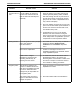
False or “ghost” The injection valve, injection
peaks. port and loop were not rinsed
out between sample injections.
Strongly retained sample
components may still be
eluting from a previous run.
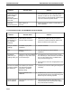
12.4 TROUBLESHOOTING THE CONDUCTIVITY FLOW CELL AND TRACE
Problem Possible Cause Solution
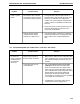
No values for There may be a loose or
buffer conductivity incorrect cable connection.
are displayed on
the Controller
status bar.
Conductivity monitor may
need calibration.
TROUBLESHOOTINGMAINTENANCE AND TROUBLESHOOTING
12-9
1. It is a good idea to allow a larger volume of
injection buffer to pass through the inject valve
and loop. For example, if the sample loop
contains 100 µl, then program a load/injection
volume of 200 µl to completely flush the valve
and loop.
2. Always clean large volume dynamic loops, such
as the Bio-Rad DynaLoop, between use to
avoid cross contamination.
3. Use stringent elution conditions or consult the
column's user manual for an appropriate wash
step to remove such components between
runs.
1. Make sure the cable from the Conductivity flow
cell is plugged into the correct connector on the
rear of the Workstation and that the pins are
not bent.
2. Use the Conductivity Flow Cell Constant
Calibration function from the Utilities drop-
down menu. Either input the constant value
which is shown onthe tag attached to the flow
cell or calibrate the flow cell using 0.5M sodium
chloride (NaCI). Note that the relationship
between the conductivity reading and salt
concentration is not linear. The curve will flatten
out at higher salt concentrations.
3. If a Maximizer is connected, make sure the
Conductivity monitor is plugged into it.