
Manual
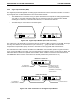
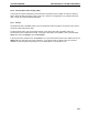

2.9.8 Model 1327 Chart Recorder
The Model 1327 chart recorder is a dual-pen chart recorder that is compatible with many detection devices.
The chart recorder includes the following features:
• Two-channel, dual-pen capability.
• Compact in size (31 x 23 x 7.6 cm).
• Voltage ranges from 1 mV to 20V.
• Twelve chart speeds for recording methods.
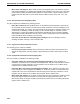
Figure 2-31. Model 1327 Chart Recorder
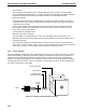
The DuoFlow Controller outputs the UV analog data signal, pen up/down, and Stop/Start commands to the
Model 1327 chart recorder via the Workstation’s UV Chart connector (cabled to the chart recorder using
System Cable 2 mini DIN to standard DIN). The Conductivity analog data signal is sent from the
Workstation’s Conductivity Chart (Cond Chart) connector to channel 2 of the chart recorder using System
Cable 4 (mini-DIN to banana plugs). The chart recorder should be set to all green settings (1V). The chart
recorder is described in detail in its separate documentation.
Note: The chart speed is set at the recorder. The BioLogic DuoFlow does not control this function.
Event marks are recorded on the chart recorder for the following:
• Fraction Collector Advance: When the fraction collector advances to the next tube.
• A manual event mark from the Run screen. Pressing the Event Mark button on the Run screen
allows you to “mark” events as they happen.
Non-Bio-Rad UV detectors: If the Model 1327 chart recorder is used in conjunction with a SIM and a third-
party detector to replace the DuoFlow UV Detector, System Cable 20 should be used to control the
recorder. Channel 1 signals should be sent directly from the third-party detector using a bare wires-to-
banana plug cable. In this case, the appropriate input voltage range must be selected on the recorder. Refer
to the documentation for your non-Bio-Rad UV detector.
2.9.9 Generic Chart Recorders
A non-Bio-Rad chart recorder may be used as an integral part of the DuoFlow system. If the DuoFlow
system’s UV detector is used, a mini-DIN to breakout cable (System Cable 7) must connect the
Workstation’s UV Chart connector to the chart recorder. Pen Up/Down and Start/Stop functions are available
providing the control polarity of the generic recorder is compatible. See the pin-out information in your chart
recorder manual.
Conductivity signals require a Bio-Rad mini-DIN to banana plug cable (System Cable 4).
Set the chart recorder’s input signal voltage to 1 V for both BioLogic DuoFlow UV detector and Conductivity
monitor signals. Chart speed is set at the recorder itself, it is not controlled by the DuoFlow system.
DESCRIPTION OF SYSTEM COMPONENTS SYSTEM OVERVIEW
2-52