
Manual

3.6 DETECTION SYSTEM CONNECTIONS
This section discusses how to connect the UV detector, the Conductivity monitor, the QuadTec detector, and
non-Bio-Rad UV detectors.
3.6.1 UV Detector and Conductivity Monitor
Two flow cells are available for use with the UV detector.
• Analytical 5 mm flow cell for high resolution protein chromatography applications and low flow rates.
It has a path length of 5 mm for maximum sensitivity and a volume of only 16 µl. It can be used with
flow rates from 0.1 to 10 ml/min.
• Preparative 2 mm flow cell for work not requiring high sensitivity, or when working with high protein
concentrations, and for flow rates greater than 10 ml/min. It has a path length of 2 mm and a volume
of 30 µl.
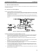
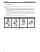
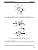
Figure 3-8. UV Detector and Conductivity Monitor
To attach the UV Detector and Conductivity Monitor to the rack:
1. Using the information provided above, confirm that the UV flow cell capacity volume is appropriate
for the flow rate. Complete discussion of the UV detector and conductivity monitor is provided in
Section 2.5, including the procedure for changing the UV flow cell.
2. Using the rod clamps, attach the UV detector to a vertical or horizontal bar close to the column
outlet.
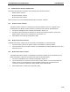
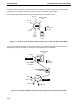
3. Connect the power cable (square connector) from the UV detector lamp into the connector marked
UV Lamp on the rear of the Workstation. Refer to Figures 3-4 and 3-5.
4. Connect the UV detector signal cable (mini-DIN connector) to the connector marked UV Optics on
the rear of the Workstation. Refer to Figures 3-4 and 3-5.
5. Connect the Conductivity monitor’s combined power and signal cable (mini-DIN connector) to the
connector marked Cond. Flow cell on the rear of the Maximizer, if available. Otherwise, connect it
to the Workstation. Refer to Figures 3-4 and 3-5.
6. The Conductivity monitor is designed to be held in the circular notch of the optics bench, but may be
placed anywhere in the fluid path.
SYSTEM SETUPSYSTEM INSTALLATION AND SETUP
3-9