
Manual

1.
Plumbing the Maximizer.
The Maximizer Tubing Kit provides colored FEP PTFE 1/8” OD, 0.062” ID, prefitted, tubing lengths.
Plumbing the Buffer Reservoirs to the Inlets on Maximizer Valves A and B
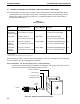
a. From the Maximizer Tubing Kit, identify the following:
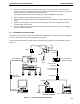
The red tubing labeled Inlet A1 connects the buffer container to the Maximizer valve port A1.
The blue tubing labeled Inlet A2 connects the buffer container to the Maximizer valve port A2.
The yellow tubing labeled Inlet B1 connects the buffer container to the Maximizer valve port B1.
The green tubing labeled Inlet B2 connects the buffer container to the Maximizer valve port B2.
For complete discussion of Maximizer tubing installation, refer to the Maximizer Tubing Kit
diagram.
b. Screw the tubing into the inlet connectors on the sides of the valves. Ensure a firm connection
but do not over-tighten.
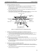
Plumbing the Maximizer Valve Outlets to the Workstation Pump Inlets
c. Connect the two preformed fittings provided between the Maximizer valve ports and the
Workstation pump inlet ports. Connect to the Workstation first.
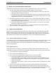
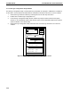
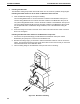
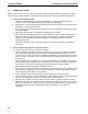
d. Because the tubing is rigid, you will need to lower the Maximizer valves in order to connect the
tubing. This requires loosening the two screws at the base of each valve so that you can tilt the
valve downward. Refer to the illustration below.
e. Insert the tubing fitting into the Maximizer outlet port and screw in the fitting.
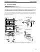
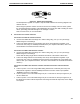
Figure 4-4. Maximizer Plumbing
B1
WATER
B2
SALT
VALVE B
1
0
SYSTEM PLUMBING SYSTEM INSTALLATION AND SETUP
4-4