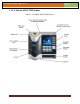
Installation Guide –April 2010 2010 CHAPTER 1 - INTRODUCTION CHAPTER OVERVIEW This chapter provides an introduction to the V-Station 4G and V-Flex 4G devices, their specifications and features, and safety guidelines that should be observed when using or handling the devices. 1.1 INTRODUCTION This manual provides step-by-step procedures for installing a L-1 Identity Solutions VStation 4G or V-Flex 4G device.
Installation Guide –April 2010 2010 NOTICE This symbol denotes a situation needing additional advice to avoid incorrect usage. 1.2 PRODUCT OVERVIEW 1.2.
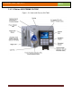
Installation Guide –April 2010 2010 1.2.
Installation Guide –April 2010 2010 1.2.
Installation Guide –April 2010 2010 1.2.
Installation Guide –April 2010 2010 1.2.
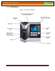
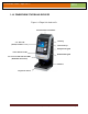
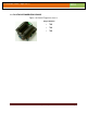
Installation Guide –April 2010 2010 1.2.6 FINGERVEIN STATION 4G DEVICES Figure 1-6 FingerVein Station 4G Internal Smart Card Reader Housing 2.
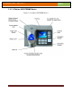
Installation Guide –April 2010 2010 1.2.7 SENSORS The V-Station 4G and V-Flex 4G devices offer three types of sensor interfaces. 1.2.7.1 UPEK TCS Figure 1-6 UPEK TCS Sensor Key Features: • Active Capacitive Fingerprint sensing • 256 x 360 Sensor Array 508 DPI • +/- 15kV Air ESD Resistance 1.2.7.2 SECUGEN OPTICAL Figure 1-7 Secugen Optical Sensor Key Features: • Optical Fingerprint sensing • 256 x 336 Sensor Array 500 DPI • +/- 15kV Air ESD Resistance 1.2.7.
Installation Guide –April 2010 2010 1.2.7.
Installation Guide –April 2010 2010 1.2.8 DEVICE DIMENSIONS 1.2.8.
Installation Guide –April 2010 2010 1.2.8.
Installation Guide –April 2010 2010 1.2.8.3 V-STATION EXTREME PIV/TWIC DEVICES 1.2.8.3.
Installation Guide –April 2010 2010 1.2.8.3.
Installation Guide –April 2010 2010 1.2.8.3.
Installation Guide –April 2010 2010 1.2.8.3.
Installation Guide –April 2010 2010 1.2.8.
Installation Guide –April 2010 2010 1.2.9 SAFETY PRECAUTIONS Below are safety precautions that should be observed when operating or installing a device. 1.2.9.1 ELECTRO-STATIC DISCHARGE L-1 Identity Solutions recommends that Administrators inform Users of these points during the enrollment process: Always use the Ridge-Lock to position a finger *before* touching the sensor. Always stand on the ESD-dissipative floor covering (if installed).
Installation Guide –April 2010 2010 Do not attempt to alter the device for any reason.Modifications will void the product guarantee. Do not attempt to disassemble the device in any way beyond what is necessary for sensor field replacement. Do not use the device for any purpose other than for what it was designed. Do not plug any equipment into the USB port other than flash memory devices. Do not allow users to place or hang objects on the device, such as coffee cups or purses.
Installation Guide –April 2010 2010 CHAPTER 2 - PLANNING THE INSTALLATION CHAPTER OVERVIEW This chapter details how to plan a successful installation, recommended steps, and explains the hardware and software components of typical setup scenarios. 2.1 PLANNING THE INSTALLATION Planning the installation is the single most important aspect of a successful installation. In general, you need to consider the access controller, the door locks, the devices, and the need for a network.
Installation Guide –April 2010 2010 V-Series 4G devices are intended for indoor use only. If you have any unresolved issues with the items on this list, contact L-1 Identity Solutions Technical Support for additional information before beginning any installation. WARNING V-Station 4G and V-Flex 4G devices should be installed by only a qualified technician. If you are not qualified to perform an installation task, call L-1 Identity Solutions Technical Support or contact a qualified installer. 2.1.
Installation Guide –April 2010 2010 2.1.2 REQUIREMENTS PC workstation with: 1 GHz Intel(r) Pentium(r) 4 processor or equivalent 1 GB RAM (2 GB recommended) CD-ROM drive One available COM port or USB port Ethernet card Display: 1024 x 768 high color (minimum) Regulated DC Power supply Door controller TCP/IP network environment RS-232 to RS-485 converter with power supply (for advanced administrative features). 2.1.2.
Installation Guide –April 2010 2010 2.1.2.2.3 MICROSOFT .NET FRAMEWORK 3.5 SP1 REQUIREMENTS Hard disk space: Up to 600 MB might be required 2.1.2.2.4 SUPPORTED OPERATING SYSTEMS SecureAdmin Server and SecureAdmin Client support these operating systems: Windows Server 2003 R2 Windows Server 2008 Windows Vista Windows XP Service Pack 2 or higher 2.1.2.2.5 SQL SERVER 2008 EXPRESS EDITION Hard disk space: 350 MB of available hard-disk space for the recommended installation.
Installation Guide –April 2010 2010 If these applications are not already installed, they will get installed during the setup process. SecureAdmin Server and SecureAdmin Client also require System Administrator access to install the application. SecureAdmin uses a self-signed certificate (x.509 certificate) with a file extension of .pfx. You have the option of installing your own certificate, which must be purchased from a recognized authority in advance.
Installation Guide –April 2010 2010 1 Micro-USB device cable 1 Micro-USB PC cable Tools 1 1/8" pin-in-hex security key 2.5 2.1.3.1.2 V-STATION 4G EXTREME DEVICES Hardware 1 V-Station Indoor or Outdoor 4G device 29 Super B-Wire Connectors, Dolphin DC-100-S 2 dielectric grease (maybe 1 is enough, need to try out) 1 Cable, User Wiegand, 4G Outdoor 8 wall mount anchor, conical, for #8 screws 1 8-32x11/32"UNC K-Lot Hex nut RoHS 1 8-32-MALE-FEMALE-HEXSTAND-1.
Installation Guide –April 2010 2010 1 FingerVein Station 4G 1 Wall mounting plate/mullion mounting plate 8 #6-32 3/4" Philips pan-head screw 8 #6 1" Philips pan-head self-tapping screws 8 #4-8 1" nylon wall anchors 29 Crimp connector, B Wire (RoHS) 2 6-32 security screw, pin-in hex, 3/8 2 0.
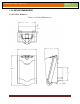
Installation Guide –April 2010 2010 2.1.4 CHOOSING THE INSTALL LOCATION V-Station 4G and V-Flex 4G devices are designed to mount on either a double-gang electrical box or on any flat surface. Consult with local professionals regarding any building and safety codes that might affect your installation. The correct mounting height is shown below.
Installation Guide –April 2010 2010 System component selection is specific to each installation, but a minimum system would consist of a finger-scan device mounted on or near an access point, an electric lock, and cabling. A more complex system might consist of devices at multiple access points (each with an electric door lock), a multi-point controller, networking, and a PC to run the access controller and SecureAdmin Server software. See the diagram below for an example (non-Ethernet) system diagram.
Installation Guide –April 2010 2010 Spec RS-485 RS-232 100BaseT Mode of Operation Differential DC Coupled Single-ended DC Coupled Multi DC Isolation No No No Maximum Distance 4000 feet 150 feet 330 feet Number of Devices on one line 31 1 Unlimited Maximum Data Rate 56 Kbps (recommended) 56 Kbps* (recommended) Autonegotiated 2.1.6.
Installation Guide –April 2010 2010 RS-485 communications. The cable connection includes a differential line (+ and -) and a GND connection. Table 2-2 Category 5 Cable Characteristics Specification Recommendation Capacitance (conductor to conductor) <20 pF/ft. Characteristic Impedance 100 - 120 ohms Nominal DC resistance <100 ohms/1000 ft. Wire gauge 24 AWG stranded Conductors/Shielding >2 pair (shielding is recommended) 2.1.6.2.
Installation Guide –April 2010 2010 NOTICE The device on the end of the network should be terminated with a 120 ohm resistor. Figure 2-3 Network Topologies Star and Daisy Chain Configurations NOTICE A Daisy configuration is recommended over a Star configuration.. 2.1.6.3 ETHERNET If your system is to be configured for use over Ethernet, the wiring will be slightly different.
Installation Guide –April 2010 2010 building walls, also impede wireless signals. Some electrical equipment, such as microwaves, large-screen TVs, cordless telephones are also known to affect wireless signals. Consider the proximity of devices to these objects. Distance from access points How far a device is from the closest access point plays a major factor in determining the stability and strength of the wireless signal.
Installation Guide –April 2010 2010 Table 2-3 V-Station 4G, V-Flex 4G and FingerVein Station 4G Power Requirements Power Requirement: 12 watts Input Voltage Range: 12-24.0 VDC Peak Current (12 VDC) 1A Peak Current (24 VDC) 500 mA Table 2-4 V-Station 4G Extreme Power Requirements Power Requirement 12 watts Input Voltage Range 12-24.
Installation Guide –April 2010 2010 CHAPTER 3 - INSTALL SOFTWARE CHAPTER OVERVIEW This chapter shows how to install, repair, modify, upgrade, and uninstall the SecureAdmin Server and Client software packages. 3.1 INSTALL SOFTWARE To install the SecureAdmin software, the user must have Administrator rights. Any software required to install SecureAdmin is detected and installed automatically during the setup process. 3.1.
Installation Guide –April 2010 2010 Figure 3-2 Prerequisites Click Install . Microsoft .NET Framework 3.5 SP1 is installed. Restart the computer when asked. The installation process continues automatically after the computer is restarted. Repeat the same process for Windows Installer 4.5.
Installation Guide –April 2010 2010 Figure 3-4 SecureAdmin Server Installation Wizard The Secure Admin Server Installation Wizard is displayed. Click Next to continue the setup process. Figure 3-5 SecureAdmin Server License Agreement The L-1 Identity Solutions License Agreement is displayed. Select the appropriate radio button to agree with the terms and then click the Next button (You must accept the terms of the licence agreement to continue the installation process).
Installation Guide –April 2010 2010 Figure 3-6 SecureAdmin Server Choose Destination Location The Choose Destination Location screen is displayed. Accept the default installation folder and click the Next button or click Browse to choose your own installation path. After you specify a destination folder, the Database Selection screen is displayed.
Installation Guide –April 2010 2010 Using the radio buttons, select the type of database application you intend to work with, or select an existing database. Click the Next button. If you selected the SQL Server 2008 Express Edition option, it will be installed locally if it is not already installed. Select SQL Server 2008 Express Edition option to install SQL Server 2008 on the local machine and Click Next.
Installation Guide –April 2010 2010 You can select existing database instance of SQL Server 2005 or SQL Server 2008 as required from the drop-down of Database server that you are installing to. Select the Database server authentication option and enter valid Login ID and password values. Accept the default database catalog or click Browse to select a different database catalog.
Installation Guide –April 2010 2010 3.1.1.1 REPAIRING AN INSTALLATION OF SECUREADMIN SERVER To repair an installation: 1. Login as Administrator and go to the Install. Double-click the Setup.exe installer file to start the installer. On the L1 Identity Solutions screen, select the Server Installation option. On the SecureAdmin Welcome screen, select the Repair option. Click Next to continue. On the Maintenance Complete screen, click the Finish button to complete the repair installation process. 3.1.1.
Installation Guide –April 2010 2010 1. When you run the setup of SecureAdmin server, it checks to see if previous version of SecureAdmin server is already installed on the machine. If yes, it prompts to upgrade SecureAdmin server. Click Yes to continue with upgrade install. Figure 3-10 Upgrade Confirmation If you have installed previous version of SecureAdmin server with SQL Server 2005, installer prompts to upgrade from SQL Server 2005 to SQL Server 2008.
Installation Guide –April 2010 2010 3.1.2 SECUREADMIN CLIENT To install the SecureAdmin client software, follow these steps: 1. Insert the CD into the optical drive. If Autoplay is enabled, the installation process will start automatically. A menu is displayed. If Autoplay is not enabled, start the installation process manually by doubleclicking the Setup.exe file located in the SecureAdmin folder on the CD. Figure 3-13 Menu Click Client Installation.
Installation Guide –April 2010 2010 Figure 3-14 InstallShield Wizard Figure 3-15 Welcome Screen Click the Next button to continue. The License Agreement screen is displayed.
Installation Guide –April 2010 2010 The L-1 Identity Solutions License Agreement is displayed. Select the appropriate radio button to agree with the terms and then click the Next button. The Choose Destination Location screen is displayed. Figure 3-17 SecureAdmin Client Choose Destination Location Accept the default installation folder and click the Next button or click Browse to choose your own installation path.
Installation Guide –April 2010 2010 Click the Next button. The InstallShield Wizard completes the installation and displays a Finished screen. Select either or both of the optional Check Create Desktop Icon and Launch Secure Admin Client check boxes. Figure 3-19 InstallShield Wizard Finished Click the Finish button. 3.1.2.1 MODIFYING AN INSTALLATION OF SECUREADMIN CLIENT To modify an installation: 1. Login as Administrator and go to the Secure Admin installer. Double-click the Setup.
Installation Guide –April 2010 2010 Double-click the Setup.exe installer file to start the installer. On the L1 Identity Solutions screen, select the Client Installation option. On the SecureAdmin Welcome screen, select the Repair option. Click Next to continue. On the Maintenance Complete screen, click the Finish button to complete the repair installation process. 3.1.2.