Veri-Series Setup Guide FCC Information to Users @ FCC 15.21 & 15.105 For Class B Unintentional Radiators: This equipment has been tested and found to comply with the limits for a Class B digital devices, pursuant to Part 15 of the FCC Rules. These limits are designed to provide reasonable protection against harmful interference in a residential installation.
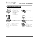
Veri-Series Setup Guide Veri-Series reader (V-Smart and V-Station differ from picture shown) Wall mounting plate / Mullion mounting plate (V-Smart and V-Station differ from picture shown ) Pigtail cable (not included for V-Station) Documentation Veri-Series Setup Guide Tools 1/8” security hex key Hardware (4) #6-32 screws (4) #6 self-tapping screws (4) #4-8 wall anchors (14) crimps (1) plastic Aux port door (2) #4-40 screws Documentation provided with your new fingerprint reader is installed onto yo
Veri-Series Setup Guide Other required equipment PC (optional for V-Station) One available COM port (or Ethernet card) Windows 98, ME, NT4, 2000, or XP 486-compatible 16 MB RAM 30 MB disk space Power supply Door controller Networking cable RS-232/RS-485 Converter P/S for converter CD with VeriAdmin software and documentation User Documentation (included on VeriAdmin CD) © Copyright 2005 Bioscrypt Inc. All rights reserved.
Veri-Series Setup Guide Introduction The Veri-Series Setup Guide provides you with general information on installing your fingerprint reader and using the reader and associated software. This document is not a substitute for the more comprehensive documentation provided with your reader and available on the CD-ROM or installed on your computer with the VeriAdmin software. Please refer to the Veri-Series Installation Guide and the Veri-Series Operations Manual for additional information.
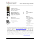
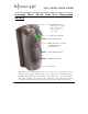
Veri-Series Setup Guide Learning More About Your New Fingerprint Reader Pass/Fail Indicator Amber – place finger Off – remove finger Green – Pass Red – Fail Conductive Plastic Power Indicator RidgeLock™ to aid in consistent finger placement Fingerprint Sensor ABS Plastic Body Aux. Port Internally, your fingerprint reader is powered by hardware and software developed by Bioscrypt. The “bioscrypt on board™” logo signifies that Bioscrypt's biometric technology has been integrated into this product.
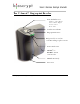
Veri-Series Setup Guide The V-Smart™ Fingerprint Reader Pass/Fail Indicator Amber – place finger Off – remove finger Green – Pass Red – Fail Conductive Plastic Fingerprint Sensor RidgeLock™ to aid in consistent finger placement Power Indicator MIFARE® or iCLASS™ smart card reader ABS Plastic Body Aux. Port © Copyright 2005 Bioscrypt Inc. All rights reserved.
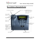
Veri-Series Setup Guide The V-Station™ Fingerprint Reader Conductive Plastic Fingerprint Sensor Pass/Fail Indicator Amber – place finger Off – remove finger Green – Pass Red – Fail LCD Backlit Display RidgeLock™ Power Indicator Illuminated Keypad Some models: MIFARE® or iCLASS™ smart card reader or HID Proximity reader Aux. Port ABS Plastic Body © Copyright 2005 Bioscrypt Inc. All rights reserved.
Veri-Series Setup Guide The Veri-Series Product Line The Veri-Series fingerprint readers are used in access control and other related fields. There are a variety of features common to the various products, but there are differences as well, as described below. For more on the operational differences between the products please see Basic Operation on page 30.
Veri-Series Setup Guide retrofit applications and for applications where a card technology other than HID is desired. V-Pass™: The V-Pass provides one-to-many fingerprint identification for small user populations (the system is optimized for user populations up to 100, but can be used for populations up to 200). The V-Pass provides fingerprint only identification – no cards or PINs are required to use the system.
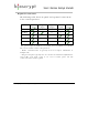
Veri-Series Setup Guide Required Connections The following table shows required and optional connections to the various products. Product Power Input V-Prox Wiegand Wiegand Input Output *** V-Flex *** V-Pass *** V-Smart V-Station * * Serial Earth Comm. Ground ** ** *** *** ** The power input on V-Smart is 9-12 VDC and 12.5-24VDC on V-Station instead of 9-24 VDC on the other products. * RS-485 communication is typically used for template distribution to multiple units.
Veri-Series Setup Guide Preparing Wiring 1. Wiring connections to be made: Wiegand – should be 18-22 AWG (10-7 MWG) wire, between 3 and 6 conductors depending on which signals will be carried, shielded cable is recommended, and typically the conductors are made of stranded wire. Minimum connections: Data0, Data1, Wiegand Ground RS-485 – use category 5 shielded cable. Ethernet – use category 5 shielded cable Power – should be 18 – 22 AWG (10 – 7 MWG) wire, 2 conductors.
Veri-Series Setup Guide 2.
Veri-Series Setup Guide 3. Weidmuller Connections (V-Station only): Group Label Signal Description RS-485 RS-232 Power/Ground Wiegand TTL (IN) TTL (OUT) TX(+) TX(-) RX(+) RX(-) GND GND TX RX +(POS) -(NEG) EGND IN 0 IN 1 OUT 0 OUT 1 LED IN LED OUT GND IN 0 IN 1 OUT 0 H OUT 1 L GND Transmit + Transmit Receive + Receive RS-485 Ground RS-232 Ground Transmit Receive 12.5 - 24 VDC + 12.
Veri-Series Setup Guide Power Supply 2 Unit Door Controller 3 Unit Unit Unit Cat5 Twisted Pair Data0 Data1 Wiegand Gnd. RS-232 /RS-485 Converter Computer Use one pair (e.g. blue/white and white/blue) for RS-485 connections. Connect readers identically at each reader (e.g. blue/white on Cat5 to RS-485 (-) on pigtail/Weidmuller Connector and white/blue on Cat5 to RS-485 (+) on pigtail/Weidmuller Connector). 5. [RS-485 network only]: At converter, jumper TD(A) with RD(A) and TD(B) with RD(B).
Veri-Series Setup Guide 7. [RS-485 network only]: Set up network using 9600 baud rate. Only increase this data rate after the system is operating properly at 9600. 8. [Ethernet network only]: Typically a star network topology is used with a network switch or hub, but a bus topology may be used. Be sure to connect all devices using straight-thru (as apposed to cross-over) cables. The exception to this is when connecting a single device directly to the computer Ethernet adaptor. 9.
Veri-Series Setup Guide Configuring Readers See Page 11 for Color Codes +12 VDC Pigtail OR Weidmuller Ground Wiegand Out Data0 Wiegand Out Data1 Wiegand Ground To Computer Power Supply Door Controller Data 0 Data 1 Common Earth Ground 1. Set up a configuration station a. Wire the unit for power: • V-Prox/V-Flex/V-Pass: Connect the RED pigtail wire to 9-24V DC power and the BLACK wire to power ground. • V-Smart: Connect the RED pigtail wire to 9-12V DC power and the BLACK wire to power ground.
Veri-Series Setup Guide 3. Configure the device using the VeriAdmin software provided a. If running VeriAdmin for the first time, you will be directed to the Network Setup dialog. This dialog is also reached by clicking on this icon: . Select the serial (COM) port(s) you intend to use or Ethernet and click OK. It is recommended that you check “Auto”. © Copyright 2005 Bioscrypt Inc. All rights reserved.
Veri-Series Setup Guide b. This will bring you to the Network Configuration Manager dialog. First click on the Comm port or Ethernet within the network tree which you have connected the unit to (the or icon). Then click on the “Add Unit” button (lower left). © Copyright 2005 Bioscrypt Inc. All rights reserved.
Veri-Series Setup Guide c. VeriAdmin should establish communication with the unit. The Unit Status field should indicate ONLINE, you may hear the unit beep, and other fields on the right side should populate. If you are connecting via Ethernet, you must first assign the unit an IP address from the unit’s keypad and then type in the address under Ethernet Settings and click the Refresh button. d. If VeriAdmin shows NOT RESPONDING, check the connections and then press the Refresh button to try again. e.
Veri-Series Setup Guide g. Change desired parameters. Typical changes are: i. Communication Tab: Network ID (default is 0, but each unit must have a unique ID number such as 1, 2, 3, 4, etc.) ii. Wiegand Tab: Wiegand parameters NOTE: We do not recommend changing the Aux. port Baud rate at this time. 4. Repeat steps 2-4 (skipping 3a) for the next reader until all readers are configured. © Copyright 2005 Bioscrypt Inc. All rights reserved.
Veri-Series Setup Guide 5. If placing units on a RS-485 network, you will also need to set up the computer for RS-485 communications. a. Connect the RS-232/RS-485 converter to the PC’s COM port (must support Send Data – a means of automatically sensing data sent from the RS-232 port – we suggest the B&B Electronics, www.bb-elec.com, model 485TBLED or equivalent). b. Run category 5 rated cable from the converter to the first reader in the daisy chain. 6. V-Smart considerations a.
Veri-Series Setup Guide 7. V-Station considerations a. The V-Station does not require configuration via a PC. Nearly all configuration options can be set using the menus on the unit. However, it may be more convenient to administer the device from the PC due to the limited size of the LCD screen. b. To distribute templates to other V-Stations, you will need to place all V-Stations on a network and administer them via the PC.
Veri-Series Setup Guide Mounting Readers On The Wall 1. The readers come disassembled, however, if your reader has previously been assembled then disassemble the reader body and smart card module (for V-Smart only) from the wall plate. a. On V-Smart remove security screw securing smart card module b. For products other than V-Station, remove security screw securing the Aux. port cover, and remove the Aux. port cover by twisting (see graphics on page 25). c.
Veri-Series Setup Guide c. Provide clearance above and below for access d. The access hole in the wall for wiring should be less than 1 ½ inches wide so that wall plate will cover it. It should be less than 1 ½ inches tall if mounting into dry wall so that there is enough material to hold the anchor. The recommended size is 1 inch wide by 1 1/8 inches tall to match the opening in the wall plate. e.
Veri-Series Setup Guide 6. Feed main pigtail DB15 connector (not applicable to VStation) through wall plate from the back and proceed to mount wall plate: a. Optionally mount to a gang box using #6-32 screws provided. b. Optionally mount on wall. i. Use 4 outer mounting points (6 for V-Station). ii. Up to #6 screws can be accepted (screws and drywall anchors are provided). c. Use template provided to mark holes. 7.
Veri-Series Setup Guide 3) with tab in the reader body groove, rotate the cover clockwise until the right tab snaps into place at the right rear corner Step 1 Step 2 Step 3 4) Finally, fold the cover up and secure it using the supplied security screw and special Allen wrench. The following pages show the dimensions of the wall mounting plates for the smaller Veri-Series readers (V-Prox, V-Flex, V-Pass), the V-Smart, and the V-Station.
Veri-Series Setup Guide 2 ¾” (70 mm) 1 1/8” (28 5 5/16” (135 mm) 5/32” ø 1 ¼” (32 mm) 1 1/8” (28 mm) 11/16” (17 mm) 3 ¼” (82 mm) 1” (25 2 5/8” (67 mm) Mounting Template for V-Prox / V-Flex / V-Pass (not to scale) © Copyright 2005 Bioscrypt Inc. All rights reserved.
Veri-Series Setup Guide Mounting Template for V-Smart (MIFARE and iCLASS) (not to scale) © Copyright 2005 Bioscrypt Inc. All rights reserved.
Veri-Series Setup Guide Mounting template for V-Station (all models) (not to scale) © Copyright 2005 Bioscrypt Inc. All rights reserved.
Veri-Series Setup Guide Basic Operation 1. Use VeriAdmin software to enroll a new fingerprint: Enrollment is the process of generating data that the reader will store and use to later verify your identity. a. Make sure that the correct unit is identified on the main toolbar dropdown. b. Go to the Template Manager screen. c. Click on Quick Enroll. d. Enter an ID number.
Veri-Series Setup Guide score of 3 stars for quality and 2 stars for content. If enrollment scores for Content and Quality are acceptable, then click on Accept. g. Fill in desired information and decide where the template will be stored (either on PC, the unit used to enroll, or a smart card). Click on the appropriate “Save” button. © Copyright 2005 Bioscrypt Inc. All rights reserved.
Veri-Series Setup Guide h. If templates are saved to the PC or the unit and are to be distributed to other readers, then this can be done using the Template Manager functions. In the case of VSmart, the template is stored on the smart card and does not need to be distributed. 2. Using the keypad to enroll a new fingerprint (V-Station only): a. From the idle screen (showing ”Bioscrypt” with the date and time), press 0-0-0 (three zeroes) and . You will be warned about no admin ID. b.
Veri-Series Setup Guide h. Choose the security level, 0 – 6 (0 = none, 1 = very high, 2 = high, … 5 = very low, 6 = Password Only). You may i. press for the default (3). Choose the admin level 0 – 2 (0 = user, 1 = enroller, 2 = full admin). You may press for the default (user). j. Enter a password for the template, if desired, or for none. k. If the unit is a V-Station MIFARE or V-Station iCLASS, the next menu will ask if you would like to save the template to the unit (1) or to a smart card (2).
Veri-Series Setup Guide c. When the light turns off, remove the finger and the door lock will release if the verification was successful (reader will indicate green for success or red for failure). 4. Cleaning and care of the sensor The fingerprint sensor is a solid-state device designed to provide years of trouble-free service. Although there is little to do in terms of maintenance, a few basics in caring for the sensor will help to ensure a high level of performance over the life of the sensor.
Veri-Series Setup Guide Disclaimer The instructions in this document have been carefully checked for accuracy and are presumed to be reliable. Bioscrypt, Inc. and its writers assume no responsibility for inaccuracies and reserve the right to modify and revise this document without notice. It is always our goal at Bioscrypt, Inc. to supply accurate and reliable documentation. If you discover a discrepancy in this document, please e-mail your comments to support@bioscrypt.
Veri-Series Setup Guide Bioscrypt One Year Limited Warranty Policy Bioscrypt warrants to the original consumer purchaser (“Customer”) that new Bioscrypt products will be free from defects in material and workmanship for one year from the date the product was shipped from Bioscrypt. For replacement products the warranty on the replacement unit is the remainder of the warranty on the original product or ninety (90) days, whichever is longer.
Veri-Series Setup Guide defaced, altered, or removed or if the product has been modified. Repair and replacement parts will be furnished on an exchange basis and may be either reconditioned or new. All replaced parts or products become the property of Bioscrypt. This warranty may also be voided for failure to comply with Bioscrypt’s return policy.
Veri-Series Setup Guide range. Product failures resulting from exposure to these conditions are not covered under the product warranty. For outdoor installations, Bioscrypt does offer an enclosure to protect the device from exposure to moisture, dust, other contaminants and temperatures outside stated operating range. To maintain the Bioscrypt warranty, the Veri-Series unit must be installed in a Bioscrypt certified outdoor enclosure.
Veri-Series Setup Guide Bioscrypt Return Policy and Procedures Bioscrypt must be notified within thirty days of the date that a defect is discovered. Bioscrypt will then issue a Return Material Authorization (RMA) number which the Customer must include with all correspondence and display on the outside of the shipping container when returning the product. Any products returned later than 30 days after issuance of an RMA may be subject to review as to whether the authorization to return is still warranted.
Veri-Series Setup Guide Carefully read the following regarding billable repairs: By shipping product to Bioscrypt using the RMA provided by the Technical Support Department, you are agreeing to the following terms: For all non-warranty repairs or billable repairs, the customer will be responsible for charges associated with parts, labor and shipping/freight to and from the Bioscrypt repair facility.
Veri-Series Setup Guide 30 Day Return for Credit Bioscrypt is a leading biometric company, specializing in fingerprint and verification systems. We are confident that customers will be pleased with Bioscrypt products.
Veri-Series Setup Guide Notices The Veri-Series line of products has been tested for compliance with all applicable international standards. The resulting approvals are listed below, and are additionally printed on the labeling located on the rear panel of the product. The power supply offered by Bioscrypt is CE and CSA approved and UL listed.
Veri-Series Setup Guide are designed to provide reasonable protection against harmful interference in a residential installation. This equipment generates, uses, and can radiate radio frequency energy and, if not installed and used in accordance with the instruction manual, may cause harmful interference to radio communications. However, there is no guarantee that interference will not occur in a particular installation.
Veri-Series Setup Guide Technical Support Contact Information: Telephone: 866.304.7180 (toll free) 818.304.7180 Fax: 818.304.7187 Email: Web: support@bioscrypt.com http://www.bioscrypt.com Hours: 5:30A – 5:00P PST (Monday – Friday) Address Bioscrypt Inc. Technical Support Department 5805 Sepulveda Blvd., Suite 750 Van Nuys, CA 91411 © Copyright 2005 Bioscrypt Inc. All rights reserved.
Veri-Series Setup Guide For your records Model: Serial Numbers: Installer/Reseller: Installation Date: Notes: Corporate & Canadian Office 505 Cochrane Dr, Markham, ON, Canada L3R 8E3 T 905 940 7750 F 905 940 7642 www.bioscrypt.com U.S. Office 5805 Sepulveda Blvd., Suite 750 Van Nuys, CA 91411 T 818 304 7150 F 818 461-0843 U.K. Office 35 Jackson Court, Hazlemere High Wycombe, Buckinghamshire England HP15 7TZ T +44 (0) 1494 814 404 F +44 (0) 1494 815 513 © Copyright 2005 Bioscrypt Inc.