
User's Manual


POWER DISTRIBUTION & READER HOOKUP
Part # 430-00186-00 ©Copyright 2007, Bioscrypt Inc.
PIV-Station Installation Guide All rights reserved.
27
12.3 Wiegand Connections
Wiegand output lines should be connected to a Wiegand compatible controller. When connecting Wiegand
output to a controller, you must make sure that the connection is using Data0, Data1, and a common Ground
reference. See Table 5 above for the wiring of the Wiegand and Figure 14 for the layout on the back of the PIV-
Station.
12.4 ESD Shield Earth Ground Requirement
The finger mask (conductive plastic surrounding the finger-scan sensor) is sometimes referred to as an ESD
Shield. The cable (14-18 AWG) that should be used for the ESD Shield is dependent on length. EGND on the
unit should be connected in a direct (homerun) configuration to a solid Earth Ground such as a cold water
copper pipe or a building ground. See Section 2 for details. Do not connect the ESD Shield to Power
Ground! The solid Earth Ground connection chosen should measure less than 4 ohm resistance when
measured against a known Earth Ground.
12.5 RS-485
RS-232, RS-485, and USB can be used for communication with a PC running PIV-Station compatible software
(such as our VeriAdmin software). RS-232 and USB communication is only used for a single reader at a time.
If readers are networked, RS-485 connection protocol must be used. For a PC that is administering a RS-485
network, a RS-232 to RS-485 converter is required. RS-485 connections among various readers should be
made by connecting the (+) and (-) lines of the differential RS-485 in a daisy chain manner. For instance, from
V-Prox to V-Prox, the (+) line from one V-Prox is connected to the (+) line of the next V-Prox and so on; likewise
for the (-) lines. Additionally, connect the grounds from each V-Prox reader back to the signal ground
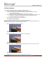
connection for the PC. Figure 14 below shows the wiring of an RS-232 to RS-485 converter (Shown with
optional VeriSeries readers for reference.).
Figure 14: Wiring Diagram for RS-232 to RS-485 Converter
12.6 Network Operation Issues:
• Use Category 5 cabling for a RS-485 network.
• Choose one twisted pair of conductors to use for RS-485 differential connection, other conductors
should be used for Signal Ground (RS-485 GND on Weidmuller connection).
• RS-232/RS-485 Converter must support sense data to switch from send to receive mode.
o Check each reader/cabling for ground fault before connecting to RS-485 network.
o Each reader should have its ESD Shield Ground (EGND) connected to Earth Ground.
o Once all readers are configured and connected to the RS-485 network, the baud rate can be
increased to highest supported rate (some experimentation required).
• Reader will return a busy signal (error –104) if communication cannot be processed due to current
processing – usually enroll or verify.