945GC-M4 Setup Manual FCC Information and Copyright This equipment has been tested and found to comply with the limits of a Class B digital device, pursuant to Part 15 of the FCC Rules. These limits are designed to provide reasonable protection against harmful interference in a residential installation. This equipment generates, uses, and can radiate radio frequency energy and, if not installed and used in accordance with the instructions, may cause harmful interference to radio communications.
Table of Contents Chapter 1: Introduction ............................................................ 1 1.1 Before You Start ................................................................................ 1 1.2 Package Checklist ............................................................................. 1 1.3 Motherboard Features...................................................................... 2 1.4 1.5 Rear Panel Connectors .....................................................................
945GC-M4 CHAPTER 1: INTRODUCTION 1.1 BEFORE YOU START Thank you for choosing our product. Before you start installing the motherboard, please make sure you follow the instructions below: Prepare a dry and stable working environment with sufficient lighting. Always disconnect the computer from power outlet before operation.
Motherboard Manual 1.3 MOTHERBOARD FEATURES SPEC CPU FSB Chipset Socket 478 Supports Hyper-Threading / Execute Disable Bit / Intel Pentium4 /Celeron D / Celeron 3xx Enhanced Intel SpeedStep® / Intel Architecture-64 / processors (Maximum Watt: 95W) Extended Memory 64 Technology Support 800 / 533 MHz Intel 945GC Intel ICH7 ITE 8712F Super I/O Provides the most commonly used legacy Environment Control initiatives, Super I/O functionality.
945GC-M4 SPEC Front Panel Connector x1 Supports front panel facilities Front Audio Connector x1 Supports front panel audio function S/PDIF out Connector x1 Supports digital audio out function CPU Fan Header x1 CPU Fan power supply System Fan Header x1 System Fan Power supply Clear CMOS Header x1 Restore CMOS data to factory default USB Connector x2 Each connector supports 2 front panel USB ports Power Connector (24pin) x1 Connects to Power supply Power Connector (4pin) x1 Connects
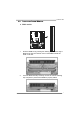
Motherboard Manual 1.5 MOTHERBOARD LAYOUT KBMS1 CPU_FAN1 S oc ket 47 8 ATXPWR1 D DR2_B1 VG A1 D DR2_A1 ATXPWR2 JUSBV1 USB2 RJ45USB1 ID E1 Intel 945GC BIOS AUDIO1 F_AUDIO1 PEX16_1 LAN BAT1 PCI1 Super I/O Intel ICH7 PCI2 JPRINT1 JCOM1 JSPDIFOUT1 SATA1 F_USB3 F_USB4 FDD1 SYS_FAN1 JCMOS1 Note: ■ represents the 1st pin.
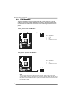
945GC-M4 CHAPTER 2: HARDWARE INSTALLATION 2.1 INSTALLING CENTRAL PROCESSING UNIT (CPU) Step 1: Pull the lever sideways away from the socket and then raise the lever up to a 90-degree angle. Step 2: Look for the white dot/cut edge. The white dot/cut edge should point wards the lever pivot. The CPU will fit only in the correct orientation. Step 3: Hold the CPU down firmly, and then close the lever to complete the installation. Step 4: Put the CPU Fan on the CPU and buckle it.
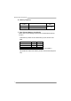
Motherboard Manual 2.2 FAN HEADERS These fan headers support cooling-fans built in the computer. The fan cable and connector may be different according to the fan manufacturer. Connect the fan cable to the connector while matching the black wire to pin#1.
45GC-M4 2.3 INSTALLING SYSTEM MEMORY DD R2_B1 DD R2_A1 A. DDR2 module 1. Unlock a DIMM slot by pressing the retaining clips outward. Align a DIMM on the slot such that the notch on the DIMM matches the break on the Slot. 2. Insert the DIMM vertically and firmly into the slot until the retaining chip snap back in place and the DIMM is properly seated.
Motherboard Manual B. Memory Capacity DIMM Socket Location DDR2 Module DDR2_A1 256MB/512MB/1GB/2GB DDR2_B1 256MB/512MB/1GB/2GB Total Memory Size Max is 4GB. C. Dual Channel Memory Installation Please refer to the following requirements to activate Dual Channel function: Install memory module of the same density in pairs, shown in the table. Dual Channel Status DDR2_A1 DDR2_B1 Disabled O X Disabled X O Enabled O O (O means memory installed, X means memory not installed.
945GC-M4 2.4 CONNECTORS AND SLOTS FDD1: Floppy Disk Connector The motherboard provides a standard floppy disk connector that supports 360K, 720K, 1.2M, 1.44M and 2.88M floppy disk types. This connector supports the provided floppy drive ribbon cables. 2 34 1 33 IDE1: Hard Disk Connector The motherboard has a 32-bit Enhanced PCI IDE Controller that provides PIO Mode 0~4, Bus Master, and Ultra DMA 33/66/100 functionality.
Motherboard Manual ATXPWR1: ATX Power Source Connector This connector allows user to connect 24-pin power connector on the ATX power supply. Pin 13 14 15 16 17 18 19 20 21 22 23 24 Assignment +3.3V -12V Ground PS_ON Ground Ground Ground NC +5V +5V +5V Ground Pin 1 2 3 4 5 6 7 8 9 10 11 12 12 24 1 13 Assignment +3.3V +3.3V Ground +5V Ground +5V Ground PW_OK Standby Voltage+5V +12V +12V +3.3V ATXPWR2: ATX Power Source Connector By connecting this connector, it will provide +12V to CPU power circuit.
945GC-M4 PEX16_1: PCI-Express x16 Slot - PCI-Express 1.0a compliant. Maximum theoretical realized bandwidth of 4GB/s simultaneously per direction, for an aggregate of 8GB/s totally. PCI-Express supports a raw bit-rate of 2.5Gb/s on the data pins. 2X bandwidth over the traditional PCI architecture. PEX16_1 PCI1/PCI2: Peripheral Component Interconnect Slots This motherboard is equipped with 2 standard PCI slots.
Motherboard Manual CHAPTER 3: HEADERS & JUMPERS SETUP 3.1 HOW TO SETUP JUMPERS The illustration shows how to set up jumpers. When the jumper cap is placed on pins, the jumper is “close”, if not, that means the jumper is “open”. Pin opened 3.2 Pin closed Pin1-2 closed DETAIL SETTINGS PANEL1: Front Panel Header This 16-pin connector includes Power-on, Reset, HDD LED, Power LED, and speaker connection. It allows user to connect the PC case’s front panel switch functions.
945GC-M4 F_USB3/F_USB4: Headers for USB 2.0 Ports at Front Panel This motherboard provides 2 USB 2.0 headers, which allows user to connect additional USB cable on the PC front panel, and also can be connected with internal USB devices, like USB card reader. JU SB3 JUSB4 2 10 1 9 Pin 1 2 3 4 5 6 7 8 9 10 Assignment +5V (fused) +5V (fused) USBUSBUSB+ USB+ Ground Ground Key NC JUSBV1/JUSBV2: Power Source Headers for USB Ports Pin 1-2 Close: JUSBV1: +5V for USB ports at USB2/RJ45USB1.
Motherboard Manual F_AUDIO1: Front Panel Audio Header This header allows user to connect the front audio output cable with the PC front panel. This header allows only HD audio front panel connector; AC’97 connector is not acceptable. 10 9 2 1 Pin 1 2 3 4 5 6 7 8 9 10 Assignment Mic Left in Ground Mic Right in GPIO Right line in Jack Sense Front Sense Key Left line in Jack Sense JSPDIFOUT1: Digital Audio-out Connector This connector allows user to connect the PCI bracket SPDIF output header.
945GC-M4 JCMOS1: Clear CMOS Header By placing the jumper on pin2-3, it allows user to restore the BIOS safe setting and the CMOS data, please carefully follow the procedures to avoid damaging the motherboard. 1 3 Pin 1-2 Close: Normal Operation (Default). 1 3 1 Pin 2-3 Close: Clear CMOS data. 3 ※ Clear CMOS Procedures: 1. 2. 3. 4. 5. Remove AC power line. Set the jumper to “Pin 2-3 close”. Wait for five seconds. Set the jumper to “Pin 1-2 close”. Power on the AC. 6.
Motherboard Manual JCOM1: Serial Port Connector The motherboard has a Serial Port Connector for connecting RS-232 Port. 2 10 1 9 Pin 1 2 3 4 5 6 7 8 9 10 Assignment Carrier detect Received data Transmitted data Data terminal ready Signal ground Data set ready Request to send Clear to send Ring indicator Key JPRINT1: Printer Port Connector This header allows you to connector printer on the PC.
945GC-M4 CHAPTER 4: USEFUL HELP 4.1 DRIVER INSTALLATION NOTE After you installed your operating system, please insert the Fully Setup Driver CD into your optical drive and install the driver for better system performance. You will see the following window after you insert the CD The setup guide will auto detect your motherboard and operating system. Note: If this window didn’t show up after you insert the Driver CD, please use file browser to locate and execute the file SETUP.
Motherboard Manual 4.2 SOFTWARE Installing Software 1. Insert the Setup CD to the optical drive. The drivers installation program would appear if the Autorun function has been enabled. 2. Select Software Installation, and then click on the respective software title. 3. Follow the on-screen instructions to complete the installation. Launching Software After the installation process, you will see the software icon “eHOT Line” / “BIOS Update” appears on the desktop.
945GC-M4 After filling up this information, click “Send” to send the mail out. A warning dialog would appear asking for your confirmation; click “Send” to confirm or “Do Not Send” to cancel. If you want to save this information to a .txt file, click “Save As…” and then you will see a saving dialog appears asking you to enter file name. Enter the file name and then click “Save”. Your system information will be saved to a .txt file. Open the saved .
Motherboard Manual BIOS Update BIOS Update is a convenient utility which allows you to update your motherboard BIOS under Windows system. AWARD BIOS Show current BIOS information AMI BIOS Clear CMOS function (Only for AWARD BIOS) Save current BIOS to a .bin file Update BIOS with a BIOS file Once click on this button, the saving dialog will show. Choose the position to save file and enter file name.
945GC-M4 Before doing this, please download the proper BIOS file from the website. For AWARD BIOS, update BIOS procedure should be run with Clear CMOS function, so please check on Clear CMOS first. Then click Update BIOS button, a dialog will show for asking you backup current BIOS. Click Yes for BIOS backup and refer to the Backup BIOS procedure; or click No to skip this procedure.
Motherboard Manual 4.3 EXTRA INFORMATION CPU Overheated If the system shutdown automatically after power on system for seconds, that means the CPU protection function has been activated. When the CPU is over heated, the motherboard will shutdown automatically to avoid a damage of the CPU, and the system may not power on again. In this case, please double check: 1. The CPU cooler surface is placed evenly with the CPU surface. 2. CPU fan is rotated normally. 3.
945GC-M4 BIO-Flasher BIO-Flasher is a BIOS flashing utility providing you an easy and simple way to update your BIOS via USB pen drive or floppy disk. The BIO-Flasher is built in the BIOS chip. To enter the utility, press during the Power-On Self Tests (POST) procedure while booting up. Updating BIOS with BIO-Flasher 1. Go to the website to download the latest BIOS file for the motherboard. 2. Then, save the BIOS file into a USB pen drive or a floppy disk. 3.
Motherboard Manual 4.4 AMI BIOS BEEP CODE Boot Block Beep Codes Number of Beeps 1 2 3 4 5 7 10 11 12 13 Description No media present. (Insert diskette in floppy drive A:) “AMIBOOT.ROM” file not found in root directory of diskette in A: Insert next diskette if multiple diskettes are used for recovery Flash Programming successful File read error No Flash EPROM detected Flash Erase error Flash Program error “AMIBOOT.
945GC-M4 4.5 TROUBLESHOOTING Probable 1. There is no power in the system. Power LED does not shine; the fan of the power supply does not work 2. Indicator light on keyboard does not shine. System is inoperative. Keyboard lights are on, power indicator lights are lit, and hard drives are running. System does not boot from a hard disk drive, but can be booted from optical drive. Solution 1. 2. 3. Make sure power cable is securely plugged in. Replace cable. Contact technical support.
Motherboard Manual APPENDIX: SPEC IN OTHER LANGUAGES GERMAN Spezifikationen CPU FSB Sockel 478 Unterstützt Hyper-Threading / Execute Disable Bit / Intel Pentium4 /Celeron D / Celeron 3xx Enhanced Intel SpeedStep® / Intel Architecture-64 / Prozessoren (Maximales Watt: 95W) Extended Memory 64 Technology 800 / 533 MHz Intel 945GC Chipsatz Intel ICH7 ITE 8712F Bietet die häufig verwendeten alten Super Umgebungskontrolle, Super E/A E/A-Funktionen.
945GC-M4 Spezifikationen Diskettenlaufwerkanschluss x1 Jeder Anschluss unterstützt 2 Diskettenlaufwerke Druckeranschluss Anschluss x1 Jeder Anschluss unterstützt 1 Druckeranschluss Serieller Anschluss x1 IDE-Anschluss x1 Jeder Anschluss unterstützt 2 IDE-Laufwerke SATA-Anschluss x4 Jeder Anschluss unterstützt 1 SATA-Laufwerk Fronttafelanschluss x1 Unterstützt die Fronttafelfunktionen Front-Audioanschluss x1 Unterstützt die Fronttafel-Audioanschlussfunktion S/PDIF- Ausgangsanschluss x1
Motherboard Manual FRENCH SPEC Prend en charge les technologies Hyper-Threading / Socket 478 UC d'exécution de bit de désactivation / Intel SpeedStep® Processeurs Intel Pentium4 /Celeron D / optimisée/ d'architecture Intel 64 / de mémoire Celeron 3xx (Watt maximum : 95W) étendue 64 Bus frontal 800 / 533 MHz Intel 945GC Chipset Intel ICH7 ITE 8712F Super E/S Fournit la fonctionnalité de Super E/S Initiatives de contrôle environnementales, patrimoniales la plus utilisée.
945GC-M4 SPEC Connecteur de disquette x1 Connecteur de Port d'imprimante x1 Port série x1 Connecteur IDE x1 Connecteur SATA x4 Connecteur du panneau avant Chaque connector prend en charge 2 lecteurs de disquettes Chaque connector prend en charge 1 Port d'imprimante Chaque connecteur prend en charge 2 périphériques IDE Chaque connecteur prend en charge 1 périphérique SATA x1 Prend en charge les équipements du panneau avant Connecteur Connecteur Audio du panneau avant x1 Prend en charge la fon
Motherboard Manual ITALIAN SPECIFICA Socket 478 CPU Supporto di Hyper-Threading / Execute Disable Processori Intel Pentium4 /Celeron D / Bit / Enhanced Intel SpeedStep® / Architettura Celeron 3xx (Watt massimo: 95W) FSB Intel 64 / Tecnologia Extended Memory 64 800 / 533 MHz Intel 945GC Chipset Intel ICH7 ITE 8712F Fornisce le funzionalità legacy Super Funzioni di controllo dell’ambiente: Super I/O Monitoraggio hardware I/O usate più comunemente.
945GC-M4 SPECIFICA Connettori su scheda Connettore floppy x1 Ciascun connettore supporta 2 unità Floppy Connettore Porta stampante x1 Ciascun connettore supporta 1 Porta stampante Porta seriale x1 Connettore IDE x1 Ciascun connettore supporta 2 unità IDE Connettore SATA x4 Ciascun connettore supporta 1 unità SATA Connettore pannello frontale x1 Supporta i servizi del pannello frontale Connettore audio frontale x1 Supporta la funzione audio pannello frontale Connettore output SPDIF x1
Motherboard Manual SPANISH Especificación Conector 478 CPU Admite Hyper-Threading / Bit de deshabilitación de Procesadores Intel Pentium4 /Celeron D / ejecución / Intel SpeedStep® Mejorado / Intel Celeron 3xx (Vatio máximo: 95W) FSB Architecture-64 / Tecnología Extended Memory 64 800 / 533 MHz Conjunto de Intel 945GC chips Intel ICH7 ITE 8712F Le ofrece las funcionalidades heredadas de Iniciativas de control de entorno, Súper E/S Monitor hardware uso más común Súper E/S.
945GC-M4 Especificación Conector disco flexible X1 Cada conector soporta 2 unidades de disco flexible Conector Puerto de impresora X1 Cada conector soporta 1 Puerto de impresora Puerto serie X1 Conector IDE X1 Cada conector soporta 2 dispositivos IDE Conector SATA X4 Cada conector soporta 1 dispositivos SATA Conector de panel frontal X1 Soporta instalaciones en el panel frontal Conector de sonido frontal X1 Soporta funciones de sonido en el panel frontal Conectores Conector de salida S/P
Motherboard Manual PORTUGUESE ESPECIFICAÇÕES Socket 478 CPU Suporta as tecnologias Hyper-Threading / Execute Processadores Intel Pentium4 /Celeron D / Disable Bit / Enhanced Intel SpeedStep® / Intel Celeron 3xx (Watt máximo: 95W) FSB Chipset Arquitecture -64 / Extended Memory 64 800 / 533 MHz Intel 945GC Intel ICH7 ITE 8712F Especificaçã o Super I/O Proporciona as funcionalidades mais utilizadas em termos da especificação Super I/O.
945GC-M4 ESPECIFICAÇÕES Conector da unidade de disquetes x1 Cada conector suporta 2 unidades de disquetes Conector da para impressora x1 Cada conector suporta 1 Porta para impressora Porta série x1 Conector IDE x1 Cada conector suporta 2 dispositivos IDE Conector SATA x4 Cada conector suporta 1 dispositivo SATA Conector do painel frontal x1 Para suporte de várias funções no painel frontal Conector de áudio frontal x1 Suporta a função de áudio no painel frontal Conector de saída S/PDIF x
Motherboard Manual POLISH SPEC Procesor FSB Socket 478 Obsługa Hyper-Threading / Execute Disable Bit / Intel Pentium4 /Celeron D / Celeron 3xx Enhanced Intel SpeedStep® / Intel Architecture-64 / Procesory (Maksymalny Watt: 95W) Extended Memory 64 Technology 800 / 533 MHz Intel 945GC Chipset Intel ICH7 Gniazda DDR2 DIMM x 2 Moduł pamięci DDR2 z trybem podwójnego kanału Pamięć Każde gniazdo DIMM obsługuje moduły główna 256MB / 512MB / 1GB / 2GB Obsługa DDR2 400/533/667 Brak obsługi Registered D
945GC-M4 SPEC Złącza wbudowane Złącze napędu dyskietek x1 Każde złącze obsługuje 2 napędy dyskietek Złącze Port drukarki x1 Każde złącze obsługuje 1 Port drukarki Port szeregowy x1 Złącze IDE x1 Każde złącze obsługuje 2 urządzenia IDE Złącze SATA x4 Każde złącze obsługuje 1 urządzenie SATA Złącze panela przedniego x1 Obsługa elementów panela przedniego Przednie złącze audio x1 Obsługa funkcji audio na panelu przednim Złącze wyjścia S/PDIF x1 Obsługa funkcji cyfrowego wyjścia audio Z
Motherboard Manual RUSSIAN СПЕЦ CPU (центральн ый Гнездо 478 Поддержка технологий Hyper-Threading / Execute Процессоры Intel Pentium4 /Celeron D / Disable Bit / Enhanced Intel SpeedStep® / Intel процессор) Celeron 3xx (Максимальный ватт: 95W) Architecture-64 / Extended Memory 64 Technology FSB 800 / 533 МГц Набор Intel 945GC микросхем Intel ICH7 Слоты DDR2 DIMM x 2 Модуль памяти с двухканальным режимом DDR2 Основная Каждый модуль DIMM поддерживает Поддержка DDR2 400/533/667 память 256 МБ / 51
945GC-M4 СПЕЦ Разъём НГМД x1 Разъём Порт подключения Каждый разъём поддерживает 1 Порт подключения принтера x1 Последовательный порт x1 Разъём IDE x1 принтера Каждый разъём поддерживает 2 встроенных интерфейса накопителей Разъём SATA x4 Каждый разъём поддерживает 1 устройство SATA Разъём на лицевой панели x1 Поддержка устройств на лицевой панели Входной звуковой разъём x1 Поддержка звуковых функций на лицевой панели x1 Поддержка вывода цифровой звуковой функции Встроенны Разъём вывода
Motherboard Manual ARABIC اﻟﻤﻮاﺻﻔﺎت Hyper-Threading / Execute Disable Bit /ﺗﺪﻋﻢ ﺗﻘﻨﻴﺎت 478ﻣﻘﺒﺲ وﺣﺪة اﻟﻤﻌﺎﻟﺠﺔ Intel Pentium4 /Celeron D / Celeronﻣﻌﺎﻟﺠﺎت Enhanced Intel SpeedStep® / Intel Architecture-64 / اﻟﻤﺮآﺰیﺔ Extended Memory 64 Technology ) 3xxو: 95ﻗﺼ ﻮى واط( اﻟﻨﺎﻗﻞ اﻷﻣﺎﻣﻲ اﻟﺠﺎﻥﺒﻲ ﻣﻴﺠﺎ هﺮﺗﺰ 800 / 533ﺗﺮدد Intel 945GC ﻣﺠﻤﻮﻋﺔ اﻟﺸﺮاﺋﺢ Intel ICH7 ﻓﺘﺤﺔ DDR2 DIMM ﻋﺪد2 ﻣﺰدوﺝﺔ اﻟﻘﻨﺎةDDR2وﺣﺪة ذاآﺮة ﺳﻌﺔ DDR2ﺗﺪﻋﻢ ذاآﺮة ﻣﻦ ﻥﻮع DIMMﺗﺪﻋﻢ آﻞ
945GC-M4 اﻟﻤﻮاﺻﻔﺎت اﻝﻠﻮﺣﺔ ﻣﻨﻔﺬ ﻃﺎﺏﻌﺔ ﻋﺪد 1 ﻣﻨﻔﺬ ﺗﺴﻠﺴﻠﻲ ﻋﺪد1 ﻣﻨﻔﺬ IDE ﻋﺪد 1 IDEیﺪﻋﻢ آﻞ ﻣﻨﻔﺬ اﺙﻨﻴﻦ ﻣﻦ أﺝﻬﺰة ﻣﻨﻔﺬ SATA ﻋﺪد 4 SATAیﺪﻋﻢ آﻞ ﻣﻨﻔﺬ واﺣﺪ ﻣﻦ أﺝﻬﺰة ﻣﻨﻔﺬ اﻟﻠﻮﺣﺔ اﻷﻣﺎﻣﻴﺔ ﻋﺪد 1 یﺪﻋﻢ ﺗﺠﻬﻴﺰات اﻟﻠﻮﺣﺔ اﻷﻣﺎﻣﻴﺔ ﻣﻨﻔﺬ اﻟﺼﻮت اﻷﻣﺎﻣﻲ ﻋﺪد 1 یﺪﻋﻢ وﻇﻴﻔﺔ اﻟﺼﻮت ﺏﺎﻟﻠﻮﺣﺔ اﻷﻣﺎﻣﻴﺔ ﻣﻨﻔﺬ ﺥﺮج S/PDIF ﻋﺪد 1 یﺪﻋﻢ وﻇﻴﻔﺔ ﺥﺮج اﻟﺼﻮت اﻟﺮﻗﻤﻲ وﺹﻠﺔ ﻣﺮوﺣﺔ وﺣﺪة اﻟﻤﻌﺎﻟﺠﺔ اﻟﻤﺮآﺰیﺔ وﺹﻠﺔ ﻣﺮوﺣﺔ اﻟﻨﻈﺎم ﻋﺪد 1 وﺹﻠﺔ ﻣﺴﺢ CMOS ﻋﺪد 1 ﻣﻨﻔﺬ USB
Motherboard Manual JAPANESE 仕様 CPU FSB Socket 478 Hyper-Threading / Execute Disable Bit / Enhanced Intel Intel Pentium4 /Celeron D / Celeron 3xx SpeedStep® / Intel Architecture-64 / Extended プロセッサ(最高のワット: 95W) Memory 64 Technologyをサポートします 800 / 533 MHz Intel 945GC チップセット Intel ICH7 DDR2 DIMMスロット x 2 デュアル チャンネルモードDDR2メモリモジュール 各DIMMは 256MB / 512MB / 1GB / 2GB DDR2 400/533/667をサポート メインメモリ DDR2をサポート 登録済みDIMMとECC DIMMはサポートされません 最大メモリ容量4GB グラフィック GMA 950 最大の共有ビデオメモリは224MBです ス ITE 8712F もっとも一般に使用される
945GC-M4 仕様 フロッピーコネクタ x1 各コネクタは2つのフロッピードライブをサポートします プリンタポートコネクタ x1 各コネクタは1つのプリンタポートをサポートします シリアルポート x1 IDEコネクタ x1 各コネクタは2つのIDEデバイスをサポートします SATAコネクタ x4 各コネクタは1つのSATAデバイスをサポートします フロントパネルコネクタ x1 フロントパネル機能をサポートします フロントオーディオコネクタ x1 フロントパネルオーディオ機能をサポートします S/PDIFアウトコネクタ x1 デジタルオーディオアウト機能をサポートします CPUファンヘッダ x1 CPUファン電源装置 システムファンヘッダ x1 システムファン電源装置 CMOSクリアヘッダ x1 USBコネクタ x2 オンボードコ ネクタ 各コネクタは2つのフロントパネルUSBポートをサポートし ます 電源コネクタ(24ピン) x1 電源コネクタ(4ピン) x1 PS/2キーボード x1 PS/2マウス x1 背面パネル