945GC-M7G / 945GC Micro 775 Setup Manual FCC Information and Copyright This equipment has been tes ted and found to comply with the limits of a Class B digital devic e, purs uant to Part 15 of the FCC Rules . T hese limits are designed to provide reasonable protec tion against harmful interference in a residential installation.
Table of Contents Chapter 1: Introduction ............................................. 1 1.1 1.2 1.3 1.4 1.5 1.6 Before You Start................................................................... 1 Package Checklist................................................................ 1 Motherboard Features.......................................................... 2 Rear Panel Connectors (for Ver 6.x )....................................... 4 Rear Panel Connectors (for Ver 5.x).................................
945GC-M7G / 945GC Micro 775 CHAPTER 1: INTRODUCTION 1.1 BEFORE YOU ST ART Thank you for choosing our product. Be fore you start installing the mothe rboard, please make sure you follow the instructions be low: Prepare a dry and stable work ing environment with sufficie nt lighting. Always disconne ct the compute r from powe r outle t be fore ope ration.
Motherboard Manual 1.3 MOT HERBOARD FEAT URES 945GC-M7G 945GC Micro 775 LGA 775 LGA 775 Intel Core2Duo / Pentium 4 / Pentium D / Intel Core2Duo / Pentium 4 / Pentium D / Celeron D processor up to 3.8 GHz Celeron D processor up to 3.8 GHz *It is recommended to use processors with 95W *It is recommended to use processors with 95W CPU FSB Chipset Graphics Super I/O power consumption. power consumption.
945GC-M7G / 945GC Micro 775 945GC-M7G 945GC Micro 775 ALC861VD(Ver 6.x) / ALC888(Ver 5.x) ALC861VD(Ver 6.x) / ALC888(Ver 5.x) Sound 5.1 channels audio out (Ver 6.x) 5.1 channels audio out (Ver 6.x) Codec 7.1 channels audio out (Ver 5.x) 7.1 channels audio out (Ver 5.
Motherboard Manual 1.4 REAR PANEL CONNECT ORS ( FOR V ER 6.X) P S/ 2 Mous e LAN Line I n/ S urround Line Out Mic I n 1/ B ass/ Cent er PS / 2 K eyboard 1.5 CO M1 VG A1 USB X2 USB X2 REAR PANEL CONNECT ORS ( FOR V ER 5.X) PS/2 Mou se PS/2 Keyboard LAN CO M1 V GA1 Cen ter USBX2 U SBX2 L ine In Rear L ine Out S ide M ic In Since the audio c hip s upports High Definiti on Audio Specific ation, the func tion of eac h audi o jack c an be defined by software.
945GC-M7G / 945GC Micro 775 1.6 JKBMS1 MOT HERBOARD LAYOUT JAT XPWR2 CPU1 DDR2_A 1 JVGA1 JPRNT 1 DDR2_B 1 JATXPWR1 JUSBV1(optional) JCFAN1 Intel 945GC JRJ45 USB1 JAUDIO 2 (for Ver 5.x) IDE1 JUSB2 FDD1 COM1 JCOM1 LGA775 JKBV1 (optional) Super I/O AUD IO1 (for Ver 6.x) JAUDIOF1 PEX16_1 JCMOS1 Cod ec PEX1 _1 JCDIN1 BIOS Intel ICH7 JSPDIF_OUT PCI1 BAT1 SATA3 JSFAN1 SATA1 LAN PCI2 SATA4 JUSBV3_1(optional) JUSB3 JUSB4 SATA2 JPANEL1 st Not e: ■ repre sents the 1 pin.
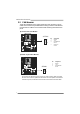
Motherboard Manual CHAPTER 2: HARDWARE INSTALLATION 2.1 INST ALLING CENT RAL PROCESSING UNIT (CPU) Special Notice: Remove Pin Cap before installation, and make good preservation for future use. When the CPU is removed, cover the Pin Cap on the empty socket to ensure pin legs won’t be damaged. Pin-Cap Step 1: Pull the socket locking lever out from the socket and then raise the lever up to a 90-degree angle.
45GC-M7G / 945GC Micro 775 Step 2: Look for the triangular cut edge on socket, and the golden dot on CPU should point forwards this triangular cut edge. The CPU will fit only in the correct orientation. Step 2-1: Step 2-2: Step 3: Hold the CPU down firmly, and then lower the lever to locked position to complete the installation. Step 4: Put the CPU Fan and heatsink assembly on the CPU and buckle it on the retention frame. Connect the CPU FAN power cable into the JCFAN1. This completes the installation.
Motherboard Manual 2.2 FAN HEADERS These fan headers support cooling-fans built in the computer. The fan cable and connector may be different according to the fan manufacturer. Connect the fan cable to the connector while matching the black wire to pin#1.
945GC-M7G / 945GC Micro 775 2.3 INST ALLING SYST EM MEMORY DDR2_B1 DDR2_A1 A. DDR2 module 1. Unlock a DIMM slot by pressing the retaining clips outward. Align a DIMM on the slot such that the notch on the DIMM matches the break on the Slot. 2. Insert the DIMM vertically and firmly into the slot until the retaining chip snap back in place and the DIMM is properly seated. B.
Motherboard Manual C. Dual Channel Memory installation To trigger the Dual Channel f unction of the motherboard, the memory module must meet the following requirements: Install memory module of the same density in pairs, shown in the f ollowing table. Dual Channel Status DDR2_A1 DDR2_B1 Disabled O X Disabled X O Enabled O O (O means memory installed, X means memory not installed.
945GC-M7G / 945GC Micro 775 2.4 CONNECT ORS AND SLOT S FDD1: Floppy Disk Conne ctor The motherboard prov ides a standard floppy disk connector that supports 360K, 720K, 1.2M, 1.44M and 2.88M floppy disk ty pes. This connector supports the prov ided f loppy drive ribbon cables. 1 2 33 34 IDE1: Hard Disk Conne ctors The motherboard has a 32-bit Enhanced PCI IDE Controller that prov ides PIO Mode 0~4, Bus Master, and Ultra DMA 33/66/100 functionality.
Motherboard Manual PEX16_1: PCI-Express x16 Slot - PCI-Express 1.0a compliant. - Maximum theoretical realized bandwidth of 4GB/s simultaneously per direction, f or an aggregate of 8GB/s totally. PEX1_1: PCI-Expre ss x1 Slot - PCI-Express 1.0a compliant. - Data transf er bandwidth up to 250MB/s per direction; 500MB/s in total. PCI-Express supports a raw bit-rate of 2.5Gb/s on the data pins. 2X bandwidth ov er the traditional PCI architecture.
945GC-M7G / 945GC Micro 775 CHAPTER 3: HEADERS & JUMPERS SETUP 3.1 HOW T O SET UP JUMPERS The illustration shows how to set up jumpers. When the jumper cap is placed on pins, the jumper is “close”, if not, that means the jumper is “open”. Pin opened 3.2 Pin closed Pin1-2 closed DET AIL SETT INGS JPANEL1: Front Panel Heade r This 16-pin connector includes Power-on, Reset, HDD LED, Power LED, Sleep button, and speaker connections. It allows user to connect the PC case’s f ront panel switch functions.
Motherboard Manual JATXPWR1: ATX Powe r Source Conne ctor This connector allows user to connect 24-pin power connector on the ATX power supply. 24 12 1 13 Pin 1 2 3 4 5 6 7 8 9 10 11 12 13 14 15 16 17 18 19 20 21 22 23 24 Assignment +3.3V +3.3V Ground +5V Ground +5V Ground PW_OK Standby Voltage +5V +12V +12V 2 x 12 Detect +3.3V -12V Ground PS_ON Ground Ground Ground -5V +5V +5V +5V Ground JATXPWR2: ATX Powe r Source Conne ctor By connecting this connector, it will provide +12V to CPU power circuit.
945GC-M7G / 945GC Micro 775 JUSB3/JUSB4: Heade rs for USB 2.0 Ports at Front Panel This motherboard prov ides 2 USB 2.0 headers, which allows user to connect additional USB cable on the PC front panel, and also can be connected with internal USB dev ices, like USB card reader.
Motherboard Manual JSPDIF_O UT: Digital Audio out Conne ctors This connector allows user to connect the PCI bracket SPDIF output header. Pin 1 2 3 1 Assignment +5V SPDIF_OUT 1 Ground 3 JAUDIO F1: Front Panel Audio Heade r This header allows user to connect the front audio output cable with the PC f ront panel. It will disable the output on back panel audio connectors.
945GC-M7G / 945GC Micro 775 JCDIN1: CD-RO M Audio-in Connector This connector allows user to connect the audio source f rom the variaty dev ices, like CD-ROM, DVD-ROM, PCI sound card, PCI TV turner card etc.. Pin 1 1 2 3 4 4 Assignment Left Channel Input Ground Ground Right Channel Input JCMO S1: Cle ar CMOS Heade r By placing the jumper on pin2-3, it allows user to restore the BIOS saf e setting and the CMOS data, please carefully f ollow the procedures to avoid damaging the motherboard.
Motherboard Manual JKBV1: Powe r Source Heade r for PS/2 Ke yboard and Mouse (O ptional) 1 1 3 3 Pin 1-2 Close +5V for PS/2 keyboard and mouse. 1 3 Pin 2-3 close PS/2 keyboard and mouse are powered by +5V standby voltage. Note: In order to support this func tion “Power-on s ystem via keyboar d and mouse”, “JKBV1” jumper cap should be plac ed on Pin 2-3. JUSBV1/JUSBV3_1: Powe r Source Heade rs for USB Ports (O ptional) Pin 1-2 Close: JUSBV1: +5V for USB ports at JRJ45USB1/JUSB2.
945GC-M7G / 945GC Micro 775 JPRNT1: Printe r Port Connector This header allows you to connector printer on the PC.
Motherboard Manual CHAPTER 4: USEFUL HELP 4.1 DRIVER INST ALLAT ION NOT E After you installed your operating system, please insert the Fully Setup Driver CD into your optical drive and install the driver for better system performance. You will see the following window after you insert the CD The setup guide will auto detect your motherboard and operating system. Note: If this window didn’t show up after you ins ert the Driver CD, please use file brows er to locate and execute the file SETUP.
945GC-M7G / 945GC Micro 775 4.2 AWARD BIOS BEEP CODE Beep Sound One long beep followed by two short beeps High-low siren sound Meaning Video card not found or v ideo card memory bad CPU overheated System will shut down automatically One Short beep when system boot-up No error found during POST Long beeps every other second No DRAM detected or install 4.
Motherboard Manual 4.4 TROUBLESHOOT ING Probable Solution 1. Make sure power cable is No power to the system at all securely plugged in. Power light don’t illuminate, f an inside power supply does not turn 2. Replace cable. on. 3. Contact technical support. 2. Indicator light on key board does not turn on. System inoperativ e. Keyboard lights Using even pressure on both ends of are on, power indicator lights are lit, the DIMM, press down firmly until the and hard driv e is spinning.
945GC-M7G / 945GC Micro 775 CHAPTER 5: WARPSPEEDER™ III 5.1 INT RODUCT ION [WarpSpeeder™ III], a new powerful control utility, features three user-friendly functions including Overclock Manager, Overvoltage Manager, and Hardware Monitor. With the Overclock Manager, users can easily adjust the frequency they prefer or they can get the best CPU performance with just one click. The Overvoltage Manager, on the other hand, helps to power up CPU core voltage and Memory voltage.
Motherboard Manual 5.3 INST ALLAT ION 1. Execute the setup execution file, and then the following dialog will pop up. Please click “Next” button and follow the default procedure to install. 2. When you see the following dialog in setup procedure, it means setup is completed. Click “Finish” button. Usage : The following figures are only for reference, the screen printed in this user manual will change according to your motherboard on hand.
945GC-M7G / 945GC Micro 775 5.4 WARPSPEEDER™ III 1. Desktop Icon After the [WarpSpeeder™ III] has been installed, a [WarpSpeeder™ III] icon will appear on the desktop, just like the icon shown below. Now you can launch the [WarpSpeeder™ III] utility simply by double-clicking the desktop icon. 2. Main Panel If you double-click the desktop icon, [WarpSpeeder™ III] will be launched. Please refer to the following figure; the utility’s first window you will see is Main Panel.
Motherboard Manual 3. Overclock/Overvoltage Panel Click the Overclock/Overvoltage button in the Main Panel, the button will be highlighted and the Overclock/Overvoltage Panel will show up as the following figure. As you can see, the Overclock Panel is on the right side, and the Overvoltage Panel is on the left side.
945GC-M7G / 945GC Micro 775 O ve rclock Panel contains these fe atures: a. “Auto-Overclock”: User can click this button and [WarpSpeeder™ III] will set the best and stable performance and frequency automatically. A warning dialog as below will show up to notify you that the system may become unstable, click on “OK” to proceed. Then [WarpSpeeder™ III] utility will execute a series of testing until system fail. Then system will do fail-safe reboot by using Watchdog function.
Motherboard Manual O ve rvoltage Panel contains these fe ature s: a. b. “CPU Voltage”: This function allows user to adjust CPU voltage. increase or “-“ to decrease the CPU voltage. Click on “+” to “Memory Voltage”: This function allows user to adjust Memory voltage. to increase or “-“ to decrease the Memory voltage. Click on “+” 4. Hardware Monitor Panel Click the Hardware Monitor button in Main Panel, the button will be highlighted and the Hardware Monitor panel will show up as the following figure.
945GC-M7G / 945GC Micro 775 5. About Panel Click the “about” button in Main Panel, the button will be highlighted and the About Panel will show up as the following figure. In this panel, you can get model name and detail information in hints of all the chipset that are related to overclocking. You can also get the the version number of [WarpSpeeder™ III] utility.
Motherboard Manual APPENDENCIES: SPEC IN OTHER LANGUAGE GERMAN 945GC-M7G 945GC Micro 775 LGA 775 LGA 775 Intel Core2Duo / Pentium 4 / Pentium D / Intel Core2Duo / Pentium 4 / Pentium D / Celeron D Prozessoren mit bis zu 3,8 GHz Celeron D Prozessoren mit bis zu 3,8 GHz *It is recommended to use processors with 95W *It is recommended to use processors with 95W CPU FSB Chipsatz Grafik Super E/A power consumption. power consumption.
945GC-M7G / 945GC Micro 775 945GC-M7G Audio-Codec 945GC Micro 775 ALC861VD(VER 6.X) / ALC888(VER 5.X) ALC861VD(VER 6.X) / ALC888(VER 5.X) 5.1-Kanal-Audioausgabe (VER 6.X) 5.1-Kanal-Audioausgabe (VER 6.X) 7.1-Kanal-Audioausgabe (VER 5.X) 7.1-Kanal-Audioausgabe (VER 5.
Motherboard Manual FRANCE 945GC-M7G 945GC Micro 775 LGA 775 LGA 775 Processeurs Intel Core2Duo / Pentium 4 / Processeurs Intel Core2Duo / Pentium 4 / Pentium D / Celeron D jusqu'à 3,8 GHz Pentium D / Celeron D jusqu'à 3,8 GHz *It is recommended to use processors with 95W *It is recommended to use processors with 95W UC power consumption. power consumption.
945GC-M7G / 945GC Micro 775 945GC-M7G Codec audio 945GC Micro 775 ALC861VD(VER 6.X) / ALC888(VER 5.X) ALC861VD(VER 6.X) / ALC888(VER 5.X) Sortie audio à 5.1 voies (VER 6.X) Sortie audio à 5.1 voies (VER 6.X) Sortie audio à 7.1 voies (VER 5.X) Sortie audio à 7.1 voies (VER 5.
Motherboard Manual IT ALIAN 945GC-M7G 945GC Micro 775 LGA 775 LGA 775 Processore Intel Core 2Duo / Pe ntium 4 / Processore Intel Core 2Duo / Pe ntium 4 / Pentium D / Celeron D fino a 3.8 GHz Pentium D / Celeron D fino a 3.8 GHz *It is recommended to use processors with 95W *It is recommended to use processors with 95W CPU FSB Chipset Grafica Super I/O power consumption. power consumption.
945GC-M7G / 945GC Micro 775 945GC-M7G 945GC Micro 775 ALC861VD(VER 6.X) / ALC888(VER 5.X) ALC861VD(VER 6.X) / ALC888(VER 5.X) Codec Uscita audio 5.1 ca nali (VER 6.X) Uscita audio 5.1 ca nali (VER 6.X) audio Uscita audio 7.1 ca nali (VER 5.X) Uscita audio 7.1 ca nali (VER 5.
Motherboard Manual SPANISH 945GC-M7G 945GC Micro 775 LGA 775 LGA 775 Procesador Intel Core2Duo / Pentium 4 / Procesador Intel Core2Duo / Pentium 4 / Pentium D / Celeron D hasta 3,8 GHz Pentium D / Celeron D hasta 3,8 GHz *It is recommended to use processors with 95W *It is recommended to use processors with 95W CPU FSB power consumption. power consumption.
945GC-M7G / 945GC Micro 775 945GC-M7G 945GC Micro 775 ALC861VD(VER 6.X) / ALC888(VER 5.X) ALC861VD(VER 6.X) / ALC888(VER 5.X) Códecs de Salida de sonido de 5.1 canales (VER 6.X) Salida de sonido de 5.1 canales (VER 6.X) sonido Salida de sonido de 7.1 canales (VER 5.X) Salida de sonido de 7.1 canales (VER 5.
Motherboard Manual PORT UGUESE 945GC-M7G 945GC Micro 775 LGA 775 LGA 775 Processador Intel Core2Duo / Pentium 4 / Processador Intel Core2Duo / Pentium 4 / Pentium D / Celeron D até 3,8 GHz Pentium D / Celeron D até 3,8 GHz *It is recommended to use processors with 95W *It is recommended to use processors with 95W CPU power consumption. power consumption.
945GC-M7G / 945GC Micro 775 945GC-M7G 945GC Micro 775 ALC861VD(VER 6.X) / ALC888(VER 5.X) ALC861VD(VER 6.X) / ALC888(VER 5.X) Codec de Saída de áudio de 5.1 canais (VER 6.X) Saída de áudio de 5.1 canais (VER 6.X) som Saída de áudio de 7.1 canais (VER 5.X) Saída de áudio de 7.1 canais (VER 5.
Motherboard Manual POLISH 945GC-M7G LGA 775 945GC Micro 775 LGA 775 Procesor Intel Core2Duo / Pentium 4 / Pentium D Procesor Intel Core2Duo / Pentium 4 / Pentium D / Celeron D do 3,8 GHz / Celeron D do 3,8 GHz *It is recommended to use processors with 95W *It is recommended to use processors with 95W Procesor power consumption. Obsługa Hyper-Threading Execute Disable Bit Execute Disable Bit Enhanced Intel SpeedStep® Extended Memory 64 Technology FSB Chipset Grafika power consumption.
945GC-M7G / 945GC Micro 775 945GC-M7G 945GC Micro 775 ALC861VD(VER 6.X) / ALC888(VER 5.X) ALC861VD(VER 6.X) / ALC888(VER 5.X) 5.1 kanałowe wyjście audio (VER 6.X) 5.1 kanałowe wyjście audio (VER 6.X) dźwiękowy 7.1 kanałowe wyjście audio (VER 5.X) 7.1 kanałowe wyjście audio (VER 5.
Motherboard Manual RUSSIAN 945GC-M7G CPU (центральн ый процессор) 945GC Micro 775 LGA 775 LGA 775 Процессор Intel Core2Duo / Pentium 4 / Процессор Intel Core2Duo / Pentium 4 / Pentium D / Celeron D до 3.8 ГГц Pentium D / Celeron D до 3.8 ГГц *It is recommended to use processors with 95W *It is recommended to use processors with 95W power consumption. power consumption.
945GC-M7G / 945GC Micro 775 945GC-M7G 945GC Micro 775 ALC861VD(VER 6.X) / ALC888(VER 5.X) ALC861VD(VER 6.X) / ALC888(VER 5.X) Звуковой 5.1канальный звуковой выход (VER 6.X) 5.1канальный звуковой выход (VER 6.X) кодек 7.1канальный звуковой выход (VER 5.X) 7.1канальный звуковой выход (VER 5.
Motherboard Manual ARABIC 945GC-M7G LGA 775 945GC Micro 775 LGA 775 Intel Core2Duo / Pentium 4 / Pentium D /ﻡﻌ ﺎﻟﺠﺎت Intel Core2Duo / Pentium 4 / Pentium D /ﻡﻌ ﺎﻟﺠﺎت ﺑ ﺘﺮدد ﻳﺼﻞ إﻟﻰ 3.8ﺝﻴﺠﺎ هﺮﺕﺰCeleron D وﺣﺪة اﻟﻤﻌ ﺎﻟﺠﺔ اﻟﻤﺮآﺰﻳﺔ *It is recommended to use processors with 95W *It is recommended to use processors with 95W power consumption. power consumption.
945GC-M7G / 945GC Micro 775 945GC-M7G آﻮدﻳﻚ اﻟﺼﻮت 945GC Micro 775 )ALC861VD(VER 6.X) / ALC888(VER 5.X )ALC861VD(VER 6.X) / ALC888(VER 5.X ) (VER 6.Xﻗﻨﻮات ﻟﺨﺮج اﻟﺼﻮت5.1 ) (VER 6.Xﻗﻨﻮات ﻟﺨﺮج اﻟﺼﻮت5.1 ) (VER 5.Xﻗﻨﻮات ﻟﺨﺮج اﻟﺼﻮت7.1 ) (VER 5.Xﻗﻨﻮات ﻟﺨﺮج اﻟﺼﻮت7.
Motherboard Manual JAPANESE 945GC-M7G 945GC Micro 775 LGA 775 LGA 775 Intel Core2Duo / Pentium 4 / Pentium D / Intel Core2Duo / Pentium 4 / Pentium D / Celeron D processor up to 3.8 GHz Celeron D processor up to 3.8 GHz *It is recommended to use processors with 95W *It is recommended to use processors with 95W CPU FSB チップセット power consumption. power consumption.
945GC-M7G / 945GC Micro 775 945GC-M7G サウンド Codec スロット ALC861VD(VER 6.X) / ALC888(VER 5.X) 5.1チャンネルオーディオアウト(VER 6.X) 5.1チャンネルオーディオアウト(VER 6.X) 7.1チャンネルオーディオアウト(VER 5.X) 7.1チャンネルオーディオアウト(VER 5.