A785G3/A780L3/A780L3G Setup Manual FCC Information and Copyright This equipment has been tested and found to comply with the limits of a Class B digital device, pursuant to Part 15 of the FCC Rules. These limits are designed to provide reasonable protection against harmful interference in a residential installation.
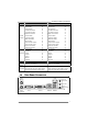
Table of Contents Chapter 1: Introduction ............................................................ 1 1.1 Before You Start ................................................................................ 1 1.2 Package Checklist ............................................................................. 1 1.3 Motherboard Features...................................................................... 2 1.4 Rear Panel Connectors ..................................................................... 3 1.
A785G3/A780L3/A780L3G CHAPTER 1: INTRODUCTION 1.1 BEFORE YOU START Thank you for choosing our product. Before you start installing the motherboard, please make sure you follow the instructions below: 1.2 Prepare a dry and stable working environment with sufficient lighting. Always disconnect the computer from power outlet before operation.
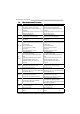
Motherboard Manual 1.3 MOTHERBOARD FEATURES A785G3 CPU A780L3/A780L3G Socket AM3 Socket AM3 AMD Phenom II/ Athlon II processors AMD Phenom II/ Athlon II processors AMD 64 Architecture enables 32 and 64 bit AMD 64 Architecture enables 32 and 64 bit computing computing Supports Hyper Transport 3.0 and Cool=n=Quiet Supports Hyper Transport 3.0 and Cool=n=Quiet FSB Chipset (Maximum Watt: 125W) (Maximum Watt: 125W) Support HyperTransport 3.0 Support HyperTransport 3.0 Supports up to 5.
A785G3/A780L3/A780L3G A785G3 A780L3/A780L3G Floppy Connector x1 Floppy Connector IDE Connector x1 IDE Connector x1 x1 SATA Connector x4 SATA Connector x4 Front Panel Connector x1 Front Panel Connector x1 Front Audio Connector x1 Front Audio Connector x1 S/PDIF Out Connector x1 S/PDIF Out Connector x1 On Board CPU Fan Header x1 CPU Fan Header x1 Connector System Fan Header x1 System Fan Header x1 CMOS clear Header x1 CMOS clear Header x1 USB Connector x2 USB Connector
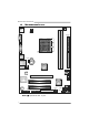
Motherboard Manual 1.5 MOTHERBOARD LAYOUT KBMS1 CPU_FAN1 ATXPWR2 ATXPWR1 VGA 1 D D R 3 _A 1 AM 3 D D R 3 _B1 S oc ket DV I1 IDE1 USB1 JUSBV1 BAT1 RJ45USB1 AMD 785G/ 780L AUDIO1 JSPDIFOUT1 SATA4 LAN SATA3 PEX16_1 BIOS Super I/O JCMOS1 PCI1 AMD SB710 PCI2 SATA2 F_USB2 Codec J_COM1 J_PRINT1 FDD1 F_AUDIO1 Note: ■ represents the 1st pin.
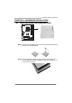
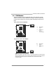
A785G3/A780L3/A780L3G CHAPTER 2: HARDWARE INSTALLATION 2.1 INSTALLING CENTRAL PROCESSING UNIT (CPU) Step 1: Pull the lever toward direction A from the socket and then raise the lever up to a 90-degree angle. Step 2: Look for the white triangle on socket, and the gold triangle on CPU should point towards this white triangle. The CPU will fit only in the correct orientation.
Motherboard Manual Step 3: Hold the CPU down firmly, and then close the lever toward direct B to complete the installation. Step 4: Put the CPU Fan on the CPU and buckle it. Connect the CPU FAN power cable to the CPU_FAN1. This completes the installation.
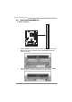
A785G3/A780L3/A780L3G 2.2 FAN HEADERS These fan headers support cooling-fans built in the computer. The fan cable and connector may be different according to the fan manufacturer. Connect the fan cable to the connector while matching the black wire to pin#1. CPU_FAN1: CPU Fan Header 1 4 Pin 1 2 3 4 Assignment Ground +12V FAN RPM rate sense Smart Fan Control (By Fan) SYS_FAN1: System Fan Header Pin 1 2 3 1 Assignment Ground +12V FAN RPM rate sense 3 Note: CPU_FAN1 supports 4-pin head connector.
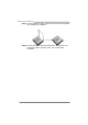
Motherboard Manual 2.3 INSTALLING SYSTEM MEMORY D D R 3 _A1 DD R 3 _ B 1 A. Memory Modules 8 1. Unlock a DIMM slot by pressing the retaining clips outward. Align a DIMM on the slot such that the notch on the DIMM matches the break on the Slot. 2. Insert the DIMM vertically and firmly into the slot until the retaining chip snap back in place and the DIMM is properly seated.
A785G3/A780L3/A780L3G B. Memory Capacity DIMM Socket Location DDR3 Module DDR3_A1 512MB/1GB/2GB/4GB DDR3_B1 512MB/1GB/2GB/4GB Total Memory Size Max is 8GB. C. Dual Channel Memory installation Please refer to the following requirements to activate Dual Channel function: Install memory module of the same density in pairs, shown in the table Dual Channel Status DDR3_A1 DDR3_B1 Disabled X O Disabled O X Enabled O O (O means memory installed, X means memory not installed.
Motherboard Manual 2.4 CONNECTORS AND SLOTS FDD1: Floppy Disk Connector The motherboard provides a standard floppy disk connector that supports 360K, 720K, 1.2M, 1.44M and 2.88M floppy disk types. 2 34 1 33 IDE1: Hard Disk Connector The motherboard has a 32-bit Enhanced PCI IDE Controller that provides PIO Mode 0~4, Bus Master, and Ultra DMA 33/66/100/133 functionality.
A785G3/A780L3/A780L3G ATXPWR1: ATX Power Source Connector This connector allows user to connect 24-pin power connector on the ATX power supply. 12 24 1 13 Pin Assignment Pin Assignment 13 14 15 16 17 18 19 20 21 22 23 24 +3.3V -12V Ground PS_ON Ground Ground Ground NC +5V +5V +5V Ground 1 2 3 4 5 6 7 8 9 10 11 12 +3.3V +3.3V Ground +5V Ground +5V Ground PW_OK Standby Voltage+5V +12V +12V +3.3V ATXPWR2: ATX Power Source Connector Connecting this connector will provide +12V to CPU power circuit.
Motherboard Manual PEX16_1: PCI-Express Gen2 x16 Slot - PCI-Express 2.0 compliant. Maximum theoretical realized bandwidth of 8GB/s simultaneously per direction, for an aggregate of 16GB/s totally. PEX16_1 PCI1~PCI2: Peripheral Component Interconnect Slots This motherboard is equipped with 2 standard PCI slots. PCI stands for Peripheral Component Interconnect, and it is a bus standard for expansion cards. This PCI slot is designated as 32 bits.
A785G3/A780L3/A780L3G CHAPTER 3: HEADERS & JUMPERS SETUP 3.1 HOW TO SETUP JUMPERS The illustration shows how to set up jumpers. When the jumper cap is placed on pins, the jumper is “close”, if not, that means the jumper is “open”. Pin opened 3.2 Pin closed Pin1-2 closed DETAIL SETTINGS PANEL1: Front Panel Header This 16-pin connector includes Power-on, Reset, HDD LED, Power LED, and speaker connection. It allows user to connect the PC case’s front panel switch functions.
Motherboard Manual F_USB1/F_USB2: Headers for USB 2.0 Ports at Front Panel This header allows user to connect additional USB cable on the PC front panel, and also can be connected with internal USB devices, like USB card reader. F_USB2 F _ U SB1 9 1 10 2 Assignment +5V (fused) +5V (fused) USBUSBUSB+ USB+ Ground Ground NC Key Pin 1 2 3 4 5 6 7 8 9 10 JUSBV1/JUSBV2: Power Source Headers for USB Ports Pin 1-2 Close: JUSBV1: +5V for USB ports at USB1/RJ45USB1. JUSBV2: +5V for USB ports at F_USB1/F_USB2.
A785G3/A780L3/A780L3G JSPDIFOUT1: Digital Audio-out Connector This connector allows user to connect the PCI bracket SPDIF output header. Pin 1 2 3 3 Assignment +5V SPDIF_OUT Ground 1 F_AUDIO1: Front Panel Audio Header This header allows user to connect the front audio output cable with the PC front panel. This header allows only HD audio front panel connector; AC’97 connector is not acceptable.
Motherboard Manual JCMOS1: Clear CMOS Header Placing the jumper on pin2-3, it allows user to restore the BIOS safe setting and the CMOS data. Please carefully follow the procedures to avoid damaging the motherboard. 1 3 Pin 1-2 Close: Normal Operation (default). 1 1 3 3 Pin 2-3 Close: Clear CMOS data. ※ Clear CMOS Procedures: 1. 2. 3. 4. 5. 6. Remove AC power line. Set the jumper to “Pin 2-3 close”. Wait for five seconds. Set the jumper to “Pin 1-2 close”. Power on the AC.
A785G3/A780L3/A780L3G J_PRINT1: Printer Port Connector This header allows you to connector printer on the PC.
Motherboard Manual CHAPTER 4: RAID FUNCTIONS 4.1 OPERATING SYSTEM Supports Windows XP, Windows Vista, and Windows 7. 4.2 RAID ARRAYS RAID supports the following types of RAID arrays: RAID 0: RAID 0 defines a disk striping scheme that improves disk read and write times for many applications. RAID 1: RAID 1 defines techniques for mirroring data. RAID 1+0: RAID 1+0 combines the techniques used in RAID 0 and RAID 1. 4.
A785G3/A780L3/A780L3G RAID 1: Every read and write is actually carried out in parallel across 2 disk drives in a RAID 1 array system. The mirrored (backup) copy of the data can reside on the same disk or on a second redundant drive in the array. RAID 1 provides a hot-standby copy of data if the active volume or drive is corrupted or becomes unavailable because of a hardware failure.
Motherboard Manual RAID 1+0: RAID 1 drives can be stripped using RAID 0 techniques. Resulting in a RAID 1+0 solution for improved resiliency, performance and rebuild performance. Features and Benefits - - Drives: Minimum 4, and maximum is 6 or 8, depending on the platform. Benefits: Optimizes for both fault tolerance and performance, allowing for automatic redundancy. May be simultaneously used with other RAID levels in an array, and allows for spare disks.
A785G3/A780L3/A780L3G CHAPTER 5: USEFUL HELP 5.1 DRIVER INSTALLATION NOTE After you installed your operating system, please insert the Fully Setup Driver CD into your optical drive and install the driver for better system performance. You will see the following window after you insert the CD The setup guide will auto detect your motherboard and operating system. Note: If this window didn’t show up after you insert the Driver CD, please use file browser to locate and execute the file SETUP.
Motherboard Manual 5.2 SOFTWARE Installing Software 1. Insert the Setup CD to the optical drive. The drivers installation program would appear if the Autorun function has been enabled. 2. Select Software Installation, and then click on the respective software title. 3. Follow the on-screen instructions to complete the installation. Launching Software After the installation process, you will see the software icon “eHOT Line” / “BIOS Update” appears on the desktop.
A785G3/A780L3/A780L3G After filling up this information, click “Send” to send the mail out. A warning dialog would appear asking for your confirmation; click “Send” to confirm or “Do Not Send” to cancel. If you want to save this information to a .txt file, click “Save As…” and then you will see a saving dialog appears asking you to enter file name. Enter the file name and then click “Save”. Your system information will be saved to a .txt file. Open the saved .
Motherboard Manual BIOS Update BIOS Update is a convenient utility which allows you to update your motherboard BIOS under Windows system. AWARD BIOS Show current BIOS information AMI BIOS Clear CMOS function (Only for AWARD BIOS) Save current BIOS to a .bin file Update BIOS with a BIOS file Once click on this button, the saving dialog will show. Choose the position to save file and enter file name.
A785G3/A780L3/A780L3G Before doing this, please download the proper BIOS file from the website. For AWARD BIOS, update BIOS procedure should be run with Clear CMOS function, so please check on Clear CMOS first. Then click Update BIOS button, a dialog will show for asking you backup current BIOS. Click Yes for BIOS backup and refer to the Backup BIOS procedure; or click No to skip this procedure.
Motherboard Manual 5.3 EXTRA INFORMATION CPU Overheated If the system shutdown automatically after power on system for seconds, that means the CPU protection function has been activated. When the CPU is over heated, the motherboard will shutdown automatically to avoid a damage of the CPU, and the system may not power on again. In this case, please double check: 1. The CPU cooler surface is placed evenly with the CPU surface. 2. CPU fan is rotated normally. 3.
A785G3/A780L3/A780L3G BIO-Flasher BIO-Flasher is a BIOS flashing utility providing you an easy and simple way to update your BIOS via USB pen drive or floppy disk. The BIO-Flasher is built in the BIOS chip. To enter the utility, press during the Power-On Self Tests (POST) procedure while booting up. Updating BIOS with BIO-Flasher 1. Go to the website to download the latest BIOS file for the motherboard. 2. Then, save the BIOS file into a USB pen drive or a floppy disk. 3.
Motherboard Manual 5.4 AMI BIOS BEEP CODE Boot Block Beep Codes Number of Beeps 1 2 3 4 5 7 10 11 12 13 Description No media present. (Insert diskette in floppy drive A:) “AMIBOOT.ROM” file not found in root directory of diskette in A: Insert next diskette if multiple diskettes are used for recovery Flash Programming successful File read error No Flash EPROM detected Flash Erase error Flash Program error “AMIBOOT.
A785G3/A780L3/A780L3G 5.5 TROUBLESHOOTING Probable 1. There is no power in the system. Power LED does not shine; the fan of the power supply does not work 2. Indicator light on keyboard does not shine. System is inoperative. Keyboard lights are on, power indicator lights are lit, and hard drives are running. System does not boot from a hard disk drive, but can be booted from optical drive. Solution 1. 2. 3. Make sure power cable is securely plugged in. Replace cable. Contact technical support.
Motherboard Manual APPENDIX: SPEC IN OTHER LANGUAGES GERMAN A785G3 CPU A780L3/A780L3G Sockel AM3 Sockel AM3 AMD Phenom II/ Athlon II Prozessoren AMD Phenom II/ Athlon II Prozessoren Die AMD 64-Architektur unterstützt eine 32-Bit- Die AMD 64-Architektur unterstützt eine 32-Bitund 64-Bit-Datenverarbeitung und 64-Bit-Datenverarbeitung Unterstützt Hyper Transport 3.0 und Cool’n’Quiet Unterstützt Hyper Transport 3.
A785G3/A780L3/A780L3G A785G3 HD A780L3/A780L3G ALC662 ALC662 Audio-Unters 5.
Motherboard Manual FRENCH A785G3 A780L3/A780L3G Socket AM3 Socket AM3 Processeurs AMD Phenom II/ Athlon II Processeurs AMD Phenom II/ Athlon II L'architecture AMD 64 permet le calcul 32 et 64 L'architecture AMD 64 permet le calcul 32 et 64 UC Bus frontal Chipset Super E/S Mémoire principale bits bits Prend en charge Hyper Transport 3.0 et Prend en charge Hyper Transport 3.0 et Cool’n’Quiet Cool’n’Quiet (Watt maximum : 125W) (Watt maximum : 125W) Prend en charge Hyper Transport 3.
A785G3/A780L3/A780L3G A785G3 A780L3/A780L3G Prise en ALC662 ALC662 charge Sortie audio à 5.1 voies Sortie audio à 5.
Motherboard Manual ITALIAN A785G3 CPU FSB Chipset A780L3/A780L3G Socket AM3 Socket AM3 Processori AMD Phenom II/ Athlon II Processori AMD Phenom II/ Athlon II L’architettura AMD 64 abilita la L’architettura AMD 64 abilita la computazione 32 e 64 bit computazione 32 e 64 bit Supporto di Hyper Transport 3.0 e Supporto di Hyper Transport 3.0 e Cool’n’Quiet Cool’n’Quiet (Watt massimo: 125W) (Watt massimo: 125W) Supporto di HyperTransport 3.0 fino a 5.2 Supporto di HyperTransport 3.
A785G3/A780L3/A780L3G A785G3 Supporto audio HD Alloggi A780L3/A780L3G ALC662 ALC662 Uscita audio 5.1 canali Uscita audio 5.
Motherboard Manual SPANISH A785G3 A780L3/A780L3G Conector AM3 Conector AM3 Procesadores AMD Phenom II/ Athlon II Procesadores AMD Phenom II/ Athlon II La arquitectura AMD 64 permite el procesado de La arquitectura AMD 64 permite el procesado de CPU FSB 32 y 64 bits 32 y 64 bits Soporta las tecnologías Hyper Transport 3.0 y Soporta las tecnologías Hyper Transport 3.0 y Cool’n’Quiet Cool’n’Quiet (Vatio máximo: 125W) (Vatio máximo: 125W) Admite HyperTransport 3.
A785G3/A780L3/A780L3G A785G3 Soporte de sonido HD Ranuras A780L3/A780L3G ALC662 ALC662 Salida de sonido de 5.1 canales Salida de sonido de 5.
Motherboard Manual PORTUGUESE A785G3 CPU FSB A780L3/A780L3G Socket AM3 Socket AM3 Processadores AMD Phenom II/ Athlon II Processadores AMD Phenom II/ Athlon II A arquitectura AMD 64 permite uma A arquitectura AMD 64 permite uma computação de 32 e 64 bits computação de 32 e 64 bits Suporta as tecnologias Hyper Transport 3.0 e Suporta as tecnologias Hyper Transport 3.0 e Cool’n’Quiet Cool’n’Quiet (Watt máximo: 125W) (Watt máximo: 125W) Suporta a tecnologia HyperTransport 3.
A785G3/A780L3/A780L3G A785G3 Suporte para áudio de alta definição Ranhuras A780L3/A780L3G ALC662 ALC662 Saída de áudio de 5.1 canais Saída de áudio de 5.
Motherboard Manual POLISH A785G3 Procesor FSB Chipset A780L3/A780L3G Socket AM3 Socket AM3 AMD Phenom II/ Athlon II Procesory AMD Phenom II/ Athlon II Procesory Architektura AMD 64 umożliwia przetwarzanie Architektura AMD 64 umożliwia przetwarzanie 32 i 64 bitowe 32 i 64 bitowe Obsługa Hyper Transport 3.0 oraz Cool’n’Quiet Obsługa Hyper Transport 3.0 oraz Cool’n’Quiet (Maksymalny Watt: 125W) (Maksymalny Watt: 125W) Obsługa HyperTransport 3.0 o szerokości pasma Obsługa HyperTransport 3.
A785G3/A780L3/A780L3G A785G3 Obsługa audio HD Gniazda Złącza wbudowan e Back Panel I/O Wymiary płyty Funkcje A780L3/A780L3G ALC662 ALC662 5.1 kanałowe wyjście audio 5.
Motherboard Manual RUSSIAN A785G3 Гнездо AM3 Процессоры AMD Phenom II/ Athlon II CPU Архитектура AMD 64 разрешать обработка (центральны данных на 32 и 64 бит й процессор) Поддержка Hyper Transport 3.0 и Cool’n’Quiet (Максимальный ватт: 125W) FSB A780L3/A780L3G Гнездо AM3 Процессоры AMD Phenom II/ Athlon II Архитектура AMD 64 разрешать обработка данных на 32 и 64 бит Поддержка Hyper Transport 3.0 и Cool’n’Quiet (Максимальный ватт: 125W) Поддержка HyperTransport 3.0 с пропускной Поддержка HyperTransport 3.
A785G3/A780L3/A780L3G A785G3 A780L3/A780L3G Звуковая поддержка жесткого диска ALC662 Звуковая поддержка High-Definition 5.1канальный звуковой выход ALC662 Звуковая поддержка High-Definition 5.
Motherboard Manual ARABIC A785G3 وﺡﺪة اﻟﻤﻌﺎﻟﺠﺔ اﻟﻤﺮآﺰیﺔ A780L3/A780L3G AM3ﻣﻘﺒﺲ AM3ﻣﻘﺒﺲ Aﻣﻘﺒﺲ AMD Phenom II/ Athlon IIﻣﻌﺎﻟﺠﺎت AMD Phenom II/ Athlon IIﻣﻌﺎﻟﺠﺎت إﺝﺮاء اﻟﻌﻤﻠﻴﺎت اﻟﺤﺎﺳﻮﺏﻴﺔ ﺏﺴﺮﻋﺔ 32و 64ﺏﺖAMD 64ﺗﻤﻜﻦ ﺗﻘﻨﻴﺔ إﺝﺮاء اﻟﻌﻤﻠﻴﺎت اﻟﺤﺎﺳﻮﺏﻴﺔ ﺏﺴﺮﻋﺔ 32و 64ﺏﺖAMD 64ﺗﻤﻜﻦ ﺗﻘﻨﻴﺔ Cool’n’Quietو Hyper Transport 3.0ﺗﺪﻋﻢ ﺗﻘﻨﻴﺔ Cool’n’Quietو Hyper Transport 3.0ﺗﺪﻋﻢ ﺗﻘﻨﻴﺔ )و: 125ﻗﺼ ﻮى واط( )و: 125ﻗﺼ ﻮى واط( اﻟﻨﺎﻗﻞ اﻷﻣﺎﻣﻲ اﻟﺠﺎﻥﺒﻲ 5.
A785G3/A780L3/A780L3G A785G3 دﻋﻢ اﻟﺼﻮت ﻋﺎﻟﻲ اﻟﺘﻌﺮیﻒ A780L3/A780L3G ALC662 ALC662 ﻗﻨﻮات ﻟﺨﺮج اﻟﺼﻮت5.1 ﻗﻨﻮات ﻟﺨﺮج اﻟﺼﻮت5.
Motherboard Manual JAPANESE A785G3 A780L3/A780L3G Socket AM3 Socket AM3 AMD Phenom II/ Athlon II プロセッサ AMD Phenom II/ Athlon II プロセッサ AMD 64アーキテクチャでは、32ビットと64ビット計 AMD 64アーキテクチャでは、32ビットと64ビット計 CPU FSB 算が可能です 算が可能です ハイパートランスポート3.0とクールアンドクワイア ハイパートランスポート3.0とクールアンドクワイア ットをサポートします ットをサポートします (最高のワット: 125W) (最高のワット: 125W) 5.2 GT/sのバンド幅までハイパートランスポート3.0 5.2 GT/sのバンド幅までハイパートランスポート3.
A785G3/A780L3/A780L3G A785G3 A780L3/A780L3G HDオーディ ALC662 ALC662 オのサポー 5.1チャンネルオーディオアウト 5.