A75MD+/ A78MD Setup Manual FCC Information and Copyright This equipment has been tested and found to comply with the limits of a Class B digital device, pursuant to Part 15 of the FCC Rules. These limits are designed to provide reasonable protection against harmful interference in a residential installation. This equipment generates, uses, and can radiate radio frequency energy and, if not installed and used in accordance with the instructions, may cause harmful interference to radio communications.
Table of Contents Chapter 1: Introduction ...............................................................1 1.1 1.2 1.3 1.4 1.5 Before You Start......................................................................... 1 Package Checklist ..................................................................... 1 Motherboard Specifications ....................................................... 2 Rear Panel Connectors ............................................................. 3 Motherboard Layout ...........
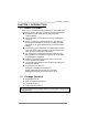
A75MD+/A78MD CHAPTER 1: INTRODUCTION 1.1 Before You Start Thank you for choosing our product. Before you start installing the motherboard, please make sure you follow the instructions below: Prepare a dry and stable working environment with sufficient lighting. Always disconnect the computer from power outlet before operation.
Motherboard Manual 1.3 Motherboard Specifications Specifications 2 CPU Support Socket FM2+/FM2 for AMD A-series processor Maximum CPU TDP (Thermal Design Power): 100Watt * Please refer to www.biostar.com.tw for CPU support list. Chipset A75MD+: AMD A75 FCH A78MD: AMD A78 FCH Memory Supports Dual Channel DDR3 800/ 1066/ 1333/ 1600/ 1866/ 2133/ 2400(OC)/ 2600(OC) 2 x DDR3 DIMM Memory Slot, Max.
A75MD+/A78MD 1.4 Note 1: Note 2: Note 3: Note 4: Rear Panel Connectors DVI-D / VGA Output require an AMD family processor with intedrated graphics. The mainboard supports two independent display outputs. Since the audio chip supports High Definition Audio Specification, the function of each audio jack can be defined by software. The input / output function of each audio jack listed above represents the default setting.
Motherboard Manual 1.5 Motherboard Layout Note: ■ represents the 1st pin.
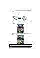
A75MD+/A78MD CHAPTER 2: HARDWARE INSTALLATION 2.1 Install Central Processing Unit (CPU) Step 1: Locate the CPU socket on the motherboard Step 2: Pull the socket locking out from the socket and then raise the lever up to a 90-degree angel. Step 3: Look for the white triangle on socket, and the gold triangle on CPU should point towards this white triangle. The CPU will fit only in the correct orientation.
Motherboard Manual Step 4: Hold the CPU down firmly, and then close the lever to locked the position 2.2 Install a Heatsink Step 1: Place the heatsink and fan assembly onto the retention frame. Match the heatsink clip with the socket mounting-lug. Hook the spring clip to the mounting-lug. Step 2: On the other side, push the retention clip straight down to lock into the plastic lug on the retention frame, and then press down the locker until it stops.
A75MD+/A78MD 2.3 Connect Cooling Fans These fan headers support cooling-fans built in the computer. The fan cable and connector may be different according to the fan manufacturer. Connect the fan cable to the connector while matching the black wire to pin#1.
Motherboard Manual 2.4 Install System Memory A. DDR3 Modules Step 1: Unlock a DIMM slot by pressing the retaining clips outward. Align a DIMM on the slot such that the notch on the DIMM matches the break on the slot. Step 2: Insert the DIMM vertically and firmly into the slot until the retaining clips snap back in place and the DIMM is properly seated. Note: If the DIMM does not go in smoothly, do not force it. Pull it all the way out and try again.
A75MD+/A78MD B. Memory Capacity DIMM Socket Location DDR3 Module DDR3_A1 512MB/1GB/2GB/4GB/8GB/16GB DDR3_B1 512MB/1GB/2GB/4GB/8GB/16GB Total Memory Size Max is 32GB. C. Dual Channel Memory Installation Please refer to the following requirements to activate Dual Channel function: Install memory module of the same density in pairs, shown in the table. Dual Channel Status DDR3_A1 DDR3_B1 Disabled O X Disabled X O Enabled O O (O means memory installed, X means memory not installed.
Motherboard Manual 2.5 Expansion Slots PEX16_1: PCI-Express Gen3 x16 Slot - PCI-Express 3.0 compliant. Maximum theoretical realized bandwidth of 16GB/s simultaneously per direction, for an aggregate of 32GB/s totally. Only FM2+ processors can support PCIe 3.0. PEX1_1: PCI-Express Gen2 x1 Slot - PCI-Express 2.0 compliant. Data transfer bandwidth up to 500MB/s per direction; 1GB/s in total Install an Expansion Card You can install your expansion card by following steps: 1.
A75MD+/A78MD 2.6 Jumper Setting The illustration shows how to set up jumpers. When the jumper cap is placed on pins, the jumper is “close”, if not, that means the jumper is “open”. Pin opened Pin closed Pin1-2 closed JCMOS1: Clear CMOS Header Placing the jumper on pin2-3, it allows user to restore the BIOS safe setting and the CMOS data. Please carefully follow the procedures to avoid damaging the motherboard. 3 1 Pin 1-2 Close: Normal Operation (default). 3 1 Pin 2-3 Close: Clear CMOS data.
Motherboard Manual 2.7 Headers & Connectors ATXPWR1: ATX Power Source Connector For better compatibility, we recommend to use a standard ATX 24-pin power supply for this connector. Make sure to find the correct orientation before plugging the connector. Pin 13 14 15 16 17 18 19 20 21 22 23 24 Assignment +3.3V -12V Ground PS_ON Ground Ground Ground NC +5V +5V +5V Ground Pin 1 2 3 4 5 6 7 8 9 10 11 12 Assignment +3.3V +3.3V Ground +5V Ground +5V Ground PW_OK Standby Voltage+5V +12V +12V +3.
A75MD+/A78MD JPANEL1: Front Panel Header This 16-pin header includes Power-on, Reset, HDD LED, Power LED, and speaker connection. It allows user to connect the PC case’s front panel switch functions.
Motherboard Manual JFRONT_USB3_1: Header for USB 3.0 Ports at Front Panel This header allows user to add additional USB ports on the PC front panel, and also can be connected with a wide range of external peripherals. Pin 1 2 3 4 5 6 7 8 9 10 Assignment VBUS0 SSRX1SSRX1+ Ground SSTX1SSTX1+ Ground D1D1+ ID Pin 11 12 13 14 15 16 17 18 19 20 Assignment D2+ D2Ground SSTX2+ SSTX2Ground SSRX2+ SSRX2VBUS1 Key F_USB1/F_USB2: Headers for USB 2.
A75MD+/A78MD F_AUDIO1: Front Panel Audio Header This header allows user to connect the front audio output cable with the PC front panel. This header supports HD and AC’97 audio front panel connector.
Motherboard Manual CHAPTER 3: UEFI BIOS & SOFTWARE 3.1 3.2 UEFI BIOS Setup For better system performance, the UEFI BIOS firmware is being continuously updated. The UEFI BIOS information described below in this manual is for your reference only and the actual UEFI BIOS information and settings on board may be different from this manual For further information of setting up the UEFI BIOS, please refer to the UEFI BIOS Manual in the Setup DVD.
A75MD+/A78MD 6. After the BIOS Update process is finished, click on OK to reboot the system. 7. While the system boots up and the full screen logo shows up, please press the key to enter BIOS setup. After entering the BIOS setup, please go to the Save & Exit, using the Restore Defaults function to load Optimized Defaults, and select Save Changes and Reset to restart the computer. Then, the BIOS Update is completed.
Motherboard Manual 2. Online Update Utility 1. Installing BIOS Update Utility from the DVD Driver. 2. Please make sure the system is connected to the internet before using this function. 3. Open BIOS Update Utility and click the Online Update button on the main screen. 4. An open dialog will show up to request your agreement to start the BIOS update. Click Yes to start the online update procedure. 5. If there is a new BIOS version, the utility will ask you to download it. Click Yes to proceed. 6.
A75MD+/A78MD 8. While the system boots up and the full screen logo shows up, press key to enter BIOS setup. After entering the BIOS setup, please go to the Save & Exit, using the Restore Defaults function to load Optimized Defaults, and select Save Changes and Reset to restart the computer. Then, the BIOS Update is completed. 3. BIOSTAR BIOS Flasher BIOSTAR BIOS Flasher is a BIOS flashing utility providing you an easy and simple way to update your BIOS via USB pen drive.
Motherboard Manual 6. Select the proper BIOS file, and a message asking if you are sure to flash the BIOS file. Click Yes to start updating BIOS. 7. A dialog pops out after BIOS flash is completed, asking you to restart the system. Press the [Y] key to restart system. 8. While the system boots up and the full screen logo shows up, press key to enter BIOS setup.
A75MD+/A78MD 3.3 Software Installing Software 1. Insert the Setup DVD to the optical drive. The driver installation program would appear if the Autorun function has been enabled. 2. Select Software Installation, and then click on the respective software title. 3. Follow the on-screen instructions to complete the installation. Note1: All the information and content about following software are subject to be changed without notice. For better performance, the software is being continuously updated.
Motherboard Manual After filling up this information, click “Send” to send the mail out. A warning dialog would appear asking for your confirmation; click “Send” to confirm or “Do Not Send” to cancel. If you want to save this information to a .txt file, click “Save As…” and then you will see a saving dialog appears asking you to enter file name. Enter the file name and then click “Save”. Your system information will be saved to a .txt file. Open the saved .
A75MD+/A78MD BIOScreen Utility This utility allows you to personalize your boot logo easily. You can choose BMP as your boot logo so as to customize your computer. Please follow the step-by-step instructions below to update boot logo: z Load Image:Choose the picture as the boot logo. z Transform:Transform the picture for BIOS and preview the result.
Motherboard Manual CHAPTER 4: USEFUL HELP 4.1 Driver Installation After you installed your operating system, please insert the Fully Setup Driver DVD into your optical drive and install the driver for better system performance. You will see the following window after you insert the DVD The setup guide will auto detect your motherboard and operating system. Note: If this window didn’t show up after you insert the Driver DVD, please use file browser to locate and execute the file SETUP.
A75MD+/A78MD 4.2 AMI BIOS Beep Code Boot Block Beep Codes Number of Beeps Continuing Description Memory sizing error or Memory module not found POST BIOS Beep Codes Number of Beeps 1 8 4.3 Description Success booting. Display memory error (system video adapter) Troubleshooting Probable 1. 2. Solution There is no power in the system. 1. Power LED does not shine; the fan of the power supply does not work 2. Indicator light on keyboard does 3. not shine.
Motherboard Manual CPU Overheated If the system shutdown automatically after power on system for seconds, that means the CPU protection function has been activated. When the CPU is over heated, the motherboard will shutdown automatically to avoid a damage of the CPU, and the system may not power on again. In this case, please double check: 1. The CPU cooler surface is placed evenly with the CPU surface. 2. CPU fan is rotated normally. 3. CPU fan speed is fulfilling with the CPU speed.
A75MD+/A78MD RAID 1: Data are stored twice by writing them to both the data disk (or set of data disks) and a mirror disk (or set of disks). If a disk fails, the controller uses either the data drive or the mirror drive for data recovery and continues operation. You need at least 2 disks for a RAID 1 array. Features and Benefits Drives: Minimum 2, and maximum is 2. Uses: RAID 1 is ideal for small databases or any other application that requires fault tolerance and minimal capacity.
Motherboard Manual 4.5 AMD DUAL Graphics Technology AMD Dual Graphics Technology Introduction When user adds a PCIE display adapter, it can be integrated with IGD to show better performance. To make the two video devices work simultaneously and normally, please refer to the following setting.
A75MD+/A78MD AMD Dual Graphics Setup Step 1: Insert Dual Graphics-Ready graphics card into PEX16_1 slot. Step 2: Set the BIOS setting as follows: [Chipset]→[North Bridge]→[GFX Configuration] →[Surround View]→[Enabled] Step 3: Install Driver DVD Chipset Driver, and reboot the system. Activate AMD VISION Engine Control Center to make sure CrossFire has been enabled.
Motherboard Manual APPENDIX: Specifications In Other Languages Arabic اﻟﻤﻮاﺻﻔﺎت اﻟﻤﺄﺧﺬ FM2+/FM2ﻟﻤﻌﺎﻟﺞ اﻳﻪ إم دى AMDﺗﺴﻠﺴﻞ A ﻗﺎﻋﺪة وﺣﺪة اﻟﻤﻌﺎﻟﺠﺔ اﻟﻤﺮآﺰﻳﺔ اﻟﺤﺪ اﻷﻗﺼﻰ ﻟﻠﻄﺎﻗﺔ اﻟﺤﺮارﻳﺔ ﻓﻲ ﺗﺼﻤﻴﻢ اﻟﻤﻌﺎﻟﺞ ) 100 :( thermal design power – TDPواط. * ﻳﺮﺟﻰ اﻟﺮﺟﻮع إﻟﻰ اﻟﻤﻮﻗﻊ www.biostar.com.twﻟﻘﺎﺋﻤﺔ دﻋﻢ اﻟﻤﻌﺎﻟﺞ .CPU A75MD+: AMD A75 FCH ﻣﺠﻤﻮﻋﺔ اﻟﺸﺮاﺋﺢ A78MD: AMD A78 FCH ﺗﺪﻋﻢ ﻗﻨﺎة ﻣﺰدوﺟﺔ دي .دي .ار2400(OC)/ /2133 /1866 / 1600 / 1333 / 1066 / 800 DDR3 .
A75MD+/A78MD اﻟﻤﻮاﺻﻔﺎت وﺻﻠﺔ 6 x SATA 4ﺟﻴﺠﺎﺑﺎﻳﺖ /اﻟﺜﺎﻧﻴﺔ ﻣﻮزع x2ﻧﺎﻗﻞ ﻣﺘﺴﻠﺴﻞ ﻋﺎم ) 2.0 USBآﻞ ﻣﻮزع ﻳﺘﺤﻤﻞ ﻓﺘﺤﺘﻴﻦ ﻧﺎﻗﻞ ﻣﺘﺴﻠﺴﻞ ﻋﺎم ( 2.0 USB ﻣﻮزع x1ﻧﺎﻗﻞ ﻣﺘﺴﻠﺴﻞ ﻋﺎم ) 3.0 USBآﻞ ﻣﻮزع ﻳﺘﺤﻤﻞ ﻓﺘﺤﺘﻴﻦ ﻧﺎﻗﻞ ﻣﺘﺴﻠﺴﻞ ﻋﺎم ( 3.
Motherboard Manual French Spécifications Interface de connexion FM2+/FM2 pour série A AMD Support Unité Enveloppe thermique Unité Centrale maximum : 100Watt Centrale * Veuillez vous reporter à www.biostar.com.tw pour la liste des supports modèles d'Unité Centrale. A75MD+: AMD A75 FCH Jeu de puces A78MD: AMD A78 FCH Supporte mémoire DDR3 double canal 800/ 1066/ 1333/ 1600/ 1866/ 2133/ 2400(OC)/ 2600(OC) Mémoire Banc de mémoire 2 x DDR3 DIMM, Supporte max.
A75MD+/A78MD Spécifications 4x Connecteur SATA 6.0Gb/s 2x embases USB 2.0 (chaque embase supporte 2 Ports USB 2.0) 1x embases USB 3.0 (chaque embase supporte 2 Ports USB 3.0) 1x 4-Broche de carte 1x 24-Broche de carte I/O en interne 1x Connecteur ventilateur unité centrale 1x Connecteur ventilateur système 1x Fiche panneau avant 1x Fiche audio avant 1x Fiche mémoire CMOS vide 1x Embase port série Facteur d'encombrement Facteur d'encombrement microATX, 226 mm x 174 mm Windows XP / 7 / 8 / 8.
Motherboard Manual German Spezifikationen Anschluss-FM2+/FM2 für AMD A-Serie CPU-Unterstützung Maximale CPU TDP (Thermal Design Power): 100 Watt * Bitte konsultieren Sie www.biostar.com.tw für CPU-Unterstützungsliste A75MD+: AMD A75 FCH Chipset A78MD: AMD A78 FCH Unterstützt zweikanaliges DDR3 800/ 1066/ 1333/ 1600/ 1866/ 2133/ 2400(OC)/ 2600(OC) Festplattenspeicher 2 x DDR3 DIMM-SpeicherSlot, Max.
A75MD+/A78MD Spezifikationen 4x SATA 6.0Gb/s-Verbinung 2x USB 2.0-Header (jeder Header unterstützt 2 USB 2.0-Ports) 1x USB 3.0-Header (jeder Header unterstützt 2 USB 3.0-Ports) 1x 4-Pin-Stromverbindung 1x 24-Pin-Stromverbindung Interne I/Os 1x CPU-Ventilatorverbindung 1x System-Ventilatorverbindung 1x Header für Frontpanel 1x Header für Frontaudio 1x Header für klares CMOS 1x Serieller Port-Header Formfaktor OS-Unterstützung microATX Formfaktor, 226 mm x 174 mm Windows XP / 7 / 8 / 8.
Motherboard Manual Italian Specificazioni Slot FM2+/FM2 per processore AMD serie-A Supporto processore Alimentazione di Proiezione Termico (TDP – Thermal Design Power): 100Watt * Si prega di consultare www.biostar.com.tw per la lista di supporto del processore.
A75MD+/A78MD Specificazioni Connettore 4x SATA 6.0Gb/s Distributore 2x USB 2.0(ogni distributore supporta 2 slot USB 2.0) Distributore 1x USB 3.0(ogni distributore supporta 2 slot USB 3.
Motherboard Manual Japanese 仕様 AMD A-シリーズ プロセッサの Socket FM2+/FM2 CPU サポート 最大 CPU TDP (Thermal Design Power 最大放熱量):100 W *CPU サポート リストについては、www.biostar.com.twを参照してください。 A75MD+: AMD A75 FCH チップセット A78MD: AMD A78 FCH デュアルチャンネル DDR3 800/ 1066/ 1333/ 1600/ 1866/ 2133/ 2400(OC)/ 2600(OC) をサポート 2 x DDR3 DIMM メモリ スロット、 最大 32 GB メモリまでサポート メモリ 各 DIMM は、 非-ECC 512MB/ 1/ 2/ 4/ 8/ 16 GB DDR3 モジュールをサポートしてい ます *サポートされているメモリのリストについては、www.biostar.com.
A75MD+/A78MD 仕様 4x SATA6.0Gb/s コネクタ 2x USB 2.0 ヘッダー (各ヘッダーは、2つの USB 2.0 ポートをサポートしています) 1x USB 3.0 ヘッダー (各ヘッダーは、2つの USB 3.0 ポートをサポートしています) 1x 4-Pin パワー コネクタ 1x 24-Pin パワー コネクタ 内蔵 I/O 1x CPU ファン コネクタ 1x システム ファン コネクタ 1x フロント パネル ヘッダー 1x フロント オーディオ ヘッダー 1x クリア CMOS ヘッダー 1x シリアル ポート ヘッダー フォーム ファクタ サポート OS microATX フォーム ファクタ、226 mm x 174 mm Windows XP / 7 / 8 / 8.
Motherboard Manual Polish Specyfikacje techniczne Gniazdo procesora (Socket) FM2+/FM2 dla procesorów AMD seria-A Obsługa procesora Moc Wydzielanego Ciepła (TDP - Thermal Design Power): 100Watt * Proszę sprawdzić listę obsługiwanych procesorów na stronie internetowej www.biostar.com.
A75MD+/A78MD Specyfikacje techniczne Złącza 4x SATA 6.0Gb/s Złącza 2x USB 2.0 (każde złącze obsługuje dodatkowe 2 porty USB 2.0) Złącza 1x USB 3.0 (każde złącze obsługuje dodatkowe 2 porty USB 3.0) Złącza 4 pionowe x 1 Wewnętrzne porty wejścia/ wyjścia Złącza 24 pionowe x 1 Złącze wentylatora CPU x 1 Złącze wentylatora obudowy x 1 Złącze przedniego panelu x1 Złącze audio przedniego panelu x1 Złącze bezpośrednie CMOS x1 Port szeregowy x1 Obudowa Obudowa microATX, 226 mm x 174 mm Windows XP / 7 / 8 / 8.
Motherboard Manual Portuguese Especificações Porta FM2+/FM2 para processador AMD série-A Suporte Processador Alimentação de Design Térmico (TDP – Thermal Design Power): 100Watt * Por favor consulte www.biostar.com.tw para obter uma lista de suporte do processador.
A75MD+/A78MD Especificações Conector 4x SATA 6.0Gb/s Dispositivo 2x USB 2.0 (cada Dispositivo suporta 2 portas USB 2.0) Dispositivo 1x USB 3.0 (cada Dispositivo suporta 2 portas USB 3.
Motherboard Manual Russian Спецификации Сокет FM2+/FM2 для процессоров AMD серии A Поддержка центрального процессора Максимальный термопакет центрального процессора (TDP): 100 ватт * Перечень поддержки центрального процессора смотрите на www.biostar.com.tw.
A75MD+/A78MD Спецификации Соединитель 4x SATA 6 Гб/с 2 контакта USB 2.0 (каждый контакт поддерживает 2 порта USB 2.0) 1 контакта USB 3.0 (каждый контакт поддерживает 2 порта USB 3.0) 1 4-выводный разъем питания 1 24-выводный разъем питания Внутр.
Motherboard Manual Spanish Especificaciones Ranura FM2+/FM2 para procesador AMD serie - A Compatibilidad con el procesador Alimentación de Proyección Térmica (TDP – Thermal Design Power): 100Watt *Por favor consultar con www.biostar.com.tw para la lista de compatibilidad con el procesador.
A75MD+/A78MD Especificaciones Conector 4x SATA 6Gb’s Distribuidor 2x USB 2.0 (cada distribuidor soporta 2 ranuras USB 2.0) Distribuidor 1x USB 3.0 (cada distribuidor soporta 2 ranuras USB 3.