B75MU3+ S etup Man ual FCC Information and Copyright This equipment has been tested and found to comply with the limits of a Class B digital device, pursuant to Part 15 of the FCC Rules. These limits are designed to provide reasonable protection against harmful interference in a residential installation. This equipment generates, uses, and can radiate radio frequency energy and, if not installed and used in accordance with the instructions, may cause harmful interference to radio communications.
Table of Contents Chapter 1: Introduction ........................................ 1 1.1 1.2 1.3 1.4 1.5 Before You Start......................................................................................... 1 Package Checklist ..................................................................................... 1 Motherboard Features.............................................................................. 2 Rear Panel Connectors......................................................................
B75MU3+ CHAPTER 1: INTRODUCTION 1.1 BEFORE YOU START Thank you for choosing our product. Before you start installing the motherboard, please make sure you follow the instructions below: 1.2 Prepare a dry and stable working environment with sufficient lighting. Always disconnect the computer from power outlet before operation.
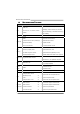
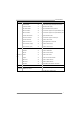
Motherboard Manual 1.3 MOTHERBOARD FEATURES SPEC Supports Execute Disable Bit / Enhanced Intel Socket 1155 CPU SpeedStep® / Intel Architecture-64 / Extended Intel Core i7 / i5 / i3 / Pentium / Celeron Memory 64 Technology / Virtualization Technology / processor Hyper Threading Chipset Intel B75 IT8728 Environment Control initiatives, Provides the most commonly used legacy Hardware Monitor Controller Super I/O functionality.
B75MU3+ SPEC CPU Fan Header x1 CPU Fan power supply (with Smart Fan function) System Fan Header x1 System Fan Power supply Clear CMOS Header x1 Restore CMOS data to factory default USB2.0 Connector x2 Each connector supports 2 front panel USB2.0 ports USB3.0 Connector x1 Each connector supports 2 front panel USB3.
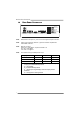
Motherboard Manual 1.4 REAR PANEL CONNECTORS PS/2 Keyboard / Mouse LAN Line In/ Surround Line Out Mic In 1/ Bass/ Center USB2.0X2 VGA HDMI DVI-D USB3.0X2 NOTE: HDMI, DVI-D & VGA ports only work with an Intel integrated Graphics Processor. NOTE: USB3.0 (only supported by Windows 7) ports are backward compatible with USB2.0/USB1.X devices. NOTE: Maximum resolution: HDMI: 1920 x 1200 @60Hz, compliant with HDMI 1.
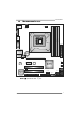
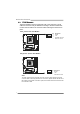
B75MU3+ 1.5 MOTHERBOARD LAYOUT USB_KBMS1 C PU _FA N1 VGA1 DDR3_B1 DD R3_B2 C PU1 DDR3_A2 DDR3_A1 HD MI1 Socket 1155 DVI1 ATXP W R1 R J45U SB1 BAT1 AUDIO1 JS PDI FO UT1 F_AUDIO1 PE X16_1 BIOS P E X1_1 LAN CODEC B75 JC MOS 1 SATA 1 SATA 2 PCI1 CI R1 Super I/O PCI2 J_COM1 J_PRINT1 F_U SB 1 S YS _FA N1 JFRONT_USB3_1 F_U SB 2 S ATA 5 PAN EL1 S ATA 6 SATA 3 SATA 4 Note: ■ represents the 1st pin.
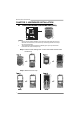
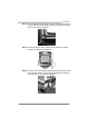
Motherboard Manual CHAPTER 2: HARDWARE INSTALLATION 2.1 INSTALLING CENTRAL PROCESSING UNIT (CPU) Notice: 1. 2. Remove Pin Cap before installation, and make good preservation for future use. When the CPU is removed, cover the Pin Cap on the empty socket to ensure pin legs won’t be damaged. The motherboard might equip with two different types of pin cap. Please refer below instruction to remove the pin cap. Step 1: Pull the socket locking lever out from the socket and then raise the lever up.
B75MU3+ Step 3: Look for the triangular cut edge on socket, and the golden dot on CPU should point forwards this triangular cut edge. The CPU will fit only in the correct orientation. Step 4: Hold the CPU down firmly, and then lower the lever to locked position to complete the installation. Step 5: Put the CPU Fan and heatsink assembly on the CPU and buckle it on the retention frame. Connect the CPU FAN power cable into the CPU_FAN1 to complete the installation.
Motherboard Manual 2.2 FAN HEADERS These fan headers support cooling-fans built in the computer. The fan cable and connector may be different according to the fan manufacturer. Connect the fan cable to the connector while matching the black wire to pin#1.
B75MU3+ 2.3 INSTALLING SYSTEM MEMORY DDR3_B1 DDR3_B2 DDR3_A1 DDR3_A2 A. Memory Modules 1. Unlock a DIMM slot by pressing the retaining clips outward. Align a DIMM on the slot such that the notch on the DIMM matches the break on the Slot. 2. Insert the DIMM vertically and firmly into the slot until the retaining chip snap back in place and the DIMM is properly seated.
Motherboard Manual B. Memory Capacity DIMM Socket Location DDR3 Module DDR3_A1 512MB/1GB/2GB/4GB/8GB DDR3_A2 512MB/1GB/2GB/4GB/8GB DDR3_B1 512MB/1GB/2GB/4GB/8GB DDR3_B2 512MB/1GB/2GB/4GB/8GB Total Memory Size Max is 32GB. C. Dual Channel Memory Installation Please refer to the following requirements to activate Dual Channel function: Install memory module of the same density in pairs, shown in the table.
B75MU3+ 2.4 CONNECTORS AND SLOTS SATA1: Serial ATA3.0 Connectors The motherboard has a PCI to SATA Controller with 1 channels SATA interface, it satisfies the SATA 3.0 spec and with transfer rate of 6.0Gb/s. 1 4 7 Pin 1 2 3 4 5 6 7 Assignment Ground TX+ TXGround RXRX+ Ground SATA2 ~ 6: Serial ATA2.0 Connectors The motherboard has a PCI to SATA Controller with 5 channels SATA2 interface, it satisfies the SATA 2.0 spec and with transfer rate of 3.0Gb/s.
Motherboard Manual PEX16_1: PCI-Express Gen3 x16 Slot - PCI-Express 3.0 compliant. Maximum theoretical realized bandwidth of 16GB/s simultaneously per direction, for an aggregate of 32GB/s totally. PCI-Express Gen3 supports a raw bit-rate of 8.0Gb/s on the data pins. PCI-E 3.0 is supported by Core i7-3xxx / i5-3xxx CPU. PEX1_1: PCI-Express Gen2 x1 Slot - PCI-Express 2.0 compliant. Data transfer bandwidth up to 500MB/s per direction; 1GB/s in total. PCI-Express supports a raw bit-rate of 2.
B75MU3+ ATXPWR1: ATX Power Source Connector This connector allows user to connect 24-pin power connector on the ATX power supply. Pin 13 14 15 16 17 18 19 20 21 22 23 24 Assignment +3.3V -12V Ground PS_ON Ground Ground Ground NC +5V +5V +5V Ground Pin 1 2 3 4 5 6 7 8 9 10 11 12 12 24 1 13 Assignment +3.3V +3.3V Ground +5V Ground +5V Ground PW_OK Standby Voltage+5V +12V +12V +3.3V ATXPWR2: ATX Power Source Connector This connector provides +12V to CPU power circuit.
Motherboard Manual CHAPTER 3: HEADERS & JUMPERS SETUP 3.1 HOW TO SETUP JUMPERS The illustration shows how to set up jumpers. When the jumper cap is placed on pins, the jumper is “close”, if not, that means the jumper is “open”. Pin opened 3.2 Pin closed Pin1-2 closed DETAIL SETTINGS PANEL1: Front Panel Header This 16-pin connector includes Power-on, Reset, HDD LED, Power LED, and speaker connection. It allows user to connect the PC case’s front panel switch functions.
B75MU3+ F_USB1/F_USB2: Headers for USB 2.0 Ports at Front Panel These headers allow user to connect additional USB cable on the PC front panel, and also can be connected with internal USB devices, like USB card reader. Pin 1 2 3 4 5 6 7 8 9 10 F_USB 1 F_USB 2 2 10 1 9 Assignment +5V (fused) +5V (fused) USBUSBUSB+ USB+ Ground Ground Key NC JFRONT_USB3_1: Header for USB 3.
Motherboard Manual F_AUDIO1: Front Panel Audio Header This header allows user to connect the front audio output cable with the PC front panel. This header supports HD and AC’97 audio front panel connector. 10 9 2 1 Pin 1 2 3 4 5 6 7 8 9 10 Assignment Mic Left in Ground Mic Right in GPIO Right line in Jack Sense Front Sense Key Left line in Jack Sense JSPDIFOUT1: Digital Audio-out Connector This connector allows user to connect the PCI bracket SPDIF output header.
B75MU3+ JCMOS1: Clear CMOS Header Placing the jumper on pin2-3 allows user to restore the BIOS safe setting and the CMOS data. Please carefully follow the procedures to avoid damaging the motherboard. 1 3 Pin 1-2 Close: Normal Operation (default). 1 1 3 Pin 2-3 Close: Clear CMOS data. 3 ※ Clear CMOS Procedures: 1. 2. 3. 4. 5. 6. Remove AC power line. Set the jumper to “Pin 2-3 close”. Wait for five seconds. Set the jumper to “Pin 1-2 close”. Power on the AC.
Motherboard Manual J_PRINT1: Printer Port Connector This header allows you to connector printer on the PC.
B75MU3+ CHAPTER 4: USEFUL HELP 4.1 DRIVER INSTALLATION NOTE After you installed your operating system, please insert the Fully Setup Driver CD into your optical drive and install the driver for better system performance. You will see the following window after you insert the CD The setup guide will auto detect your motherboard and operating system. Note: If this window didn’t show up after you insert the Driver CD, please use file browser to locate and execute the file SETUP.
Motherboard Manual 4.2 SOFTWARE Installing Software 1. Insert the Setup CD to the optical drive. The drivers installation program would appear if the Autorun function has been enabled. 2. Select Software Installation, and then click on the respective software title. 3. Follow the on-screen instructions to complete the installation. Launching Software After the installation process, you will see the software icon “eHOT Line” / “BIOS Update” appears on the desktop.
B75MU3+ After filling up this information, click “Send” to send the mail out. A warning dialog would appear asking for your confirmation; click “Send” to confirm or “Do Not Send” to cancel. If you want to save this information to a .txt file, click “Save As…” and then you will see a saving dialog appears asking you to enter file name. Enter the file name and then click “Save”. Your system information will be saved to a .txt file. Open the saved .
Motherboard Manual BIOS Update BIOS Update is a convenient utility which allows you to update your motherboard BIOS under Windows system. AWARD BIOS Show current BIOS information Clear CMOS function (Only for AWARD BIOS) Save current BIOS to a .bin file Update BIOS with a BIOS file Once click on this button, the saving dialog will show. Choose the position to save file and enter file name. (We recommend that the file name should be English/number and no longer than 7 characters.
B75MU3+ Before doing this, please download the proper BIOS file from the website. For AWARD BIOS, update BIOS procedure should be run with Clear CMOS function, so please check on Clear CMOS first. Then click Update BIOS button, a dialog will show for asking you backup current BIOS. Click Yes for BIOS backup and refer to the Backup BIOS procedure; or click No to skip this procedure.
Motherboard Manual Intel® Small Business Advantage Intel Small Business Advantage (Intel SBA) provides an out-of-the-box hardware-based security and productivity suite designed for the small business user. Supported Operating Systems: z z Windows 7 Professional 64-bit and 32-bit Windows 7 Enterprise 64-bit Installing Intel SBA This procedure describes how to install Intel SBA. 1. Logon to the computer with a user that has administrator privileges. 2. Copy the Setup.exe file to the computer. 3.
B75MU3+ 4. Click Next. The installer starts the installation and the Setup Progress window opens showing the progress of the installation. When installation is complete, the installer starts the Intel SBA service and the Next button is enabled. 5. Click Next. The Setup Is Complete window opens. 6. Click Finish. The installer closes.
Motherboard Manual 4.3 EXTRA INFORMATION CPU Overheated If the system shuts down automatically after system is powered on for seconds, the phenomenon means the CPU protection function has been activated. When the CPU is over heated, the motherboard will shutdown automatically to avoid a damage of the CPU, and the system may not power on again. In this case, please double check: 1. The CPU cooler surface is placed evenly with the CPU surface. 2. CPU fan is rotated normally. 3.
B75MU3+ 4.4 AMI BIOS BEEP CODE Boot Block Beep Codes Number of Beeps 1 2 3 4 5 7 10 11 12 13 Description No media present. (Insert diskette in floppy drive A:) “AMIBOOT.ROM” file not found in root directory of diskette in A: Insert next diskette if multiple diskettes are used for recovery Flash Programming successful File read error No Flash EPROM detected Flash Erase error Flash Program error “AMIBOOT.
Motherboard Manual 4.5 TROUBLESHOOTING Probable 1. There is no power in the system. Power LED does not shine; the fan of the power supply does not work 2. Indicator light on keyboard does not shine. System is inoperative. Keyboard lights are on, power indicator lights are lit, and hard drives are running. System does not boot from a hard disk drive, but can be booted from optical drive. Solution 1. 2. 3. Make sure power cable is securely plugged in. Replace cable. Contact technical support.
B75MU3+ This page is intentionally left blank.
Motherboard Manual APPENDIX: SPEC IN OTHER LANGUAGES GERMAN Spezifikationen Unterstützt Execute Disable Bit / Enhanced Intel Socket 1155 CPU Intel Core i7 / i5 / i3 / Pentium / Celeron Prozessoren Chipsatz Intel B75 Umgebungskontrolle, Bietet die häufig verwendeten alten Super Hardware-Überwachung E/A-Funktionen.
B75MU3+ Spezifikationen CPU-Lüfter-Sockel x1 System-Lüfter-Sockel x1 "CMOS löschen"-Sockel x1 USB2.0-Anschluss x2 CPU-Lüfterstromversorgungsanschluss (mit Smart Fan-Funktion) System-Lüfter-Stromversorgungsanschluss Jeder Anschluss unterstützt 2 Fronttafel-USB2.0-Anschlüsse USB3.0-Anschluss x1 Jeder Anschluss unterstützt 2 Fronttafel-USB3.
Motherboard Manual FRENCH SPEC Prend en charge les technologies d'exécution de bit Socket 1155 UC Processeurs Intel Core i7 / i5 / i3 / Pentium / Celeron Chipset Super E/S Intel B75 IT8728 Initiatives de contrôle environnementales, Fournit la fonctionnalité de Super E/S Moniteur de matériel patrimoniales la plus utilisée.
B75MU3+ SPEC Connecteur Audio du panneau avant x1 Embase de ventilateur UC x1 Embase de ventilateur système x1 Embase d'effacement CMOS x1 Connecteur USB2.0 x2 Connecteur USB3.0 x1 Prend en charge la fonction audio du panneau avant Alimentation électrique du ventilateur UC (avec fonction de ventilateur intelligent) Alimentation électrique du ventilateur système Chaque connecteur prend en charge 2 ports USB2.0 de panneau avant Chaque connecteur prend en charge 2 ports USB3.
Motherboard Manual ITALIAN SPECIFICA Supporto di Execute Disable Bit / Enhanced Socket 1155 CPU Processore Intel Core i7 / i5 / i3 / Pentium / Celeron Chipset Tecnologia Extended Memory 64 / Tecnologia Virtualization / Hyper Threading Intel B75 IT8728 Super I/O Intel SpeedStep® / Architettura Intel 64 / Funzioni di controllo dell’ambiente: Fornisce le funzionalità legacy Super I/O Monitoraggio hardware usate più comunemente.
B75MU3+ SPECIFICA Collettore ventolina CPU x1 Collettore ventolina sistema x1 Collettore cancellaz ione CMOS x1 Connettore USB2.0 x2 Connettore USB3.0 x1 Alimentazione ventolina CPU (con funzione Smart Fan) Alimentazione ventolina di sistema Ciascun connettore supporta 2 porte USB2.0 pannello frontale Ciascun connettore supporta 2 porte USB3.
Motherboard Manual SPANISH Especificación Admite Bit de deshabilitación de ejecución / Intel Socket 1155 CPU Procesador Intel Core i7 / i5 / i3 / Pentium / Celeron Conjunto de chips Súper E/S Intel B75 IT8728 Iniciativas de control de entorno, Le ofrece las funcionalidades heredadas de Monitor hardware uso más común Súper E/S.
B75MU3+ Especificación Cabecera de ventilador de CPU X1 Fuente de alimentación de ventilador de CPU (con función Smart Fan) Cabecera de ventilador de sistema X1 Fuente de alimentación de ventilador de sistema Cabecera de borrado de CMOS X1 Conector USB2.0 X2 Cada conector soporta 2 puertos USB2.0 frontales Conector USB3.0 X1 Cada conector soporta 2 puertos USB3.
Motherboard Manual PORTUGUESE ESPECIFICAÇÕES Suporta as tecnologias Execute Disable Bit / Socket 1155 CPU Processador Intel Core i7 / i5 / i3 / Pentium / Celeron Chipset o Super I/O / Extended Memory 64 / Virtualization / Hyper Threading Intel B75 IT8728 Especificaçã Enhanced Intel SpeedStep® / Intel Arquitecture -64 Iniciativas para controlo do ambiente Proporciona as funcionalidades mais utilizadas em termos da especificação Super I/O.
B75MU3+ ESPECIFICAÇÕES Conector de áudio frontal x1 Conector da ventoinha da CPU x1 Conector da ventoinha do sistema x1 Conector para limpeza do CMOS x1 Conector USB2.0 x2 Conector USB3.
Motherboard Manual POLISH SPEC Obsługa Execute Disable Bit / Enhanced Intel Socket 1155 Procesor Procesor Intel Core i7 / i5 / i3 / Pentium / Celeron Chipset SpeedStep® / Intel Architecture-64 / Extended Memory 64 Technology / Virtualization Technology / Hyper Threading Intel B75 Gniazda DDR3 DIMM x 4 Moduł pamięci DDR3 z trybem podwójnego kanału Pamięć Maks.
B75MU3+ SPEC Złącze główkowe wentylatora systemowego x1 Zasilanie wentylatora systemowego Złącze główkowe kasowania CMOS x1 Złącze USB2.0 x2 Złącze USB3.0 x1 Złącze Konsument IR x1 Złącze Port drukarki x1 Port szeregowy x1 Złącze wyjścia S/PDIF x1 Złącze zasilania (24 pinowe) x1 Złącze zasilania (4 pinowe) x1 Klawiatura PS/2 x1 Port HDMI x1 Port VGA x1 Back Panel Port DVI x1 I/O Port LAN x1 Port USB2.0 x2 Port USB3.
Motherboard Manual RUSSIAN СПЕЦ CPU (центральн ый Поддержка технологий Execute Disable Bit / Socket 1155 Процессор Intel Core i7 / i5 / i3 / Pentium / Celeron / Extended Memory 64 Technology / технологии виртуализация / Hyper Threading процессор) Набор Enhanced Intel SpeedStep® / Intel Architecture-64 Intel B75 микросхем Модуль памяти с двухканальным режимом DDR3 Слоты DDR3 DIMM x 4 Основная Максимальная ёмкость памяти 32 ГБ память Каждый модуль DIMM поддерживает 512МБ/1ГБ/2ГБ/4ГБ/8 ГБ DDR3 Sup
B75MU3+ СПЕЦ Источник питания для вентилятора центрального Контактирующее приспособление вентилятора центрального процессора x1 Контактирующее приспособление вентилятора системы x1 процессора (с функцией интеллектуального вентилятора) Источник питания для вентилятора системы Открытое контактирующее приспособление CMOS x1 USB2.0-разъём x2 USB3.
Motherboard Manual ARABIC اﻟﻤﻮاﺻﻔﺎت Execute Disable Bit / Enhanced Intelﺗﺪﻋﻢ ﺗﻘﻨﻴﺎت Socket 1155 وﺣﺪة اﻟﻤﻌﺎﻟﺠﺔ اﻟﻤﺮآﺰیﺔ Intel Core i7 / i5 / i3 / Pentium /ﻣﻌﺎﻟﺠﺎت ﺑﺘﺮدد یﺼﻞ إﻟﻰ Celeron SpeedStep® / Intel Architecture-64 / Extended Memory 64 Technology / Virtualization Technology / Hyper Threading ﻣﺠﻤﻮﻋﺔ اﻟﺸﺮاﺋﺢ Intel B75 ﻣﺰدوﺝﺔ اﻟﻘﻨﺎةDDR3وﺣﺪة ذاآﺮة ﺳﻌﺎت 1333 / 1066ﻣﻴﺠﺎ ﺑﺎیﺖDDR3ﺗﺪﻋﻢ اﻟﺬاآﺮة ﻣﻦ ﻥﻮع اﻟﺬاآﺮة اﻟﺮﺋﻴﺴﻴﺔ 1600(Dependingﺳ ﻌﺎت DDR3ﻧ ﻮ
B75MU3+ اﻟﻤﻮاﺻﻔﺎت وﺹﻠﺔ ﻣﺮوﺣﺔ اﻟﻨﻈﺎم ﻋﺪد 1 وﺹﻠﺔ ﻣﺴﺢ CMOS ﻋﺪد 1 ﻣﻨﻔﺬ USB2.0 ﻋﺪد 2 یﺪﻋﻢ آﻞ ﻣﻨﻔﺬ ﻓﺘﺤﺘﻲ USB2.0ﺑﺎﻟﻠﻮﺣﺔ اﻷﻣﺎﻣﻴﺔ ﻣﻨﻔﺬ USB3.0 ﻋﺪد 1 یﺪﻋﻢ آﻞ ﻣﻨﻔﺬ ﻓﺘﺤﺘﻲ USB3.
Motherboard Manual JAPANESE 仕様 Execute Disable Bit / Enhanced Intel SpeedStep® / Socket 1155 CPU Intel Core i7 / i5 / i3 / Pentium / Celeron プロ セッサ Intel Architecture-64 / Extended Memory 64 Technology / Virtualization Technology / Hyper Threadingをサポートします チップセット Intel B75 DDR3 DIMMスロット x 4 デュアル チャンネルモードDDR3メモリモジュール 最大メモリ容量32GB DDR3 1066 / 1333 をサポート メインメモリ 各DIMMは 512MB/1GB/2GB/4GB/8GB DDR3 DDR3 1600(Depending on CPU) をサポート Super I/O をサポート 登録済みDIMMとECC DIMMはサポートされません IT8728 環境コントロールイニシアチブ、 もっと
B75MU3+ 仕様 CMOSクリアヘッダ x1 USB2.0コネクタ x2 各コネクタは2つのフロントパネルUSB2.0ポートをサポ ートします USB3.0コネクタ x1 各コネクタは2つのフロントパネルUSB3.0ポートをサポ ートします 消費者IRコネクタ x1 プリンタポートコネクタ x1 シリアルポート x1 S/PDIFアウトコネクタ x1 電源コネクタ(24ピン) x1 電源コネクタ(4ピン) x1 PS/2キーボード x1 HDMIポート x1 VGAポート x1 背面パネル DVI-Dポート x1 I/O LANポート x1 USB2.0ポート x2 USB3.