G41-M7 Setup Manual FCC Information and Copyright This equipment has been tested and found to comply with the limits of a Class B digital device, pursuant to Part 15 of the FCC Rules. These limits are designed to provide reasonable protection against harmful interference in a residential installation. This equipment generates, uses, and can radiate radio frequency energy and, if not installed and used in accordance with the instructions, may cause harmful interference to radio communications.
Table of Contents Chapter 1: Introduction.......................................... 1 1.1 1.2 1.3 1.4 1.5 Before You Start ................................................................................1 Package Checklist ............................................................................1 Motherboard Specifications .............................................................2 Rear Panel Connectors....................................................................3 Motherboard Layout...........
G41-M7 CHAPTER 1: INTRODUCTION 1.1 Before You Start Thank you for choosing our product. Before you start installing the motherboard, please make sure you follow the instructions below: Prepare a dry and stable working environment with sufficient lighting. Always disconnect the computer from power outlet before operation.
Motherboard Manual 1.
G41-M7 SPEC SATA Connector x4 Each connector supports 1 SATA devices Front Panel Connector x1 Supports front panel facilities Front Audio Connector x1 Supports front panel audio function CPU Fan Header x1 CPU Fan power supply (with Smart Fan function) System Fan Header x1 System Fan Power supply Clear CMOS Header x1 Restore CMOS data to factory default USB 2.
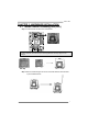
Motherboard Manual 1.5 Motherboard Layout Note: ■ represents the 1st pin.
G41-M7 CHAPTER 2: HARDWARE INSTALLATION 2.1 Install Central Processing Unit (CPU) Step 1: Locate the CPU socket on the motherboard Note: Remove Pin Cap before installation, and make good preservation for future use. When the CPU is removed, cover the Pin Cap on the empty socket to ensure pin legs won’t be damaged. Pin-Cap Step 2: Pull the socket locking lever out from the socket and then raise the lever up to a 90-degree angle.
Motherboard Manual Step 3: Look for the triangular cut edge on socket, and the golden dot on CPU should point forwards this triangular cut edge. Step 3-1: Step 3-2: Step 4: Hold the CPU down firmly, and then lower the lever to locked position to complete the installation. Note: The CPU fits only in one correct orientation. Do not force the CPU into the socket to prevent damaging the CPU.
G41-M7 2.2 Install a Heatsink Step 1: Place the CPU fan assembly on top of the installed CPU and make sure that the four fasteners match the motherboard holes. Orient the assembly and make the fan cable is closest to the CPU fan connector. Step 2: Press down two fasteners at one time in a diagonal sequence to secure the CPU fan assembly in place. Ensure that all four fasteners are secured. Note1: Do not forget to connect the CPU fan connector.
Motherboard Manual 2.3 Connect Cooling Fans These fan headers support cooling-fans built in the computer. The fan cable and connector may be different due to the fan manufacturer. Connect the fan cable to the connector while matching the black wire to pin#1.
G41-M7 2.4 Install System Memory A. DDR2 module Step 1: Unlock a DIMM slot by pressing the retaining clips outward. Align a DIMM on the slot such that the notch on the DIMM matches the break on the slot. Step 2: Insert the DIMM vertically and firmly into the slot until the retaining chip snap back in place and the DIMM is properly seated. Note: If the DIMM does not go in smoothly, do not force it. Pull it all the way out and try again.
Motherboard Manual B. Memory Capacity DIMM Socket Location DDR2 Module Total Memory Size DDR2_A1 256MB/512MB/1GB/2GB/4GB DDR2_B1 256MB/512MB/1GB/2GB/4GB Max is 8GB. C. Dual Channel Memory Installation Please refer to the following requirements to activate Dual Channel function: Install memory module of the same density in pairs, shown in the table. Dual Channel Status DDR2_A1 Disabled O X Disabled X O Enabled O O DDR2_B1 (O means memory installed; X, not installed.
G41-M7 2.5 Expansion Slots PEX16_1: PCI-Express x16 Slot - PCI-Express 1.0a compliant. Maximum theoretical realized bandwidth of 4GB/s simultaneously per direction, for an aggregate of 8GB/s totally. PCI-Express supports a raw bit-rate of 2.5Gb/s on the data pins. 2X bandwidth over the traditional PCI architecture. PCI1/PCI2: Peripheral Component Interconnect Slots This motherboard is equipped with 2 standard PCI slots.
Motherboard Manual Install an Expansion Card You can install your expansion card by following steps: 1. Read the related expansion card's instruction document before install the expansion card into the computer. 2. Remove your computer's chassis cover, screws and slot bracket from the computer. 3. Place a card in the expansion slot and press down on the card until it is completely seated in the slot. 4. Secure the card’s metal bracket to the chassis back panel with a screw. 5.
G41-M7 2.6 Jumper Setting The illustration shows how to set up jumpers. When the jumper cap is placed on pins, the jumper is “close”, if not, that means the jumper is “open”. Pin opened Pin closed Pin1-2 closed JCMOS1: Clear CMOS Header Placing the jumper on pin2-3 allows user to restore the BIOS safe setting and the CMOS data. Please carefully follow the procedures to avoid damaging the motherboard. 3 1 Pin 1-2 Close: Normal Operation (Default). 3 1 Pin 2-3 Close: Clear CMOS data.
Motherboard Manual 2.7 Herders & Connectors ATXPWR1: ATX Power Source Connector By connecting this connector, it will provide +12V to CPU power circuit. Pin 1 2 3 4 Assignment +12V +12V Ground Ground ATXPWR2: ATX Power Source Connector This connector allows user to connect 24-pin power connector on the ATX power supply. Pin 13 14 15 16 17 18 19 20 21 22 23 24 Assignment +3.3V -12V Ground PS_ON Ground Ground Ground NC +5V +5V +5V Ground Pin 1 2 3 4 5 6 7 8 9 10 11 12 Assignment +3.3V +3.
G41-M7 PANEL1: Front Panel Header This 16-pin connector includes Power-on, Reset, HDD LED, Power LED, and speaker connection. It allows user to connect the PC case’s front panel switch functions.
Motherboard Manual F_USB1/F_USB2: Headers for USB 2.0 Ports at Front Panel This motherboard provides 2 USB 2.0 headers, which allows user to connect additional USB cable on the PC front panel, and also can be connected with internal USB devices, like USB card reader.
G41-M7 SATA1~SATA4: Serial ATA Connectors The motherboard has a PCI to SATA Controller with 4channels SATA interface, it satisfies the SATA 2.0 spec and with transfer rate of 3Gb/s. Pin 1 2 3 4 5 6 7 Assignment Ground TX+ TXGround RXRX+ Ground JCOM1: Serial port Connector The motherboard has a Serial Port Connector for connecting RS-232 Port.
Motherboard Manual JPRNT1: Printer Port Connector This header allows you to connector printer on the PC.
G41-M7 CHAPTER 3: BIOS & SOFTWARE 3.1 3.2 BIOS Setup For better system performance, the BIOS firmware is being continuously updated. The BIOS information described below in this manual is for your reference only and the actual BIOS information and settings on board may be different from this manual For further information of setting up the BIOS, please refer to the BIOS Manual in the Setup DVD.
Motherboard Manual Once click on this button, the saving dialog will show. Choose the position to save file and enter file name. (We recommend that the file name should be English/number and no longer than 7 characters.) Then click Save. After the saving process, finish dialog will show. Click on OK to complete the BIOS Backup procedure. Before doing this, please download the proper BIOS file from the website.
G41-M7 The utility will update BIOS with the proper BIOS file, and this process may take minutes. Please do not open any other applications during this process. After the BIOS Update process, click on OK to restart the system. While the system boots up and the full screen logo shows, press key to enter BIOS setup. In the BIOS setup, use the Load Optimized Defaults function and then Save and Exit Setup to exit BIOS setup. BIOS Update is completed. 2. Online Update Utility 1.
Motherboard Manual 5. If there is a new BIOS version, the utility will ask you to download it. Click Yes to proceed. 6. After the download is completed, you will be asked to program (update) the BIOS or not. Click Yes to proceed. 7. After the updating process is finished, you will be asked you to reboot the system. Click OK to reboot. 8. While the system boots up and the full screen logo shows up, press key to enter BIOS setup.
G41-M7 3. BIOSTAR BIOS Flasher BIOSTAR BIOS Flasher is a BIOS flashing utility providing you an easy and simple way to update your BIOS via USB pen drive. Note1: This utility only allows storage device with FAT32/16 format and single partition. Note2: Shutting down or resetting the system while updating the BIOS will lead to system boot failure. The BIOSTAR BIOS Flasher is built in the BIOS ROM. To enter the utility, press during the Power-On Self Tests (POST) procedure while booting up.
Motherboard Manual 3.3 Software Installing Software 1. Insert the Setup DVD to the optical drive. The driver installation program would appear if the Autorun function has been enabled. 2. Select Software Installation, and then click on the respective software title. 3. Follow the on-screen instructions to complete the installation. Note1: All the information and content about following software are subject to be changed without notice. For better performance, the software is being continuously updated.
G41-M7 After filling up this information, click “Send” to send the mail out. A warning dialog would appear asking for your confirmation; click “Send” to confirm or “Do Not Send” to cancel. If you want to save this information to a .txt file, click “Save As…” and then you will see a saving dialog appears asking you to enter file name. Enter the file name and then click “Save”. Your system information will be saved to a .txt file. Open the saved .
Motherboard Manual BIOScreen Utility (Optional) This utility allows you to personalize your boot logo easily. You can choose BMP as your boot logo so as to customize your computer. Please follow the following instructions to update boot logo: 1. Load Image:Choose the picture as the boot logo. 2. Transform:Transform the picture for BIOS and preview the result. 3. Update Bios:Write the picture to BIOS Memory to complete the update.
G41-M7 CHAPTER 4: USEFUL HELP 4.1 Driver Installation After you installed your operating system, please insert the Fully Setup Driver DVD into your optical drive and install the driver for better system performance. You will see the following window after you insert the DVD The setup guide will auto detect your motherboard and operating system. Note: If this window didn’t show up after you insert the Driver DVD, please use file browser to locate and execute the file SETUP.EXE under your optical drive.
Motherboard Manual 4.2 Extra Information CPU Overheated If the system shutdown automatically after power on system for seconds, that means the CPU protection function has been activated. When the CPU is over heated, the motherboard will shutdown automatically to avoid a damage of the CPU, and the system may not power on again. In this case, please double check: 1. The CPU cooler surface is placed evenly with the CPU surface. 2. CPU fan is rotated normally. 3.
G41-M7 4.3 AMI BIOS Beep Code Boot Block Beep Codes Number of Beeps 1 2 3 4 5 7 10 11 12 13 Description No media present. (Insert diskette in floppy drive A:) “AMIBOOT.ROM” file not found in root directory of diskette in A: Insert next diskette if multiple diskettes are used for recovery Flash Programming successful File read error No Flash EPROM detected Flash Erase error Flash Program error “AMIBOOT.
Motherboard Manual 4.4 Troubleshooting Probable 1. 2. Solution There is no power in the system. 1. Power LED does not shine; the fan of the power supply does not 2. work 3. Indicator light on keyboard does not shine. Make sure power cable is securely plugged in. Replace cable. Contact technical support. System is inoperative. Keyboard lights Using even pressure on both ends of are on, power indicator lights are lit, the DIMM, press down firmly until the and hard drives are running.
G41-M7 This page is intentionally left blank.
Motherboard Manual APPENDIX: Specifications In Other Languages German Spezifikationen LGA 775 Unterstützt Hyper-Threading / Execute Disable Bit / Intel Core2Duo / Core2Quad / Pentium Dual-Core CPU Enhanced Intel SpeedStep® / Intel Architecture-64 / / Celeron Dual-Core / Celeron 4xx Prozessoren Extended Memory 64 Technology / Virtualization Technology (Maximales Watt: 95W) FSB 533 / 800 / 1066 / 1333 MHz, FSB533 unterstützt nur DDR2-533 Intel G41 Chipsatz Intel ICH7 ITE 8728F-BX Umgebungskontrolle, Bi
G41-M7 Spezifikationen Druckeranschluss Anschluss x1 Jeder Anschluss unterstützt 1 Druckeranschluss Serieller Anschluss x1 IDE-Anschluss x1 Jeder Anschluss unterstützt 2 IDE-Laufwerke SATA-Anschluss x4 Jeder Anschluss unterstützt 1 SATA-Laufwerk Fronttafelanschluss x1 Unterstützt die Fronttafelfunktionen Front-Audioanschluss x1 Unterstützt die Fronttafel-Audioanschlussfunktion CPU-Lüfter-Sockel x1 Onboard-Ansc CPU-Lüfterstromversorgungsanschluss (mit Smart hluss Fan-Funktion) System-Lüft
Motherboard Manual French SPEC LGA 775 Prend en charge les technologies Hyper-Threading / Processeurs Intel Core2Duo / Core2Quad / d'exécution de bit de désactivation / Intel SpeedStep® UC Pentium Dual-Core / Celeron Dual-Core / optimisée/ d'architecture Intel 64 / de mémoire étendue 64 / de Celeron 4xx virtualisation (Watt maximum : 95W) Bus frontal 533 / 800 / 1066 / 1333 MHz, FSB533 seul soutien DDR2-533 Intel G41 Chipset Intel ICH7 ITE 8728F-BX Initiatives de contrôle environnementales, Fournit l
G41-M7 SPEC Fente PCI Express x16 x1 Connecteur de Port d'imprimante x1 Port série x1 Connecteur IDE x1 Chaque connecteur prend en charge 2 périphériques IDE Connecteur SATA x4 Chaque connecteur prend en charge 1 périphérique SATA Connecteur du panneau avant x1 Prend en charge les équipements du panneau avant Connecteur Audio du panneau avant x1 Chaque connector prend en charge 1 Port d'imprimante Prend en charge la fonction audio du panneau avant Alimentation électrique du ventilateur UC (
Motherboard Manual Italian SPECIFICA LGA 775 Supporto di Hyper-Threading / Execute Disable Bit / Processore Intel Core2Duo / Core2Quad / Enhanced Intel SpeedStep® / Architettura Intel 64 / CPU Pentium Dual-Core / Celeron Dual-Core / Tecnologia Extended Memory 64 / Tecnologia Celeron 4xx Virtualization (Watt massimo: 95W) FSB 533 / 800 / 1066 / 1333 MHz, FSB533 solo supporto DDR2-533 Intel G41 Chipset Intel ICH7 ITE 8728F-BX Funzioni di controllo dell’ambiente: Fornisce le funzionalità legacy Super I/
G41-M7 SPECIFICA Connettori su scheda Connettore Porta stampante x1 Ciascun connettore supporta 1 Porta stampante Porta seriale x1 Connettore IDE x1 Ciascun connettore supporta 2 unità IDE Connettore SATA x4 Ciascun connettore supporta 1 unità SATA Connettore pannello frontale x1 Supporta i servizi del pannello frontale Connettore audio frontale x1 Supporta la funzione audio pannello frontale Collettore ventolina CPU x1 Alimentazione ventolina CPU (con funzione Smart Fan) Collettore ve
Motherboard Manual Spanish Especificación LGA 775 CPU Procesador Intel Core2Duo / Core2Quad / Admite Hyper-Threading / Bit de deshabilitación de ejecución / Pentium Dual-Core / Celeron Dual-Core / Intel SpeedStep® Mejorado / Intel Architecture-64 / Tecnología Celeron 4xx Extended Memory 64 / Tecnología de virtualización (Vatio máximo: 95W) FSB 533 / 800 / 1066 / 1333 MHz, FSB533 único soporte DDR2-533 Conjunto de Intel G41 chips Intel ICH7 Iniciativas de control de entorno, ITE 8728F-BX Le o
G41-M7 Especificación en placa Puerto serie X1 Conector IDE X1 Cada conector soporta 2 dispositivos IDE Conector SATA X4 Cada conector soporta 1 dispositivos SATA Conector de panel frontal X1 Soporta instalaciones en el panel frontal Conector de sonido frontal X1 Soporta funciones de sonido en el panel frontal Cabecera de ventilador de CPU X1 Fuente de alimentación de ventilador de CPU (con función Smart Fan) Cabecera de ventilador de sistema X1 Cabecera de borrado de CMOS X1 Conector
Motherboard Manual Portuguese ESPECIFICAÇÕES LGA 775 Suporta as tecnologias Hyper-Threading / Execute Disable Bit / Processador Intel Core2Duo / Core2Quad / CPU Enhanced Intel SpeedStep® / Intel Arquitecture -64 / Extended Pentium Dual-Core / Celeron Dual-Core / Memory 64 / Virtualization Celeron 4xx (Watt máximo: 95W) FSB 533 / 800 / 1066 / 1333 MHz, FSB533 apoio apenas DDR2-533 Chipset Intel G41 + Intel ICH7 ITE 8728F-BX Iniciativas para controlo do ambiente Especificação Proporciona as funcionali
G41-M7 ESPECIFICAÇÕES Porta série x1 Conectores Conector IDE x1 Cada conector suporta 2 dispositivos IDE na placa Conector SATA x4 Cada conector suporta 1 dispositivo SATA Conector do painel frontal x1 Para suporte de várias funções no painel frontal Conector de áudio frontal x1 Suporta a função de áudio no painel frontal Conector da ventoinha da CPU x1 Alimentação da ventoinha da CPU (com a função Smart Fan) Conector da ventoinha do sistema x1 Alimentação da ventoinha do sistema Conec
Motherboard Manual Polish SPEC LGA 775 Procesor Procesor Intel Core2Duo / Core2Quad / Obsługa Hyper-Threading / Execute Disable Bit / Enhanced Pentium Dual-Core / Celeron Dual-Core / Intel SpeedStep® / Intel Architecture-64 / Extended Memory 64 Celeron 4xx Technology / Virtualization Technology (Maksymalny Watt: 95W) FSB 533 / 800 / 1066 / 1333 MHz, FSB 533 obsługują tylko DDR2-533 Intel G41 Chipset Intel ICH7 Moduł pamięci DDR2 z trybem podwójnego kanału Gniazda DDR2 DIMM x 2 Pamięć Każde gnia
G41-M7 SPEC Złącza Port szeregowy wbudowane Złącze IDE x1 x1 Każde złącze obsługuje 2 urządzenia IDE Złącze SATA x4 Każde złącze obsługuje 1 urządzenie SATA Złącze panela przedniego x1 Obsługa elementów panela przedniego Przednie złącze audio x1 Obsługa funkcji audio na panelu przednim Złącze główkowe wentylatora Zasilanie wentylatora procesora (z funkcją Smart Fan) procesora x1 Złącze główkowe wentylatora Zasilanie wentylatora systemowego systemowego x1 Złącze główkowe kasowania CMOS x1
Motherboard Manual Russian СПЕЦ CPU (центральны й процессор) LGA 775 Поддержка технологий Hyper-Threading / Execute Disable Процессор Intel Core2Duo / Core2Quad Bit / Enhanced Intel SpeedStep® / Intel Architecture-64 / Pentium Dual-Core / Celeron Dual-Core / Extended Memory 64 Technology / технологии Celeron 4xx (Максимальный ватт: 95W) виртуализация FSB 533 / 800 / 1066 / 1333 МГц , FSB533 поддерживают только DDR2-533 Набор Intel G41 микросхем Intel ICH7 Модуль памяти с двухканальным режимом
G41-M7 СПЕЦ Каждый разъём поддерживает 2 встроенных интерфейса Разъём IDE x1 Разъём SATA x4 Каждый разъём поддерживает 1 устройство SATA Разъём на лицевой панели x1 Поддержка устройств на лицевой панели Входной звуковой разъём x1 Поддержка звуковых функций на лицевой панели накопителей Контактирующее приспособление Источник питания для вентилятора центрального вентилятора центрального процессора x1 процессора (с функцией интеллектуального вентилятора) Контактирующее приспособление вентилято
Motherboard Manual Arabic اﻟﻤﻮاﺻﻔﺎت LGA 775 ﻡﻌﺎﻟﺠﺎت Intel Core2Duo / Core2Quad / Pentium ﺗﺪﻋﻢ ﺗﻘﻨﻴﺎت Hyper-Threading / Execute Disable Bit / Enhanced وﺣﺪة اﻟﻤﻌﺎﻟﺠﺔ Dual-Core / Celeron Dual-Core / Celeron 4xxﺑﺘﺮدد Intel SpeedStep® / Intel Architecture-64 / Extended Memory اﻟﻤﺮآﺰیﺔ 64 Technology / Virtualization Technology یﺼﻞ إﻟﻰ (واط ﻗﺼﻮى: 95و) اﻟﻨﺎﻗﻞ اﻷﻡﺎﻡﻲ اﻟﺠﺎﻥﺒﻲ ﺗﺮدد 533 / 800 / 1066 / 1333ﻡﻴﺠﺎ هﺮﺗﺰ FSB533 ,اﻟﺪﻋﻢ ﻓﻘﻂ DDR2-533 Intel G41 ﻡﺠﻤﻮﻋﺔ
G41-M7 اﻟﻤﻮاﺻﻔﺎت اﻟﻠﻮﺣﺔ ﻡﻨﻔﺬ ﺗﺴﻠﺴﻠﻲ ﻋﺪد1 ﻡﻨﻔﺬ IDE ﻋﺪد 1 یﺪﻋﻢ آﻞ ﻡﻨﻔﺬ اﺙﻨﻴﻦ ﻡﻦ أﺝﻬﺰة IDE ﻡﻨﻔﺬ SATA ﻋﺪد 4 یﺪﻋﻢ آﻞ ﻡﻨﻔﺬ واﺣﺪ ﻡﻦ أﺝﻬﺰة SATA ﻡﻨﻔﺬ اﻟﻠﻮﺣﺔ اﻷﻡﺎﻡﻴﺔ ﻋﺪد 1 یﺪﻋﻢ ﺗﺠﻬﻴﺰات اﻟﻠﻮﺣﺔ اﻷﻡﺎﻡﻴﺔ ﻡﻨﻔﺬ اﻟﺼﻮت اﻷﻡﺎﻡﻲ ﻋﺪد 1 یﺪﻋﻢ وﻇﻴﻔﺔ اﻟﺼﻮت ﺑﺎﻟﻠﻮﺣﺔ اﻷﻡﺎﻡﻴﺔ وﺻﻠﺔ ﻡﺮوﺣﺔ وﺣﺪة اﻟﻤﻌﺎﻟﺠﺔ اﻟﻤﺮآﺰیﺔ ﻋﺪد 1 ﻟﺘﻮﺻﻴﻞ اﻟﻄﺎﻗﺔ ﻟﻤﺮوﺣﺔ وﺣﺪة اﻟﻤﻌﺎﻟﺠﺔ ﻡﻊ وﻇﻴﻔﺔ Smart Fan وﺻﻠﺔ ﻡﺮوﺣﺔ اﻟﻨﻈﺎم ﻋﺪد 1 ﻟﺘﻮﺻﻴﻞ اﻟﻄﺎﻗﺔ ﻟﻤﺮوﺣﺔ اﻟﻨﻈﺎم وﺻﻠﺔ ﻡﺴﺢ CMOS ﻋﺪد 1
Motherboard Manual Japanese 仕様 LGA 775 CPU Intel Core2Duo / Core2Quad / Hyper-Threading / Execute Disable Bit / Enhanced Intel Pentium Dual-Core / Celeron Dual-Core / SpeedStep® / Intel Architecture-64 / Extended Memory 64 Celeron 4xx processor Technology / Virtualization Technologyをサポートします (最高のワット: 95W) FSB 533 / 800 / 1066 / 1333 MHz, FSB533のみをサポートDDR2-533 Intel G41 チップセット Intel ICH7 DDR2 DIMMスロット x 2 デュアル チャンネルモードDDR2メモリモジュール 各DIMMは 256MB / 512MB / 1GB / 2GB/ 4GB DDR2 533/ 800/1066(OC) をサポート
G41-M7 仕様 プリンタポートコネクタ x1 シリアルポート x1 IDEコネクタ x1 各コネクタは2つのIDEデバイスをサポートします SATAコネクタ x4 各コネクタは1つのSATAデバイスをサポートします フロントパネルコネクタ x1 フロントパネル機能をサポートします フロントオーディオコネクタ x1 フロントパネルオーディオ機能をサポートします CPUファンヘッダ x1 CPUファン電源装置(スマートファン機能を搭載) システムファンヘッダ x1 システムファン電源装置 CMOSクリアヘッダ x1 USBコネクタ x2 各コネクタは1つのプリンタポートをサポートします オンボードコ ネクタ 各コネクタは2つのフロントパネルUSBポートをサポートしま す 電源コネクタ(24ピン) x1 電源コネクタ(4ピン) x1 PS/2キーボード x1 PS/2マウス x1 背面パネル VGAポート x1 I/O LANポート x1 USBポート x4 オーディオジャック x3 ボードサイズ 182 mm (幅)