GF7100P-M7S Setup Manual FCC Information and Copyright This equipment has been tes ted and found to comply with the limits of a Class B digital devic e, purs uant to Part 15 of the FCC Rules . T hese limits are designed to provide reasonable protec tion against harmful interference in a residential installation.
Table of Contents Chapter 1: Introduction.....................................................3 1.1 Before You Start................................................................... 3 1.2 Package Checklist................................................................ 3 1.3 Motherboard Features.......................................................... 4 1.4 Rear Panel Connectors.......................................................... 5 1.5 Motherboard Layout ............................................
GF7100P-M7S CHAPTER 1: INTRODUCTION 1.1 BEFORE YOU ST ART Thank you for choosing our product. Be fore you start installing the mothe rboard, please make sure you follow the instructions be low: Prepare a dry and stable work ing environment with sufficie nt lighting. Always disconne ct the compute r from powe r outle t be fore ope ration.
Motherboard Manual 1.
GF7100P-M7S SPEC CD-in Connector x1 Supports CD audio-in function S/PDIF out connector x1 Supports digital audio out function CPU Fan header x1 CPU Fan power supply (with Smart Fan function) System Fan header x2 System Fan Power supply CMOS clear header x1 Restore CMOS data to factory default USB connector x3 Each connector supports 2 front panel USB ports Serial port Connector x1 Connects to RS-232 Port Power Connector (24pin) x1 Connects to Power supply Power Connector (4pin) x1
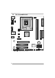
Motherboard Manual 1.5 MOT HERBOARD LAYOUT JUSBKB1 JCFAN1 LGA775 JDVI1 JUS BV1 CPU1 DIMMA2 JVGA1 DIMMA1 JATXPWR1 JNFAN1 GeForce 7100 nForce 630i IDE1 JUSBLAN1 BIOS AUDIO1 PE X1_1 LAN PE X16_1 BAT1 SATA2 PCI1 SATA4 Super I/O Codec PCI2 JAUDIOF1 JCDIN1 JSPDIF_OUT1 JPRNT1 SATA1 JUSB2 JUSB3 JUSB4 Not e: ■ represe nts the 1st pin.
GF7100P-M7S CHAPTER 2: HARDWARE INSTALLATION 2.1 INST ALLING CENT RAL PROCESSING UNIT (CPU) Special Notice: Remove Pin Cap before installation, and make good preservation for future use. When the CPU is removed, cover the Pin Cap on the empty socket to ensure pin legs won’t be damaged. Pin-Cap Step 1: Pull the socket locking lever out from the socket and then raise the lever up to a 90-degree angle.
Motherboard Manual Step 2: Look for the triangular cut edge on socket, and the golden dot on CPU should point forwards this triangular cut edge. The CPU will fit only in the correct orientation. Step 2-1: Step 2-2: Step 3: Hold the CPU down firmly, and then lower the lever to locked position to complete the installation. Step 4: Put the CPU Fan and heatsink assembly on the CPU and buckle it on the retention frame. Connect the CPU FAN power cable into the JCFAN1. This completes the installation.
GF7100P-M7S 2.2 FAN HEADERS These fan headers support cooling-fans built in the computer. The fan cable and connector may be different according to the fan manufacturer. Connect the fan cable to the connector while matching the black wire to pin#1.
Motherboard Manual 2.3 INST ALLING SYST EM MEMORY DIM MA1 DIM MA2 A. Memory Modules 1. 10 Unlock a DIMM slot by pressing the retaining clips outward. Align a DIMM on the slot such that the notch on the DIMM matches the break on the Slot.
GF7100P-M7S 2. Insert the DIMM vertically and firmly into the slot until the retaining chip snap back in place and the DIMM is properly seated. B. Memory Capacity DIMM Socket Location DIMMA1 512MB/1024MB/2048MB DIMMA2 512MB/1024MB/2048MB DDR2 Module Total Memory Size Max is 4GB.
Motherboard Manual 2.4 CONNECT ORS AND SLOT S FDD1: Floppy Disk Conne ctor The motherboard prov ides a standard floppy disk connector that supports 360K, 720K, 1.2M, 1.44M and 2.88M floppy disk ty pes. This connector supports the prov ided f loppy drive ribbon cable. 34 33 2 1 IDE1: Hard Disk Conne ctor The motherboard has a 32-bit Enhanced PCI IDE Controller that prov ides PIO Mode 0~4, Bus Master, and Ultra DMA 33/66/100/133 f unctionality.
GF7100P-M7S PEX16_1: PCI-Express x16 Slot - PCI-Express 1.0a compliant. - Maximum theoretical realized bandwidth of 4GB/s simultaneously per direction, f or an aggregate of 8GB/s totally. PEX1_1: PCI-Expre ss x1 Slot - PCI-Express 1.0a compliant. - Data transf er bandwidth up to 250MB/s per direction; 500MB/s in total. PCI-Express supports a raw bit-rate of 2.5GB/s on the data pins. 2X bandwidth ov er the traditional PCI architecture.
Motherboard Manual CHAPTER 3: HEADERS & JUMPERS SETUP 3.1 HOW T O SET UP JUMPERS The illustration shows how to set up jumpers. When the jumper cap is placed on pins, the jumper is “close”, if not, that means the jumper is “open”. Pin opened 3.2 Pin closed Pin1-2 closed DET AIL SETT INGS JPANEL1: Front Panel Heade r This 16-pin connector includes Power-on, Reset, HDD LED, Power LED, and speaker connection. It allows user to connect the PC case’s front panel switch f unctions.
GF7100P-M7S JATXPWR1: ATX Powe r Source Conne ctor This connector allows user to connect 24-pin power connector on the ATX power supply. Pin 13 14 15 16 17 18 19 20 21 22 23 24 Assignment +3.3V -12V Ground PS_ON Ground Ground Ground NC +5V +5V +5V Ground Pin 1 2 3 4 5 6 7 8 9 10 11 12 12 24 1 13 Assignment +3.3V +3.3V Ground +5V Ground +5V Ground PW_OK Standby Voltage+5V +12V +12V +3.3V JATXPWR2: ATX Powe r Source Conne ctor By connecting this connector, it will provide +12V to CPU power circuit.
Motherboard Manual JUSB2/JUSB3/JUSB4: He ade rs for USB 2.0 Ports at Front Panel This header allows user to connect additional USB cable on the PC f ront panel, and also can be connected with internal USB devices, like USB card reader. JUSB2 JUSB3 JUSB4 2 1 10 9 Pin Assignment 1 2 +5V (fused) +5V (fused) 3 4 USBUSB- 5 6 USB+ USB+ 7 8 Ground Ground 9 10 Key NC JAUDIO F1: Front Panel Audio Heade r This header allows user to connect the front audio output cable with the PC f ront panel.
GF7100P-M7S JCDIN1: CD-RO M Audio-in Connector This connector allows user to connect the audio source f rom the v ariaty dev ices, like CD-ROM, DVD-ROM, PCI sound card, PCI TV turner card etc.. Pin 1 1 4 2 3 4 Assignment Left Channel Input Ground Ground Right Channel Input JCMO S1: Cle ar CMOS Heade r By placing the jumper on pin2-3, it allows user to restore the BIOS saf e setting and the CMOS data, please carefully f ollow the procedures to avoid damaging the motherboard.
Motherboard Manual SATA1~SATA4: Se rial ATA Connectors The motherboard has a PCI to SATA Controller with 4 channels SATA interf ace. SATA1 SATA2 SATA3 SATA4 1 4 Pin 1 2 3 4 5 6 7 Assignment Ground T X+ T XGround RXRX+ Ground 7 JPRNT1: Printe r Port Connector This header allows you to connector printer on the PC.
GF7100P-M7S JSPDIF_O UT1: Digital Audio-out Conne ctor This connector allows user to connect the PCI bracket SPDIF output header. Pin 1 2 3 1 Assignment +5V SPDIF_OUT Ground 3 JCO M1: Se rial port Conne ctor The motherboard has a Serial Port Connector for connecting RS-232 Port.
Motherboard Manual JUSBV1/JUSBV2: Powe r Source Heade rs for USB Ports Pin 1-2 Close: JUSBV1: +5V for USB ports at JUSBKB1/JUSBLAN1. JUSBV2: +5V for USB ports at JUSB2/JUSB3/JUSB4. Pin 2-3 Close: JUSBV1: USB ports at JUSBKB1/JUSBLAN1 are powered by +5V standby v oltage. JUSBV2: USB ports at JUSB2/JUSB3/JUSB4 are powered by +5V standby v oltage.
GF7100P-M7S CHAPTER 4: RAID FUNCTIONS 4.1 O PERAT ION SYST EM z Supports Windows XP Home/Prof essional Edition, and Windows Vista.. 4.2 RAID ARRAYS RAID supports the following types of RAID arrays: RAID 0: RAID 0 defines a disk striping scheme that improves disk read and write times for many applications. RAID 1: RAID 1 defines techniques for mirroring data. RAID 0+1: RAID 0+1 combines the techniques used in RAID 0 and RAID 1.
Motherboard Manual RAID 1: Every read and write is actually carried out in parallel across 2 disk drives in a RAID 1 array system. The mirrored (backup) copy of the data can reside on the same disk or on a second redundant drive in the array. RAID 1 provides a hot-standby copy of data if the active volume or drive is corrupted or becomes unavailable because of a hardware failure.
GF7100P-M7S RAID 0+1: RAID 0 drives can be mirrored using RAID 1 techniques. Resulting in a RAID 0+1 solution for improved performance plus resiliency. Features and Benefits Drives: Minimum 4, and maximum is 6 or 8, depending on the platform. Benefits: Optimizes for both fault tolerance and perf ormance, allowing for automatic redundancy. May be simultaneously used with other RAID lev els in an array, and allows for spare disks.
Motherboard Manual RAID 5: RAID 5 stripes both data and parity information across three or more drives. It writes data and parity blocks across all the drives in the array. Fault tolerance is maintained by ensuring that the parity information for any given block of data is placed on a different drive from those used to store the data itself. Features and Benefits Drives: Minimum 3. Uses: RAID 5 is recommended for transaction processing and general purpose service.
GF7100P-M7S CHAPTER 5: USEFUL HELP 5.1 DRIVER INST ALLAT ION NOT E After you installed your operating system, please insert the Fully Setup Driver CD into your optical drive and install the driver for better system performance. You will see the following window after you insert the CD The setup guide will auto detect your motherboard and operating system. Note: If this window didn’t show up after you ins ert the Driver CD, please use file brows er to locate and execute the file SETUP.
Motherboard Manual 5.2 AWARD BIOS BEEP CODE Beep Sound One long beep followed by two short beeps High-low siren sound Meaning Video card not found or v ideo card memory bad CPU overheated System will shut down automatically One Short beep when system boot-up No error found during POST Long beeps every other second No DRAM detected or install 5.
GF7100P-M7S 5.4 TROUBLESHOOT ING Probable Solution 1. Make sure power cable is No power to the system at all securely plugged in. Power light don’t illuminate, f an inside power supply does not turn 2. Replace cable. on. 3. Contact technical support. 2. Indicator light on key board does not turn on. System inoperativ e. Keyboard lights Using even pressure on both ends of are on, power indicator lights are lit, the DIMM, press down firmly until the and hard driv e is spinning. module snaps into place. 1.
Motherboard Manual APPENDENCIES: SPEC IN OTHER LANGUAGE GERMAN Spezifikationen LGA 775 CPU Unterstützt Hyper-Threading / Execute Disable Bit / Intel Core2Duo / Core2Quad / Celeron 4xx Enhanced Intel SpeedStep® / Intel Architecture-64 / / Pentium 4 / Pentium D Prozessoren Extended Memory 64 Technology / Virtualization Unterstützt 45nm CPU Technology FSB 1333 MHz Chipsatz GeForce 7100/nForce 630i ITE 8718F Super E/A Umgebungskontrolle, Bietet die häufig verwendeten alten Super Hardware-Überwachun
GF7100P-M7S Spezifikationen Fronttafelanschluss x1 Unterstützt die Fronttafelfunktionen Front-Audioanschluss x1 Unterstützt die Fronttafel-Audioanschlussfunktion CD-IN-Anschluss x1 Unterstützt die CD Audio-In-Funktion S/PDIF- Ausgangsanschluss x1 Unterstützt die digitale Audioausgabefunktion CPU-Lüfter-Sockel x1 System-Lüfter-Sockel x2 "CMOS löschen"-Sockel x1 USB-Anschluss x3 Serieller Anschluss x1 Stromanschluss (24-polig) x1 Stromanschluss (4-polig) x1 PS/2-Tastatur x1 VGA-Ans
Motherboard Manual FRANCE SPEC LGA 775 UC Prend en charge les technologies Hyper-Threading / Processeurs Intel Core2Duo / Core2Quad d'exécution de bit de désactivation / Intel SpeedStep® / Celeron 4xx / Pentium 4 / Pentium D optimisée/ d'architecture Intel 64 / de mémoire Prend en charge le 45nm UC étendue 64 / de virtualisation Bus frontal 1333 MHz Chipset GeForce 7100/nForce 630i ITE 8718F Initiatives de contrôle environnementales, Fournit la fonctionnalité de Super E/S Moniteur de matériel pa
GF7100P-M7S SPEC Chaque connecteur prend en charge 1 périphérique Connecteur SATA x4 Connecteur du panneau avant x1 Prend en charge les équipements du panneau avant Connecteur Audio du panneau avant x1 Prend en charge la fonction audio du panneau avant Connecteur d'entrée CD x1 Prend en charge la fonction d'entrée audio de CD Connecteur de sortie S/PDIF x1 Prend en charge la fonction de sortie audio numérique Embase de ventilateur UC x1 Embase de ventilateur système x2 Embase d'effacement
Motherboard Manual IT ALIAN SPECIFICA LGA 775 Supporto di Hyper -Threadi ng / Execute Disable Processore Intel Core 2Duo / CPU Core2Quad / Celero n 4xx / Penti um 4 / Pentium D 1333 MHz Chipset GeForce 7100/nForce 630i ITE 8718F Super I/O Intel 64 / Tecnologia Exte nde d Memory 64 / Tecnolo gia Virtualization Supporto 45nm CPU FSB Bit / Enhance d I ntel Spee dStep® / Architettura Funzioni di co ntrollo dell’ambiente: Fornisce le funzio nalità legacy Super Monitoraggio hardware I/O usate più com
GF7100P-M7S SPECIFICA Connettore SATA x4 Ciascun connettore supporta 1 unità SATA Connettore pa nnello fro ntale x1 Supporta i servizi del pa nnell o fr ontale Connettore audio frontale x1 Supporta la funzione audi o pannello frontale Connettore CD-in x1 Supporta la funzione i nput audio C D Connettore output SPDIF x1 Supporta la funzione d’output a udio digitale Collettore ventolina CPU x1 Collettore ventolina sistema x2 Collettore cancellazione CMOS x1 Connettore USB x3 Connettore P
Motherboard Manual SPANISH Especificación LGA 775 CPU FSB Conjunto de chips Admite Hyper-Threading / Bit de deshabilitación de Procesador Intel Core2Duo / Core2Quad / ejecución / Intel SpeedStep® Mejorado / Intel Celeron 4xx / Pentium 4 / Pentium D Architecture-64 / Tecnología Extended Memory 64 / Admite 45nm CPU Tecnología de virtualización 1333 MHz GeForce 7100/nForce 630i ITE 8718F Súper E/S Iniciativas de control de entorno, Le ofrece las funcionalidades heredadas de Monitor hardware uso más
GF7100P-M7S Especificación Conector de panel frontal X1 Soporta instalaciones en el panel frontal Conector de sonido frontal X1 Soporta funciones de sonido en el panel frontal Conector de entrada de CD X1 Soporta función de entrada de sonido de CD Conector de salida S/PDIF X1 Soporta función de salida de sonido digital Cabecera de ventilador de CPU X1 Fuente de alimentación de ventilador de CPU (con función Smart Fan) Cabecera de ventilador de sistema X2 Cabecera de borrado de CMOS Fuente de
Motherboard Manual PORT UGUESE ESPECIFICAÇÕES LGA 775 CPU Processador Intel Core2Duo / Suporta as tecnologias Hyper-Threading / Execute Core2Quad / Celeron 4xx / Pentium 4 / Disable Bit / Enhanced Intel SpeedStep® / Intel Pentium D Arquitecture -64 / Extended Memory 64 / Virtualization Suporta 45nm CPU FSB 1333 MHz Chipset GeForce 7100/nForce 630i ITE 8718F Especificaçã o Super I/O Iniciativas para controlo do ambiente Proporciona as funcionalidades mais utilizadas em termos da especificação
GF7100P-M7S ESPECIFICAÇÕES Conector SATA x4 Cada conector suporta 1 dispositivo SATA Conector do painel frontal x1 Para suporte de várias funções no painel frontal Conector de áudio frontal x1 Suporta a função de áudio no painel frontal Conector para entrada de CDs x1 Suporta a entrada de áudio a partir de CDs Conector de saída S/PDIF x1 Conector da ventoinha da CPU x1 Conector da ventoinha do sistema x2 Conector para limpeza do CMOS x1 Conector USB x3 Conector da Porta série x1 Cone
Motherboard Manual POLISH SPEC Procesor LGA 775 Obsługa Hyper-Threading / Execute Disable Bit / Procesor Intel Core2Duo / Core2Quad / Enhanced Intel SpeedStep® / Intel Architecture-64 Celeron 4xx / Pentium 4 / Pentium D / Extended Memory 64 Technology / Virtualization Obsługa 45nm Procesor Technology FSB 1333 MHz Chipset GeForce 7100/nForce 630i Gniazda DDR2 DIMM x 2 Moduł pamięci DDR2 z trybem pojedynczego kanału Pamięć Maks.
GF7100P-M7S SPEC Złącze panela przedniego x1 Obsługa elementów panela przedniego Przednie złącze audio x1 Obsługa funkcji audio na panelu przednim Złącze wejścia CD x1 Obsługa funkcji wejścia audio CD Złącze wyjścia S/PDIF x1 Obsługa funkcji cyfrowego wyjścia audio Złącze główkowe wentylatora procesora x1 Złącze główkowe wentylatora systemowego x2 Zasilanie wentylatora procesora (z funkcją Smart Fan) Zasilanie wentylatora systemowego Złącze główkowe kasowania CMOS x1 Złącze USB x3 Złącze Po
Motherboard Manual RUSSIAN СПЕЦ CPU Поддержка технологий Hyper-Threading / Execute LGA 775 (центральн Процессор Intel Core2Duo / Core2Quad / ый Celeron 4xx / Pentium 4 / Pentium D Набор микросхем Architecture-64 / Extended Memory 64 Technology / технологии виртуализация процессор) Поддержка технологий 45nm CPU FSB Disable Bit / Enhanced Intel SpeedStep® / Intel 1333 МГц GeForce 7100/nForce 630i Слоты DDR2 DIMM x 2 Модуль памяти с одноканальным режимом DDR2 Основная Максимальная ёмкость памяти 4
GF7100P-M7S СПЕЦ Разъём SATA x4 Каждый разъём поддерживает 1 устройство SATA Разъём на лицевой панели x1 Поддержка устройств на лицевой панели Входной звуковой разъём x1 Разъём ввода для CD x1 Поддержка функции ввода для CD Разъём вывода для S/PDIF x1 Поддержка вывода цифровой звуковой функции панели Источник питания для вентилятора центрального Контактирующее приспособление вентилятора центрального процессора x1 Контактирующее приспособление вентилятора системы Поддержка звуковых функций н
Motherboard Manual ARABIC اﻟﻤﻮاﺻﻔﺎت LGA 775 وﺣﺪة اﻟﻤﻌ ﺎﻟﺠﺔ اﻟﻤﺮآﺰﻳﺔ Hyper-Threading / Execute Disable Bit /ﺕﺪﻋﻢ ﺕﻘﻨﻴﺎت Intel Core2Duo / Core2Quad / Celeron 4xxﻡﻌ ﺎﻟﺠﺎت Enhanced Intel SpeedStep® / Intel ﺑ ﺘﺮدد ﻳﺼﻞ إﻟﻰ/ Pentium 4 / Pentium D Architecture-64 / Extended Memory 64 45nm CPUﺕﺪﻋﻢ ﺕﻘﻨﻴﺎت Technology / Virtualization Technology اﻟﻨﺎﻗﻞ اﻷﻡﺎﻡﻲ اﻟﺠﺎﻥﺒﻲ ﻡﻴﺠﺎ هﺮﺕﺰ 1333ﺕﺮدد ﻡﺠﻤﻮﻋﺔ اﻟﺸﺮاﺋﺢ GeForce 7100/nForce 630i ﻓﺘﺤﺔDDR2 DIMM ﻋﺪد2 أ
GF7100P-M7S اﻟﻤﻮاﺻﻔﺎت ﻡﻨﻔﺬSATA ﻋﺪد 4 SATAﻳﺪﻋﻢ آﻞ ﻡﻨﻔﺬ واﺣﺪ ﻡﻦ أﺝﻬﺰة ﻡﻨﻔﺬ اﻟﻠﻮﺣﺔ اﻷﻡﺎﻡﻴﺔ ﻋﺪد 1 ﻳﺪﻋﻢ ﺕﺠﻬﻴﺰات اﻟﻠﻮﺣﺔ اﻷﻡﺎﻡﻴﺔ ﻡﻨﻔﺬ اﻟﺼﻮت اﻷﻡﺎﻡﻲ ﻋﺪد 1 ﻳﺪﻋﻢ وﻇﻴﻔﺔ اﻟﺼﻮت ﺑﺎﻟﻠﻮﺣﺔ اﻷﻡﺎﻡﻴﺔ ﻡﻨﻔﺬCD-IN ﻋﺪد 1 ﻳﺪﻋﻢ وﻇﻴﻔﺔ دﺥﻞ ﺹﻮت اﻟﻘﺮص اﻟﻤﺪﻡﺞ ﻡﻨﻔﺬ ﺥﺮجS/PDIF ﻋﺪد 1 ﻳﺪﻋﻢ وﻇﻴﻔﺔ ﺥﺮج اﻟﺼﻮت اﻟﺮﻗﻤﻲ وﺹﻠﺔ ﻡﺮوﺣﺔ وﺣﺪة اﻟﻤﻌﺎﻟﺠﺔ اﻟﻤﺮآﺰﻳﺔ ﻋﺪد 1 Smart Fanﻟﺘﻮﺹﻴﻞ اﻟﻄﺎﻗﺔ ﻟﻤﺮوﺣﺔ وﺣﺪة اﻟﻤﻌ ﺎﻟﺠﺔ ﻡﻊ وﻇﻴﻔﺔ وﺹﻠﺔ ﻡﺮوﺣﺔ اﻟﻨﻈﺎم ﻋﺪد 2 ﻟﺘﻮﺹﻴﻞ اﻟﻄﺎﻗﺔ ﻟﻤﺮوﺣﺔ اﻟﻨﻈ
Motherboard Manual JAPANESE 仕様 LGA 775 CPU FSB Hyper-Threading / Execute Disable Bit / Enhanced Intel Intel Core2Duo / Core2Quad / Celeron 4xx SpeedStep® / Intel Architecture-64 / Extended / Pentium 4 / Pentium D processor Memory 64 Technology / Virtualization Technologyをサ 45nm CPU をサポートします ポートします 1333 MHz チップセット GeForce 7100/nForce 630i DDR2 DIMMスロット x 2 シングル チャンネルモードDDR2メモリモジュール 最大メモリ容量 4GB メインメモリ 各DIMMは512MB/1GB/2GB DDR2をサポー DDR2 533 / 667 / 800をサポート 登録済みDIMMとECC DIMMはサポートされません ト ITE 8718F S
GF7100P-M7S 仕様 SATAコネクタ x4 各コネクタは1つのSATAデバイスをサポートします フロントパネルコネクタ x1 フロントパネル機能をサポートします フロントオーディオコネクタ x1 フロントパネルオーディオ機能をサポートします CDインコネクタ x1 CDオーディオイン機能をサポートします S/PDIFアウトコネクタ x1 デジタルオーディオアウト機能をサポートします CPUファンヘッダ x1 CPUファン電源装置(スマートファン機能を搭載) システムファンヘッダ x2 システムファン電源装置 CMOSクリアヘッダ x1 USBコネクタ x3 各コネクタは2つのフロントパネルUSBポートをサポートし ます シリアルポートコネクタ x1 電源コネクタ(24ピン) x1 電源コネクタ(4ピン) x1 PS/2キーボード x1 VGAポート x1 背面パネル DVI-Dポート x1 I/O LANポート x1 USBポート x4 オーディオジャック x3 ボードサイズ 244 mm (幅) X 244