P4M800 Pro-M7 FCC Information and Copyright This equipment has been tested and found to comply with the limits of a Class B digital device, pursuant to Part 15 of the FCC Rules. These limits are designed to provide reasonable protection against harmful interference in a residential installation. This equipment generates, uses and can radiate radio frequency energy and, if not installed and used in accordance with the instructions, may cause harmful interference to radio communications.
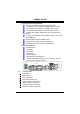
Table of Contents Chapter 1: Introduction .............................................................. 1 1.1 Features.............................................................................................. 1 1.2 Package List....................................................................................... 3 1.3 Layout ................................................................................................ 4 Chapter 2: Hardware Installation ........................................
P4M800 Pro-M7 CHAPTER 1: INTRODUCTION 1.1 FEATURES CPU Supports LGA 775. Supports Intel Pentium 4 processor up to 3.8GHz. Supports Dual Core CPU. Front side bus at the following frequency ranges: 400MHz (100MHz Core Clock) 533MHz (133MHz Core Clock) 800MHz (200MHz Core Clock) 1066MHz (266MHz Core Clock) Supports Hyper-Threading Technology. WARNING! Warranty will be void if the pin protection cap is not in place to protect the socket pin when sending this mainboard for service.
P4M800 Pro-M7 Super I/O Chip: ITE IT8705AF Provides the most commonly used legacy super I/O functionality. Environment Control initiatives: H/W Monitor. Fan Speed Controller. ITE “Smart Guardian” function. On Board IDE Support 4 IDE disk drives. Supports PIO Mode 0~4. Supports Ultra DMA 33/66/100/133 Bus Master Mode. 10/100 LAN PHY PHY: RealTek RTL8201BL/RTL8201CL. Supports 10/100 Mb/s auto-negotiation operation. Half/Full duplex capability. Supports ACPI, PCI power management.
P4M800 Pro-M7 Front Side Onboard Peripherals 1 front panel header supports front panel facilities. 1 S/PDIF out connector supports digital audio out function. 1 CD-in connector supports 1 CD-ROM audio-in device. 1 front audio header supports front panel audio function. 1 chassis open header supports PC case-opened warning function. 1 Floppy port supports 2 FDD with 360K, 720K, 1.2M, 1.44M and 2.88Mbytes. 2 USB headers support 4 USB 2.0 ports. 2 IDE connectors support 4 hard disk devices.
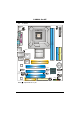
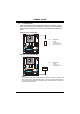
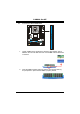
P4M800 Pro-M7 LAYOUT JATXPWR1 1.3 JKBMS1 JCFAN1 LGA775 JATXPWR2 JCOM1 CPU1 DDR2_A2 DDR2_A1 JPRNT1 JVGA1 JUSB1 IDE1 P4M800 Pro JUSBLAN1 IDE2 JUSBV1 Super I/O JAUDIO1 BIOS AGP1 BAT1 LAN PCI1 JUSB2 JFAUDIO1 JCDIN1 JAUX1 (optional) PCI2 JUSB3 JSPDIFO1 VT8237R PLUS JSATA2 JSATA1 JUSBV2 PCI3 Codec JSFAN1 CNR1 FDD1 st Note: ■ represents the 1 pin.
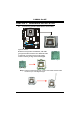
P4M800 Pro-M7 CHAPTER 2: HARDWARE INSTALLATION 2.1 INSTALLING CENTRAL PROCESSING UNIT (CPU) Special Notice: Remove Pin Cap before installation, and make good preservation for future use. When the CPU is removed, cover the Pin Cap on the empty socket to ensure pin legs won’t be damaged. Pin Cap Step 1: Pull the socket locking lever out from the socket and then raise the lever up to a 90-degree angle.
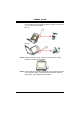
P4M800 Pro-M7 Step 2: Look for the triangular cut edge on socket, and the golden dot on CPU should point forwards this triangular cut edge. The CPU will fit only in the correct orientation. Step 2-1: Step 2-2: Step 3: Hold the CPU down firmly, and then lower the lever to locked position to complete the installation. Step 4: Put the CPU Fan and heatsink assembly on the CPU and buckle it on the retention frame. Connect the CPU FAN power cable into the JCFAN1. This completes the installation.
P4M800 Pro-M7 2.2 FAN HEADERS These fan headers support cooling-fans built in the computer. The fan cable and connector may be different according to the fan manufacturer. Connect the fan cable to the connector while matching the black wire to pin#1.
P4M800 Pro-M7 INSTALLING SYSTEM MEMORY DDR2_A1 2.3 1. Unlock a DIMM slot by pressing the retaining clips outward. Align a DIMM on the slot such that the notch on the DIMM matches the break on the Slot. 2. Insert the DIMM vertically and firmly into the slot until the retaining chip snap back in place and the DIMM is properly seated.
P4M800 Pro-M7 2.4 CONNECTORS AND SLOTS FDD1: Floppy Disk Connector The motherboard provides a standard floppy disk connector that supports 360K, 720K, 1.2M, 1.44M and 2.88M floppy disk types. This connector supports the provided floppy drive ribbon cables. 2 34 1 33 IDE1/IDE2: Hard Disk Connectors The motherboard has a 32-bit Enhanced PCI IDE Controller that provides PIO Mode 0~4, Bus Master, and Ultra DMA 33/66/100/133 functionality.
P4M800 Pro-M7 PCI1~PCI3: Peripheral Component Interconnect Slots This motherboard is equipped with 3 standard PCI slots. PCI stands for Peripheral Component Interconnect, and it is a bus standard for expansion cards. This PCI slot is designated as 32 bits. PCI1 PCI2 PCI3 AGP1: Accelerated Graphics Port Slot Your monitor will attach directly to that video card. This motherboard supports video cards for PCI slots, but it is also equipped with an Accelerated Graphics Port (AGP).
P4M800 Pro-M7 CNR1: Communication Network Riser Slot The CNR specification is an open Industry Standard Architecture, and it defines a hardware scalable riser card interface, which supports modem only.
P4M800 Pro-M7 CHAPTER 3: HEADERS & JUMPERS SETUP 3.1 HOW TO SETUP JUMPERS The illustration shows how to set up jumpers. When the jumper cap is placed on pins, the jumper is “close”, if not, that means the jumper is “open”. Pin opened 3.2 Pin closed Pin1-2 closed DETAIL SETTINGS JUSBV1/JUSBV2: Power Source Headers for USB ports Pin 1-2 Close: JUSBV1: +5V for USB ports at JUSB1 and JUSBLAN1. JUSBV2: +5V for USB ports at front panel (JUSB2/JUSB3).
P4M800 Pro-M7 JATXPWR1: ATX Power Source Connector This connector allows user to connect 20-pin power connector on the ATX power supply. 10 1 20 11 Pin 1 2 3 4 5 6 7 8 9 10 11 12 13 14 15 16 17 18 19 20 Assignment +3.3V +3.3V Ground +5V Ground +5V Ground PW_OK Standby Voltage +5V +12V +3.3V -12V Ground PS_ON Ground Ground Ground -5V +5V +5V JATXPWR2: ATX Power Source Connector By connecting this connector, it will provide +12V to CPU power circuit.
P4M800 Pro-M7 JUSB2/JUSB3: Headers for USB 2.0 Ports at Front Panel This header allows user to connect additional USB cable on the PC front panel, and also can be connected with internal USB devices, like USB card reader. Pin 1 2 3 4 5 6 7 8 9 10 JUSB2 2 10 1 9 Assignment +5V (fused) +5V (fused) USBUSBUSB+ USB+ Ground Ground Key NC JUSB3 JPANEL1: Front Panel Header This 24-pin connector includes Power-on, Reset, HDD LED, Power LED, Sleep button, speaker and IrDA Connection.
P4M800 Pro-M7 JCDIN1: CD-ROM Audio-in Connector This connector allows user to connect the audio source from the variaty devices, like CD-ROM, DVD-ROM, PCI sound card, PCI TV turner card etc.. Pin 1 2 3 4 4 Assignment Left Channel Input Ground Ground Right Channel Input 1 JFAUDIO1: Front Panel Audio Header This header allows user to connect the front audio output cable with the PC front panel. It will disable the output on back panel audio connectors.
P4M800 Pro-M7 JCMOS1: Clear CMOS Header By placing the jumper on pin2-3, it allows user to restore the BIOS safe setting and the CMOS data, please carefully follow the procedures to avoid damaging the motherboard. 1 3 Pin 1-2 Close: Normal Operation (Default). 1 1 3 3 Pin 2-3 Close: Clear CMOS data. ※ Clear CMOS Procedures: 1. 2. 3. 4. 5. 6. Remove AC power line. Set the jumper to “Pin 2-3 Close”. Wait for five seconds. Set the jumper to “Pin 1-2 Close”. Power on the AC.
P4M800 Pro-M7 JSATA1~JSATA2: Serial ATA Connectors The motherboard has a PCI to SATA Controller with 2 channels SATA interface, it satisfies the SATA 1.0 spec and with transfer rate of 1.5GB/s. 7 4 Pin 1 2 3 4 5 6 7 1 Assignment Ground TX+ TXGround RXRX+ Ground JSATA1 1 4 7 JSPDIFO1: Digital Audio-out Connector This connector allows user to connect the PCI bracket SPDIF output header.
P4M800 Pro-M7 CHAPTER 4: USEFUL HELP 4.1 AWARD BIOS BEEP CODE Beep Sound One long beep followed by two short beeps High-low siren sound Meaning Video card not found or video card memory bad CPU overheated System will shut down automatically One Short beep when system boot-up No error found during POST Long beeps every other second No DRAM detected or install 4.2 EXTRA INFORMATION A.
P4M800 Pro-M7 B. CPU Overheated If the system shutdown automatically after power on system for seconds, that means the CPU protection function has been activated. When the CPU is over heated, the motherboard will shutdown automatically to avoid a damage of the CPU, and the system may not power on again. In this case, please double check: 1. The CPU cooler surface is placed evenly with the CPU surface. 2. CPU fan is rotated normally. 3. CPU fan speed is fulfilling with the CPU speed.
P4M800 Pro-M7 4.3 TROUBLESHOOTING Problem Solution No power to the system at all 1. Make sure power cable is Power light don’t illuminate, fan securely plugged in. inside power supply does not turn 2. Replace cable. on. 3. Contact technical support. 2. Indicator light on keyboard does not turn on. System inoperative. Keyboard lights Using even pressure on both ends of are on, power indicator lights are lit, the DIMM, press down firmly until the and hard drive is spinning. module snaps into place.
P4M800 Pro-M7 CHAPTER 5: WARPSPEEDER™ 5.1 INTRODUCTION [WarpSpeeder™], a new powerful control utility, features three user-friendly functions including Overclock Manager, Overvoltage Manager, and Hardware Monitor. With the Overclock Manager, users can easily adjust the frequency they prefer or they can get the best CPU performance with just one click. The Overvoltage Manager, on the other hand, helps to power up CPU core voltage and Memory voltage.
P4M800 Pro-M7 5.3 INSTALLATION 1. Execute the setup execution file, and then the following dialog will pop up. Please click “Next” button and follow the default procedure to install. 2. When you see the following dialog in setup procedure, it means setup is completed. If the “Launch the WarpSpeeder Tray Utility” checkbox is checked, the Tray Icon utility and [WarpSpeeder™] utility will be automatically and immediately launched after you click “Finish” button.
P4M800 Pro-M7 5.4 [WARPSPEEDER™] INCLUDES 1 TRAY ICON AND 5 PANELS 1. Tray Icon: Whenever the Tray Icon utility is launched, it will display a little tray icon on the right side of Windows Taskbar. This utility is responsible for conveniently invoking [WarpSpeeder™] Utility. You can use the mouse by clicking the left button in order to invoke [WarpSpeeder™] directly from the little tray icon or you can right-click the little tray icon to pop up a popup menu as following figure.
P4M800 Pro-M7 2. Main Panel If you click the tray icon, [WarpSpeeder™] utility will be invoked. Please refer to the following figure; the utility’s first window you will see is Main Panel. Main Panel contains features as follows: a. b. c. Display the CPU Speed, CPU external clock, Memory clock, AGP clock, and PCI clock information. Contains About, Voltage, Overclock, and Hardware Monitor Buttons for invoking respective panels.
P4M800 Pro-M7 3. Voltage Panel Click the Voltage button in Main Panel, the button will be highlighted and the Voltage Panel will slide out to up as the following figure. In this panel, you can decide to increase CPU core voltage and Memory voltage or not. The default setting is “No”. If you want to get the best performance of overclocking, we recommend you click the option “Yes”.
P4M800 Pro-M7 4. Overclock Panel Click the Overclock button in Main Panel, the button will be highlighted and the Overclock Panel will slide out to left as the following figure. Overclock Panel contains the these features: a. “–3MHz button”, “-1MHz button”, “+1MHz button”, and “+3MHz button”: provide user the ability to do real-time overclock adjustment. Warning: Manually overclock is potentially dangerous, especially when the overclocking percentage is over 110 %.
P4M800 Pro-M7 c. d. “Auto-overclock button”: User can click this button and [WarpSpeeder™] will set the best and stable performance and frequency automatically. [WarpSpeeder™] utility will execute a series of testing until system fail. Then system will do fail-safe reboot by using Watchdog function. After reboot, the [WarpSpeeder™] utility will restore to the hardware default setting or load the verified best and stable frequency according to the Recovery Dialog’s setting.
P4M800 Pro-M7 6. About Panel Click the “about” button in Main Panel, the button will be highlighted and the About Panel will slide out to up as the following figure. In this panel, you can get model name and detail information in hints of all the chipset that are related to overclocking. You can also get the mainboard’s BIOS model and the Version number of [WarpSpeeder™] utility.
P4M800 Pro-M7 Note: Because the overclock, overvoltage, and hardware monitor features are controlled by several separate chipset, [WarpSpeeder™] divide these features to separate panels. If one chipset is not on board, the correlative button in Main panel will be disabled, but will not interfere other panels’ functions. This property can make [WarpSpeeder™] utility more robust.