TP35D2-A7 Setup Manual FCC Information and Copyright This equipment has been tested and found to comply with the limits of a Class B digital device, pursuant to Part 15 of the FCC Rules. These limits are designed to provide reasonable protection against harmful interference in a residential installation. This equipment generates, uses, and can radiate radio frequency energy and, if not installed and used in accordance with the instructions, may cause harmful interference to radio communications.
Table of Contents Chapter 1: Introduction ........................................ 1 1.1 1.2 1.3 1.4 1.5 1.6 Before You Start......................................................................................... 1 Package Checklist ..................................................................................... 1 Motherboard Features.............................................................................. 2 Rear Panel Connectors (for Ver 5.x)....................................................
TP35D2-A7 CHAPTER 1: INTRODUCTION 1.1 BEFORE YOU START Thank you for choosing our product. Before you start installing the motherboard, please make sure you follow the instructions below: 1.2 Prepare a dry and stable working environment with sufficient lighting. Always disconnect the computer from power outlet before operation.
Motherboard Manual 1.3 MOTHERBOARD FEATURES Ver 5.x CPU FSB Chipset Ver 6.
TP35D2-A7 Ver 5.x Ver 6.x Realtek RTL 8110SC / 8100C (optional) LAN Sound Codec 10 / 100 Mb/s / 1Gb/s auto negotiation (Gigabit 10 / 100 Mb/s / 1Gb/s auto negotiation (Gigabit bandwidth is for RTL 8110SC only) bandwidth is for RTL 8110SC only) Half / Full duplex capability Half / Full duplex capability ALC888 ALC861VD 7.1 channels audio out 5.
Motherboard Manual 1.4 REAR PANEL CONNECTORS (FOR VER 5.X) PS/2 Mouse PS/ 2 Keyboard LAN COM1 USBX2 USBX2 Center 1.5 Audio Jack USBX2 Line In Rear Line Out Side Mic In REAR PANEL CONNECTORS (FOR VER 6.
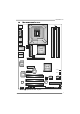
TP35D2-A7 1.6 MOTHERBOARD LAYOUT JCFAN1 JKBMS1 LGA775 JPRNT1 JCOM1 CPU1 JRJ45USB1 DDR2_B2 DDR2_B1 JUSB1 DDR2_A2 DDR2_A1 JUSB2 Intel P35 JATXPWR1 JAUDIO1 (for Ver 5.x) JAUDIO2 (for Ver 6.
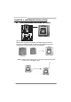
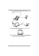
Motherboard Manual CHAPTER 2: HARDWARE INSTALLATION 2.1 INSTALLING CENTRAL PROCESSING UNIT (CPU) Special Notice: Remove Pin Cap before installation, and make good preservation for future use. When the CPU is removed, cover the Pin Cap on the empty socket to ensure pin legs won’t be damaged. Pin Cap Step 1: Pull the socket locking lever out from the socket and then raise the lever up to a 90-degree angle.
TP35D2-A7 Step 2: Look for the triangular cut edge on socket, and the golden dot on CPU should point forwards this triangular cut edge. The CPU will fit only in the correct orientation. Step 2-1: Step 2-2: Step 3: Hold the CPU down firmly, and then lower the lever to locked position to complete the installation. Step 4: Put the CPU Fan and heatsink assembly on the CPU and buckle it on the retention frame. Connect the CPU FAN power cable into the JCFAN1. This completes the installation.
Motherboard Manual 2.2 FAN HEADERS These fan headers support cooling-fans built in the computer. The fan cable and connector may be different according to the fan manufacturer. Connect the fan cable to the connector while matching the black wire to pin#1.
TP35D2-A7 2.3 INSTALLING SYSTEM MEMORY DDR2_B1 DDR2_B2 DDR2_A1 DDR2_A2 A. Memory Modules 1. Unlock a DIMM slot by pressing the retaining clips outward. Align a DIMM on the slot such that the notch on the DIMM matches the break on the Slot. 2. Insert the DIMM vertically and firmly into the slot until the retaining chip snap back in place and the DIMM is properly seated. B.
Motherboard Manual C. Dual Channel Memory installation To trigger the Dual Channel function of the motherboard, the memory module must meet the following requirements: Install memory module of the same density in pairs, shown in the following table. Dual Channel Status DDR2_A1 DDR2_A2 DDR2_B1 DDR2_B2 Enabled O X O X Enabled X O X O Enabled O O O O (O means memory installed, X means memory not installed.
TP35D2-A7 2.4 CONNECTORS AND SLOTS FDD1: Floppy Disk Connector The motherboard provides a standard floppy disk connector that supports 360K, 720K, 1.2M, 1.44M and 2.88M floppy disk types. This connector supports the provided floppy drive ribbon cables. 33 1 34 2 IDE1: Hard Disk Connector The motherboard has a 32-bit Enhanced PCI IDE Controller that provides PIO Mode 0~4, Bus Master, and Ultra DMA 33/66/100/133 functionality.
Motherboard Manual PEX16_1: PCI-Express x16 Slot - PCI-Express 1.0a compliant. Maximum theoretical realized bandwidth of 4GB/s simultaneously per direction, for an aggregate of 8GB/s totally. PEX4_1: PCI-Express x4 Slot - PCI-Express 1.0a compliant. Maximum theoretical realized bandwidth of 1GB/s simultaneously per direction, for an aggregate of 2GB/s totally. PEX1_1: PCI-Express Slot - PCI-Express 1.0a compliant.
TP35D2-A7 CHAPTER 3: HEADERS & JUMPERS SETUP 3.1 HOW TO SETUP JUMPERS The illustration shows how to set up jumpers. When the jumper cap is placed on pins, the jumper is “close”, if not, that means the jumper is “open”. Pin opened 3.2 Pin closed Pin1-2 closed DETAIL SETTINGS JPANEL1: Front Panel Header This 16-pin connector includes Power-on, Reset, HDD LED, Power LED, Sleep button and speaker connection. It allows user to connect the PC case’s front panel switch functions.
Motherboard Manual JATXPWR2: ATX Power Source Connector JATXPW2 allows user to connect 24-pin power connector on the ATX power supply. 13 1 24 12 Pin Assignment Pin Assignment 13 14 15 16 17 18 19 20 21 22 23 24 +3.3V -12V Ground PS_ON Ground Ground Ground NC +5V +5V +5V Ground 1 2 3 4 5 6 7 8 9 10 11 12 +3.3V +3.3V Ground +5V Ground +5V Ground PW_OK Standby Voltage+5V +12V +12V +3.3V JATXPWR1: ATX Power Source Connector By connecting this connector, it will provide +12V to CPU power circuit.
TP35D2-A7 JUSB3/JUSB4/JUSB5: Headers for USB 2.0 Ports at Front Panel This header allows user to connect additional USB cable on the PC front panel, and also can be connected with internal USB devices, like USB card reader. Pin 1 2 3 4 5 6 7 8 9 10 JUSB5 JUSB4 JUSB3 9 1 10 2 Assignment +5V (fused) +5V (fused) USBUSBUSB+ USB+ Ground Ground Key NC JAUDIOF1: Front Panel Audio Header This header allows user to connect the front audio output cable with the PC front panel.
Motherboard Manual JCMOS1: Clear CMOS Header By placing the jumper on pin2-3, it allows user to restore the BIOS safe setting and the CMOS data, please carefully follow the procedures to avoid damaging the motherboard. 3 1 Pin 1-2 Close: Normal Operation (default). 3 3 1 1 Pin 2-3 Close: Clear CMOS data. ※ Clear CMOS Procedures: 1. 2. 3. 4. 5. 6. Remove AC power line. Set the jumper to “Pin 2-3 close”. Wait for five seconds. Set the jumper to “Pin 1-2 close”. Power on the AC.
TP35D2-A7 JSPDIF_OUT1: Digital Audio-out Connector This connector allows user to connect the PCI bracket SPDIF output header. Pin 1 2 3 3 Assignment +5V SPDIF_OUT Ground 1 JSPDIF_IN1: Digital Audio-in Connector (Optional) This connector allows user to connect the PCI bracket SPDIF input header.
Motherboard Manual On-Board LED Indicators There are 2 LED indicators on the motherboard to show system status. LED2 LED1 LED1 and LED2: These 2 LED indicate system power on diagnostics. Please refer to the table below for different messages: LED1 ON ON OFF OFF LED2 ON OFF ON OFF Message Normal Memory Error VGA Error Abnormal: CPU / Chipset error. On-Board Buttons There are 2 on-board buttons. RSTSW2 PWRSW1 PWRSW1: This is an on-board Power Switch button. RSTSW2: This is an on-board Reset button.
TP35D2-A7 JPRNT1: Printer Port Connector This header allows you to connector printer on the PC.
Motherboard Manual CHAPTER 4: OVERCLOCK QUICK GUIDE 4.1 T-POWER INTRODUCTION Biostar T-Power is a whole new utility that is designed for overclock users. Based on many precise tests, Biostar Engineering Team (BET) has developed this ultimate overclock engine to raise system performance. No matter whether under BIOS or Windows interface, T-Power is able to present the best system state according to users’ overclock setting. T-Power BIOS Features: Overclocking Navigator Engine (O.N.E.
TP35D2-A7 4.2 T-POWER BIOS FEATURE A. Overclocking Navigator Engine (O.N.E.): ONE provides two powerful overclocking engines: MOS and AOS for both Elite and Casual overclockers. Manual Overclock System (M.O.S.) MOS is designed for experienced overclock users. It allows users to customize personal overclock settings.
Motherboard Manual CPU Clock Ratio & CPU Clock: CPU Clock Ratio x CPU Clock = CPU Frequency. CPU Frequency is directly in proportion to system performance. To maintain the system stability, CPU voltage needs to be increased also when raising CPU frequency. PCI-E Clock Select: It helps to increase VGA card performance. System Me mory Frequency: To get better system performance, sometimes downgrading the memory frequency is necessary when CPU frequency is adjusted over the upper limit.
TP35D2-A7 V6 Tech Engine: This setting will raise about 10%~15% of whole system performance. V8 Tech Engine: This setting will raise about 15%~25% of whole system performance. V12 Tech Engine: This setting will raise about 25%~30% of whole system performance.
Motherboard Manual B. CMOS Reloading Program (C.R.P.): It allows users to save different CMOS settings into BIOS-ROM. Users are able to reload any saved CMOS setting for customizing system configurations. Moreover, users are able to save an ideal overclock setting during overclock operation. There are 50 sets of record addresses in total, and users are able to name the CMOS data according to personal preference.
TP35D2-A7 C. Memory Integration Test (M.I.T.): This function is under “Overclocking Navigator Engine” item. MIT allows users to test memory compatibilities, and no extra devices or software are needed. Step 1: The default setting under this item is “Disabled”; the condition parameter should be changed to “Enable” to proceed this test. ↓ Step 2: Save and Exit from CMOS setup and reboot the system to activate this test. Run this test for 5 minutes (minimum) to ensure the memory stability.
Motherboard Manual D. Self Recovery System (S.R.S.): This function can’t be seen under T-Power BIOS setup; and is always on whenever the system starts up. However, it can prevent system hang-up due to inappropriate overclock actions. When the system hangs up, S.R.S. will automatically log in the default BIOS setting, and all overclock settings will be re-configured. E. Integrated Flash Program (I.F.P.): IFP is a safe and quick way to upgrade BIOS. Step 1: Go to Biostar website (http://www.biostar.com.
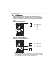
TP35D2-A7 4.3 T-POWER WINDOWS FEATURE 1. Desktop Icon After the T-Utility has been installed, a T-Utility icon will appear on the desktop, just like the icon shown below. Now you can launch the T-Utility simply by double-clicking the desktop icon. 2. Main Panel If you double-click the desktop icon, T-Utility will be launched. Please refer to the following figure; the utility’s first window you will see is Main Panel. Main Panel contains features as follows: a. b.
Motherboard Manual 3. Overclock/Overvoltage Panel Click the Overclock/Overvoltage button in the Main Panel, the button will be highlighted and the Overclock/Overvoltage Panel will show up as the following figure. As you can see, the Overclock Panel is on the upper side, and the Overvoltage Panel is on the lower side.
TP35D2-A7 Overclock Panel contains these features: a. “Auto-Overclock”: User can click this button and T-Utility will set the best and stable performance and frequency automatically. A warning dialog as below will show up to notify you that the system may become unstable, click on “OK” to continue. Then T-Utility will execute a series of testing until system fail. Then system will do fail-safe reboot by using Watchdog function.
Motherboard Manual e. “Save / Open Setting”: Click Save button to save current setting to a file, and click Open button to load a previously saved setting. f. “Panel Color”: Click this button to change the color of the panel. Overvoltage Panel contains these features: a. b. c. “CPU Voltage”: This function allows user to adjust CPU voltage. increase or “-“ to decrease the CPU voltage. Click on “+” to “Memory Voltage”: This function allows user to adjust Memory voltage.
TP35D2-A7 5. About Panel Click the “about” button in Main Panel, the button will be highlighted and the About Panel will show up as the following figure. In this panel, you can get model name and detail information in hints of all the chipset that are related to overclocking. You can also get the the version number of T-Utility. Note: Because the overclock, overvoltage, and hardware monitor features are controlled by several separate chipset, T-Utility divides these features to separate panels.
Motherboard Manual CHAPTER 5: USEFUL HELP 5.1 DRIVER INSTALLATION NOTE After you installed your operating system, please insert the Fully Setup Driver CD into your optical drive and install the driver for better system performance. You will see the following window after you insert the CD The setup guide will auto detect your motherboard and operating system. Note: If this window didn’t show up after you insert the Driver CD, please use file browser to locate and execute the file SETUP.
TP35D2-A7 5.2 AWARD BIOS BEEP CODE Beep Sound Meaning One long beep followed by two short beeps High-low siren sound Video card not found or video card memory bad CPU overheated System will shut down automatically One Short beep when system boot-up Long beeps every other second No error found during POST No DRAM detected or install 5.3 EXTRA INFORMATION A. BIOS Update After you fail to update BIOS or BIOS is invaded by virus, the Boot-Block function will help to restore BIOS.
Motherboard Manual B. CPU Overheated If the system shutdown automatically after power on system for seconds, that means the CPU protection function has been activated. When the CPU is over heated, the motherboard will shutdown automatically to avoid a damage of the CPU, and the system may not power on again. In this case, please double check: 1. The CPU cooler surface is placed evenly with the CPU surface. 2. CPU fan is rotated normally. 3. CPU fan speed is fulfilling with the CPU speed.
TP35D2-A7 5.4 TROUBLESHOOTING Probable Solution 1. No power to the system at all 1. Make sure power cable is Power light don’t illuminate, fan securely plugged in. inside power supply does not turn 2. Replace cable. on. 3. Contact technical support. 2. Indicator light on keyboard does not turn on. System inoperative. Keyboard lights Using even pressure on both ends of are on, power indicator lights are lit, the DIMM, press down firmly until the and hard drive is spinning. module snaps into place.
Motherboard Manual APPENDENCIES: SPEC IN OTHER LANGUAGE GERMAN Ver 5.x Ver 6.
TP35D2-A7 Ver 5.x Ver 6.
Motherboard Manual FRANCE Ver 5.x Ver 6.
TP35D2-A7 Ver 5.x Ver 6.
Motherboard Manual ITALIAN Ver 5.x CPU Ver 6.
TP35D2-A7 Ver 5.x LAN Supporto audio HD Alloggi Connettori su scheda Ver 6.
Motherboard Manual SPANISH Ver 5.x Ver 6.
TP35D2-A7 Ver 5.x Soporte de sonido HD ALC888 ALC861VD Soporte de sonido de Alta Definición Soporte de sonido de Alta Definición Salida de sonido de 7.1 canales Ranura PCI Ranuras Conectores en placa Ver 6.x Salida de sonido de 5.
Motherboard Manual PORTUGUESE Ver 5.x Ver 6.
TP35D2-A7 Ver 5.x Suporte para áudio de alta definição Ranhuras Conectores na placa Ver 6.x ALC888 ALC861VD Suporta a especificação High-Definition Audio Suporta a especificação High-Definition Audio Saída de áudio de 7.1 canais Saída de áudio de 5.
Motherboard Manual POLISH Ver 5.x Ver 6.
TP35D2-A7 Ver 5.x Obsługa audio HD Gniazda Złącza wbudowane Ver 6.x ALC888 ALC861VD Obsługa High-Definition Audio Obsługa High-Definition Audio 5.1 kanałowe wyjście audio 7.
Motherboard Manual RUSSIAN Ver 5.x CPU Ver 6.
TP35D2-A7 Ver 5.x Ver 6.x только для гигабитного физического уровня) только для гигабитного физического уровня) Звуковая поддержка жесткого диска Слоты Частичная / полная дуплексная способность Частичная / полная дуплексная способность ALC888 ALC861VD Звуковая поддержка High-Definition Звуковая поддержка High-Definition 7.1канальный звуковой выход 5.
Motherboard Manual ARABIC Ver 6.x Ver 5.
TP35D2-A7 Ver 5.x دﻋﻢ اﻝﺼﻮت ﻋﺎﻝﻲ اﻝﺘﻌﺮیﻒ Ver 6.x RTL 8110SCاﻟﻨﻄﺎق اﻟﺘﺮددي ﻟﻠﺠﻴﺠﺎﺑﺖ ﻣﻘﺼﻮر ﻓﻘﻂ ﻋﻠﻰ RTL 8110SCاﻟﻨﻄﺎق اﻟﺘﺮددي ﻟﻠﺠﻴﺠﺎﺑﺖ ﻣﻘﺼﻮر ﻓﻘﻂ ﻋﻠﻰ إﻣﻜﺎﻥﻴﺔ اﻟﻨﻘﻞ اﻟﻤﺰدوج اﻟﻜﺎﻣﻞ/اﻟﻨﺼﻔﻲ إﻣﻜﺎﻥﻴﺔ اﻟﻨﻘﻞ اﻟﻤﺰدوج اﻟﻜﺎﻣﻞ/اﻟﻨﺼﻔﻲ ALC888 ALC861VD ﺕﺪﻋﻢ ﺕﻘﻨﻴﺔ اﻟﺼﻮت ﻋﺎﻟﻲ اﻟﺘﻌﺮﻳﻒ ﻣﻦ Intelﺕﺪﻋﻢ ﺕﻘﻨﻴﺔ اﻟﺼﻮت ﻋﺎﻟﻲ اﻟﺘﻌﺮﻳﻒ ﻣﻦ 7.1ﻗﻨﻮات ﻟﺨﺮج اﻟﺼﻮت 5.
Motherboard Manual JAPANESE Ver 5.x CPU Ver 6.
TP35D2-A7 Ver 5.x HDオーディ オのサポート スロット オンボードコ ネクタ Ver 6.x 半/全二重機能 半/全二重機能 ALC888 ALC861VD ハイデフィニションオーディオのサポート ハイデフィニションオーディオのサポート 7.1 チャンネルオーディオアウト 5.
TP35D2-A7 BIOS Setup BIOS Setup ................................................................................................ 1 1 Main Menu ............................................................................................. 3 2 Standard CMOS Features..................................................................... 7 3 Advanced BIOS Features ...................................................................... 9 4 Advanced Chipset Features...................................................
TP35D2-A7 BIOS Setup Introduction The purpose of this manual is to describe the settings in the Phoenix-Award™ BIOS Setup program on this motherboard. The Setup program allows users to modify the basic system configuration and save these settings to CMOS RAM. The power of CMOS RAM is supplied by a battery so that it retains the Setup information when the power is turned off. Basic Input-Output System (BIOS) determines what a computer can do without accessing programs from a disk.
TP35D2-A7 ACPI Support Phoenix-Award ACPI BIOS support Version 1.0b of Advanced Configuration and Power interface specification (ACPI). It provides ASL code for power management and device configuration capabilities as defined in the ACPI specification, developed by Microsoft, Intel and Toshiba. PCI Bus Support This PHOENIX-AWARD BIOS also supports Version 3.0 of the Intel PCI (Peripheral Component Interconnect) local bus specification.
TP35D2-A7 1 Main Menu Once you enter Phoenix-Award BIOS™ CMOS Setup Utility, the Main Menu will appear on the screen. The Main Menu allows you to select from several setup functions. Use the arrow keys to select among the items and press to accept and enter the sub-menu. !! WARNING !! For better system performance, the BIOS firmware is being continuously updated. The BIOS information described in this manual (Figure 1, 2, 3, 4, 5, 6, 7, 8, 9,10) is for your reference only.
TP35D2-A7 Advanced BIOS Features This submenu allows you to configure advanced features of the BIOS. Advanced Chipset Features This submenu allows you to configure special chipset features. Integrated Peripherals This submenu allows you to configure certain IDE hard drive options and Programmed Input/ Output features. Power Management Setup This submenu allows you to configure the power management features.
TP35D2-A7 Load Optimized Defaults This selection allows you to reload the BIOS when problem occurs during system booting sequence. These configurations are factory settings optimized for this system. A confirmation message will be displayed before defaults are set. Set Supervisor Password Setting the supervisor password will prohibit everyone except the supervisor from making changes using the CMOS Setup Utility. You will be prompted with to enter a password.
TP35D2-A7 Exit Without Saving Abandon all changes made during the current session and exit setup. Confirmation message will be displayed before proceeding. Integrate Flashing Program This submenu allows you to upgrade bios.
TP35D2-A7 2 Standard CMOS Features The items in Standard CMOS Setup Menu are divided into several categories. Each category includes no, one or more than one setup items. Use the arrow keys to highlight the item and then use the or keys to select the value you want in each item. Figure 2: Standard CMOS Setup Main Menu Selections This table shows the items and the available options on the Main Menu. Item Options Description Date mm : dd : yy Set the system date.
TP35D2-A7 Item Options Description IDE Channel 1 Master / Slave Options are in its sub menu. Press to enter the sub menu of detailed options. 360K, 5.25 in 1.2M, 5.25 in Drive A 720K, 3.5 in 1.44M, 3.5 in Select the type of floppy disk drive installed in your system. 2.88M, 3.5 in None All Errors No Errors Halt On All, but Keyboard All, but Diskette Select the situation in which you want the BIOS to stop the POST process and notify you.
TP35D2-A7 3 Advanced BIOS Features Figure 3: Advanced BIOS Setup 9
TP35D2-A7 CPU Feature Delay Prior to Thermal Set this item to enable the CPU Thermal function to engage after the specified time. The Choices: 4 Min, 8 Min, 16Min (default), 32 Min. Thermal Management This option allows you to select the way to control the “Thermal Management.” The Choices: Thermal Monitor 1 (default), Thermal Monitor 2.
TP35D2-A7 Limit CPUID MaxVal Set Limit CPUID MaxVal to 3, it should be “Disabled” for Windows XP. The Choices: Disabled (default), Enabled. C1E Function This item allows you to configure the Enhanced Halt State (C1E) function, which may reduce the power consumption of your system when the system is idle. The Choices: Auto (default),Disabled. Execute Disable Bit This item allows you to configure the Execute Disabled Bit function, which protects your system from buffer overflow attacks.
TP35D2-A7 Boot Seq & Floppy Setup This item allows you to setup boot sequence & Floppy. Hard Disk Boot Priority The BIOS will attempt to arrange the Hard Disk boot sequence automatically. You can change the Hard Disk booting sequence here. The Choices: Pri. Master, Pri. Slave, Sec. Master, Sec. Slave, USB HDD0, USB HDD1, USB HDD2, and Bootable Add-in Cards.
TP35D2-A7 First/Second/Third Boot Device The BIOS will attempt to load the operating system in this order. The Choices: Floppy, LS120, Hard Disk, CDROM, ZIP100, USB-FDD, USB-ZIP, USB-CDROM, LAN, Disabled. Boot Other Device When enabled, BIOS will try to load the operating system from other device when it failed to load from the three devices above. The Choices: Enabled (default), Disabled.
TP35D2-A7 Boot Up NumLock Status Selects the NumLock State after the system switched on. The Choices: On (default) Numpad is number keys. Off Numpad is arrow keys. Gate A20 Option Select if chipset or keyboard controller should control Gate A20. Normal A pin in the keyboard controller controls GateA20. Fast (default) Lets chipset control Gate A20. Typematic Rate Setting When a key is held down, the keystroke will repeat at a rate determined by the keyboard controller.
TP35D2-A7 APIC MODE Selecting Enabled enables APIC device mode reporting from the BIOS to the operating system. The Choices: Enabled (default), Disabled. MPS Version Control For OS The BIOS supports version 1.1 and 1.4 of the Intel multiprocessor specification. Select version supported by the operation system running on this computer. The Choices: 1.4 (default), 1.1. OS Select For DRAM > 64MB A choice other than Non-OS2 is only used for OS2 systems with memory exceeding 64MB.
TP35D2-A7 4 Advanced Chipset Features This submenu allows you to configure the specific features of the chipset installed on your system. This chipset manage bus speeds and access to system memory resources, such as DRAM. It also coordinates communications with the PCI bus. The default settings that came with your system have been optimized and therefore should not be changed unless you are suspicious that the settings have been changed incorrectly.
TP35D2-A7 Memory Hole At 15M-16M You can reserve this area of system memory for ISA adapter ROM. When this area is reserved it cannot be cached. Check the user information of peripherals that need to use this area of system memory for the memory requirements. The Choices: Disabled (default), Enabled. PEG Force X1 When using on-chip VGA, this item has to be set as X1.
TP35D2-A7 5 Integrated Peripherals Figure 5.
TP35D2-A7 OnChip IDE Device Highlight the “Press Enter” label next to the “OnChip IDE Device” label and press enter key will take you a submenu with the following options: IDE HDD Block Mode Block mode is also called block transfer, multiple commands, or multiple sectors read / write.
TP35D2-A7 On-chip Secondary PCI IDE This item allows you to enable or disable the primary / secondary IDE Channel. The Choices: Enabled (default), Disabled. IDE Primary/Secondary/Master/Slave UDMA Ultra DMA function can be implemented if it is supported by the IDE hard drives in your system. As well, your operating environment requires a DMA driver (Windows 95 or OSR2may need a third party IDE bus master driver).
TP35D2-A7 Onboard Serial Port 1 Select an address and corresponding interrupt for the first and second serial ports. The Choices: 3F8/IRQ4 (default), Disabled, 2F8/IRQ3, 3E8/IRQ4, 2E8/IRQ3, Auto. Onboard Parallel Port This item allows you to determine access onboard parallel port controller with which I/O Address. The Choices: 378/IRQ7 (default), 278/IRQ5, 3BC/IRQ7, Disabled. Parallel Port Mode This item allows you to determine how the parallel port should function. The default value is SPP.
TP35D2-A7 USB Device Setting Highlight the “Press Enter” label next to the “Onboard Device” label and press the enter key will take you a submenu with the following options: USB 1.0/2.0 Controller If your system contains a Universal Serial Bus (USB) controller, This entry is to enable/disable Enhanced host controller . The Choices: Enabled (default), Disabled. USB Operation Mode Auto decide USB device operation mode. [High Speed]: If USB device was high speed device,then it operated on high speed mode.
TP35D2-A7 UFDDA/UFDDB The Choices: USB Floppy (default). No Device [Auto]: According to contents of USB MSD decide boot up type. [FDD Mode]: The USB MSD always boot up as floppy disk. [HDD Mode]: The USB MSD always boot up as hard disk. The Choices: Auto mode (default), FDD mode, HDD mode. PCIE to PATA IDE cntrlr The Choices: Auto (default), Disabled. PCI-E Compliancy Mode This item allows you to select the PCI-E Compliancy Mode. The Choices: v1.0a (default), v1.0.
TP35D2-A7 6 Power Management Setup The Power Management Setup Menu allows you to configure your system to utilize energy conservation and power up/power down features. Figure 6.
TP35D2-A7 ACPI & Wake Up Events ACPI Function This item displays the status of the Advanced Configuration and Power Management (ACPI). The Choices: Enabled (default), Disabled. ACPI Suspend Type The item allows you to select the suspend type under the ACPI operating system. The Choices: S1 (POS) (default) Power on Suspend S3 (STR) Suspend to RAM S1 & S3 POS+STR Run VGABIOS if S3 Resume Choosing Enabled will make BIOS run VGA BIOS to initialize the VGA card when system wakes up from S3 state.
TP35D2-A7 Wake-Up by PCI card When you select “Enable”, a PME signal from PCI card returns the system to Full On state. The Choices: Disabled (default), Enabled. PCI Express PME The Choices: Disabled (default), Enabled. Power On by Ring An input signal on the serial Ring Indicator (RI) line (in other words, an incoming call on the modem) awakens the system from a soft off state. The Choices: Enabled, Disabled (default).
TP35D2-A7 PWRON After PWR-Fail This setting specifies how your system should behave after a power fail or interrupts occurs. By choosing off will leave the computer in the power off state. Choosing On will reboot the computer. Former-Sts will restore the system to the status before power failure or interrupt occurs. The Choices: Off (default), On, Former-Sts. Reload Timer Events Primary/Secondary IDE 0/1 You can enable or disable Primary or Secondary RAID 0 or RAID 1 function under this item.
TP35D2-A7 Power Management This category allows you to select the power saving method and is directly related to the following modes: 1. HDD Power Down. 2. Suspend Mode. There are three options of Power Management, three of which have fixed mode settings Min. Saving (default) Minimum power management. Suspend Mode = 1 hr. HDD Power Down = 15 min Max. Saving Maximum power management only available for sl CPU’s. Suspend Mode = 1 min. HDD Power Down = 1 min.
TP35D2-A7 Suspend Type Select the Suspend Type. The Choices: Stop Grant (default), PwrOn Suspend. Modem Use IRQ This determines the IRQ, which can be applied in MODEM use. The Choices: 3 (default), 4, 5, 7, 9, 10, 11, NA. Suspend Mode The item allows you to adjust the system idle time before suspend. The Choices: Disabled, 1 Min, 2 Min, 4 Min, 6 Min, 8 Min, 10 Min, 20 Min, 30 Min, 40 Min, 1 Hour (default).
TP35D2-A7 7 PnP/PCI Configurations This section describes configuring the PCI bus system. PCI, or Personal Computer Interconnect, is a system which allows I/O devices to operate at speeds nearing the speed of the CPU itself uses when communicating with its own special components. This section covers some very technical items and it is strongly recommended that only experienced users should make any changes to the default settings.
TP35D2-A7 IRQ Resources This submenu will allow you to assign each system interrupt a type, depending on the type of device using the interrupt. When you press the “Press Enter” tag, you will be directed to a submenu that will allow you to configure the system interrupts. This is only configurable when “Resources Controlled By” is set to “Manual”.
TP35D2-A7 8 PC Health Status Figure 8: PC Health Status Shutdown Temperature This item allows you to set up the CPU shutdown Temperature. This item is only effective under Windows 98 ACPI mode. The Choices: 70℃ / 158℉ (default) , 60℃ / 140℉,65℃/ 149℉, 75℃/ 158℉, 80℃/ 158℉, 85℃ / 158℉, 90℃ / 158℉, 95℃ / 158℉, Disabled. Show H/W Monitor in POST If you computer contains a monitoring system, it will show PC health status during POST stage. The item offers several different delay times.
TP35D2-A7 Temperature 2 This field displays the current temperature of system. Current SYS Temp This field displays the current temperature of the system. Current CPU Temp This field displays the current temperature of CPU. Current CPU FAN Speed This field displays the current speed of CPU fan. Current SYS FAN Speed This field displays the current speed of SYSTEM fan. Current NBChip FAN Speed This field displays the current speed of north bridge chip fan.
TP35D2-A7 9 OverClock Navigator Figure 9: Over Clock Navigator OverClock Navigator OverClock .Navigator is designed for beginners in overclock field. Based on many test and experiments from Biostar Engineer Team, OverClock Navigator provides 3 default overclock configurations that are able to raise the system performance. The Choices: Normal Operation (default), Automate Overclock, Manual Overclock.
TP35D2-A7 Auto OverClock System The Overclock Navigator provides 3 different engines helping you to overclock your system. These engines will boost your system performance to different level. The Choices: V6 Tech Engine This setting will raise about 5%~10% of whole system performance. V8 Tech Engine This setting will raise about 15%~25% of whole system performance. V12 Tech Engine This setting will raise about 25%~30% of whole system performance. Cautions: 1. 2.
TP35D2-A7 Manual Overclock System (M.O.S.) MOS is designed for experienced overclock users. It allows users to customize personal overclock setting. Note: Based on our test results; the overclock function achieved the best performance on AMD 3000+ CPU CPU Clock Ratio The Choices: 8X (default). Min=6 Max=50 Key in a DEC number. CPU Clock The Choices: 100MHz (default). Min=100 Max=333 Key in a DEC number. PCIE Clock select The Choices: Fixed 100 (default), Manual.
TP35D2-A7 System Memory Frequency The Choices: Auto (default), 533MHz, 677MHz, 800MHz. Memory Frequency This item shows the current memory frequency. CPU Voltage This item allows you to select CPU Voltage Control. The Choices: StartUp (default); Scope: +0.012V~+0.787V. (G)MCH Voltage The Choices: 1.300V (default); Scope: 1.300~1.650V, Interval: 0.025V. FSB Termination Voltage The Choices: 1. 250V (default) ; Scope: 1.250~1.600, Interval: 0.025V. Memory Voltage The Choices: 1.90V (default); Scope: 1.
TP35D2-A7 Integrated Memory Test Integrated Memory Test allows users to test memory module compatibilities without additional device or software. Step 1: This item is disabled on default; change it to “Enable” to precede memory test. Step 2: When the process is done, change the setting back from “Enabled” to “Disabled” to complete the test.
TP35D2-A7 10 CMOS Reload Program (C.R.P.) The CMOS Reload Program (CRP) allows you to save different CMOS settings into BIOS-ROM. You may reload any saved CMOS setting to change system configurations. Moreover, you may save your ideal overclock setting for easier overclocking. There are 50 sets record addresses in total, and you may name the saved CMOS data individually. Figure 10: CMOS Reload Program(C.R.